
International Research Journal of Engineering and Technology (IRJET) e-ISSN: 2395-0056
Volume: 11 Issue: 05 | May 2024 www.irjet.net p-ISSN: 2395-0072

International Research Journal of Engineering and Technology (IRJET) e-ISSN: 2395-0056
Volume: 11 Issue: 05 | May 2024 www.irjet.net p-ISSN: 2395-0072
Sachin Srivastava1, Shivendra Singh2, Ayush Kanoujia3, Prakhar Dwivedi4, Er. Anjali Tiwari5
1,2,3,4B.Tech Students, Department of Civil Engineering, Axis Institute of Technology & Management, RoomaKanpur, Uttar Pradesh, India
5Assistant Professor, Department of Civil Engineering, Axis Institute of Technology & Management, Rooma-Kanpur, Uttar Pradesh, India ***
Abstract - Designing a structure involves a blend ofartistry and technical know-how, aiming to ensure safety, functionality, durability, and cost-effectiveness. It requires creativity, conceptual thinking, and a deep understanding of structural engineering principles, practical considerations, and building regulations. While architects focus on functional and aesthetic aspects, structural engineers prioritize safety, functionality, durability, and cost-effectiveness.
In this specific project, a site has been selected for a nine-story residential building with four apartmentsperfloor. Thedesign process revolves around analyzing and designingthebuilding, considering only dead and live loads. Dead loads are determined according to IS-875 (Part 1), and live loads are based on IS-875 (Part 2). AutoCAD is used for planning and creating the building's appearance.
For analysis, E-Tabs software is utilized, while structural elements such as slabs, beams, columns, and footings are manually designed. The project strictlyadherestobuilding bylaws and complies with specified codes, including IS:456-2000 for Plain and Reinforced Concrete and SP-16 for Design Aids for Reinforced Concrete. Additionally, IS:875Part1andPart2 are followed for design loads.
Key Words: ETABS, WIND ANALYSIS, P-DELTA ANALYSIS, BUCKLING ANALYSIS, MODAL ANALYSIS
Inthecomplexprocessofplanning,analyzing,anddesigning aresidentialbuildingwithtwobasements,agroundfloor, and nine additional stories, a methodical approach is essential for a smooth progression from conception to completion.Theinitialplanningstageentailsthoroughsite selection, considering factors like accessibility, utility availability, and compliance with zoning regulations. Concurrently,clientneedsarediligentlyevaluated,layingthe groundwork for subsequent design choices. The analysis phase, conducted with ETABS software, is crucial for ensuringthestructuralsoundnessandsafetyofthebuilding. It involves assessing load-bearing requirements and conducting detailed load calculations, covering live loads, dead loads, and other pertinent factors. ETABS is also employed for seismic analysis, ensuring compliance with
rigorous safety standards, particularly crucial for tall buildings. This phase is pivotal for determining the structure's strength and resilience against potential environmentalchallenges.
Followingthis,thedesignphasecommencesprimarilyusing AutoCAD software. Here, comprehensive architectural designs are developed, including detailed floor plans and elevations.AutoCADfacilitatestheintegrationofstructural designelements,ensuringalignmentwithanalysisfindings from ETABS. The software aids in creating construction drawingswithprecisedimensionsandspecifications,laying the foundation for realizing the residential building physically.Theprocessinvolvesiterativerefinementsbased on feedback and evaluations. Coordination between architectural and structural aspects is key, with AutoCAD serving as the preferred tool for revisions and updates, maintaining design coherence throughout the project's progression. Collaboration among architects, structural engineers,andotherstakeholdersisencouraged,fosteringa comprehensiveandwell-coordinateddesignapproach.
Each phase is accompanied by thorough documentation, meticulously recording design choices, calculations, and alterationsmadethroughouttheplanninganddesignstages. This comprehensive collection of construction documents actsasaguidefortheconstructionteam,guaranteeingthat the planned 2B+G+9 residential building is constructed exactlyasintended.Essentially,thecombinationofETABS andAutoCADsoftwareintheplanning,analysis,anddesign phases offers a sturdy framework for the effective and precisecreationofamulti-storyresidentialbuilding.
ApplyETABSsoftwareforthedesignandanalysisof a residential building encompassing two basements, a ground floor, and nine additional floors.
Evaluate the structure's stability and workability againstarangeofnaturalevents.
Confirmthestabilityofbeamsandcolumnsunder thespecifiedloadconditions.
International Research Journal of Engineering and Technology (IRJET) e-ISSN: 2395-0056
Volume: 11 Issue: 05 | May 2024 www.irjet.net p-ISSN: 2395-0072
Perform an analysis for shear and bending moments.
Conduct the analysis in accordance with all applicableIndianStandardCodesforbuildings.
The primary objective of structural design is to guaranteethestrength,stability,andworkabilityof the structure. The design must fulfill three key requirements: stability to prevent overturning, sliding,orbuckling;strengthtoresistinducedstress invariousstructuralelements;andserviceabilityto ensuresatisfactoryperformanceunderserviceload conditions, maintaining ample strength, stiffness, reinforcement,andlimitingdeflectionandvibration withinacceptablelimits
Examining the dynamic performance of a raft footing under different loads and investigating structural behavior concerning factors such as moments, punching shear, and deflection using SAFEsoftware.
Nidhish Vijay Pawar et al. (2023) [1] designandanalysisof aresidentialbuildingspanning22floors(G+22)havebeen concludedsuccessfully.Thissoftwareisknownforitsuserfriendly operation and visually intuitive interface, which improves efficiency and reduces time consumption. It simplifies the computation of necessary reinforcement in structures and offers a detailed 3D visualization of the building.ETABSenablesthecalculationofwindandseismic loads affecting the structure, underscoring its primary applicationindesigningandanalyzingreinforcedconcrete framedstructures.
U C Ahammed Kutty et al. (2022) [2] The structural engineerencounteredchallengesbutsuccessfullyaddressed constraintstomatchthearchitecturaldrawings.ETABSwas used to meticulously design RCC frame elements such as beamsandcolumns,strivingtomeetstandardspecifications. Theplanninganddesignofaten-storyapartmentbuilding were carried out using ETABS V15.2 software for comprehensive analysis. This software, known for its outstanding performance, proved highly effective in managing various structural considerations. Based on the soil investigation report, an isolated footing design was adopted.
Dr. Alok Singh et al. (2019) [3] extensive research, evaluation,anddesigneffortswereundertakenforamultistoryresidentialbuilding,spanninggroundplus25stories. The building comprises ground-floor parking and upperlevelapartments.AutoCADwasusedtodesignandspecifyall structural elements, while both STAAD and conventional criteria were employed for analysis and design, making it suitableforaddressingstaticanddynamicloads.Structural
membersizesweredetermined, takingintoaccountdead, live,andseismicloads.Thoroughdeflectionandsheartests werecarriedoutonbeams,columns,andslabstoverifytheir safety.Theprojectinvolvedacombinationoftheoreticaland hands-onworktoensureawell-roundedcompletion.
Manas Rathore et al. (2021) [4] Theprimaryfocuslieson achievingthemostcost-effectivecolumnmethod,achieved throughthereductionofsectionsizes.Giventhattheload distributionisheavieratthebottomcomparedtothetop,it's unnecessary to employ larger column sizes towards the upperlevels.AdheringtoISCodesenablestheoptimization of column design by providing the required specified amount. Typically, the steel area percentage ranges from 0.8%toamaximumof6%oftheGrosscross-sectionalarea asperIScodestandards.Asthestructureheightincreases, theslendernesseffectorlongcolumneffectbecomesmore significant.UtilizingETABSsoftwarenotonlysavestimebut alsoensuresprecisestructuraldesign.
Harendra Nath Pandey et al. (2020) [5] Thedesignfollows amodelakintoE-Tabs,prioritizingserviceability,strength, and cost efficiency. ETABS software usage not only streamlinestheprocessbut alsoimprovestheaccuracyof structuraldesign.Structuralelementsweredevelopedusing a combination ofmanual techniquesandsoftwareaids. In urbansettingswherelandisscarce,constructingmulti-story buildings is common to maximize vertical space usage. Opting for vertical towers instead of clearing forests and wetlands for housing, shopping complexes, and industrial facilities represents a sustainable approach to environmentalconservation.
Dr.G.D.Awchat et al. (2021)[6] TheuseofETABSsoftware notonlysimplifiestheanalysisanddesignprocesses,leading to substantial time savings, but also guarantees precision. This software enables quick access to structural values, accommodatingvariouszonesandsoiltypes.Thesevalues differdependingonsoilconditions;forinstance,soiltype1 yieldslowervalues,whereassoiltype3yieldshighervalues. Thisobservationsuggeststhatsoiltype1hasalowerbase shearincomparisontosoiltypes2and3.
Dr. Yusuf et al. (2021) [7] - Analysis findings conform to geotechnicalandstructuralengineeringstandards,aidingin predicting natural hazards, preventing issues, and understanding soil foundation behavior over time. ResearchershaveinvestigatedsoilprofilessuchasAeolian andblackcotton,whichdirectlyinfluencetheSafeBearing Capacity(SBC)andthestabilityofstructuresbuiltonthem. Improvedbearingcapacityduringcompactionisanotable featureinsoftfoundationconditionsduringthefillingstage. Laboratory experiments in soil mechanics contribute to precisesoilfoundationdesign,enhancingfailureprevention. Soilmixingtechniqueshavebeenemployedingeotechnical engineering to improve soil properties. Recognizing the significance of studying foundation design relative to soil conditions is essential for achieving stable and secure
International Research Journal of Engineering and Technology (IRJET) e-ISSN: 2395-0056
Volume: 11 Issue: 05 | May 2024 www.irjet.net p-ISSN: 2395-0072
designs for tall and multi-story buildings. Assessment of earthquake-resistant structures, considering foundation depth, can be conducted manually or through software, utilizingbothlinearandnon-linearmethodsforstructural analysis. Evaluating bearing capacity, using manual techniques and tests like the Standard Penetration Test (SPT)andcoretesting,isvitalbeforeimplementingbuilding designs.Varioussoftwareapplicationsforanalysis,including Praxis,FEM,ABACUS, andETABS,incorporating3DFinite Element Method (FEM) analysis, are explored. Some researchersfocusontestingmethodologiestoanalyzesoil, foundation,andfailuremechanisms.
Zia-abe Deen. S. Punekar et at. (2017) [8] The study concludes that in analyzing and designing Raft footings, particular emphasis is placed on critical envelope combinations, especially in dynamic scenarios. Regarding momentconsiderations,findingssuggestthatthesteelarea derived from the SAFE software's envelope combination alignswiththatobtainedfromstripmethods,confirmingthe validity of the design process for this combination. Furthermore,thestudydeterminesthemat/raftfoundation toberesistanttopunchingshearortwo-wayshear,witha punching shear ratio below 1. Observations on deflection indicate a slight hogging deflection in the raft footing, deemed acceptable and not detrimental to the building. Compared to isolated footings, the detailing and casting processforraftfootingsaresimplified,withexcavationand concretepouringdonesimultaneously,resultingincostand timesavings.
Themethodologyforplanning,analyzing,anddesigninga residentialbuildingwithtwobasements,agroundfloor,and nineadditionallevelsusingETABSandAutoCADcomprises severalsequentialsteps:
Project Initiation: Define the project's goals, limitations, and scope. Collect information on the site, including geography,soilconditions,andlocalregulations.
Architectural Planning: Work alongside architects to developthebuildinglayout,takingintoaccountfunctional requirements,aestheticpreferences,andlocalzoninglaws.
UtilizeAutoCADforthoroughstructuraldrafting,generating construction drawings with accurate measurements and specifications.
Ensure alignment between structural and architectural drawings.
Structural Conceptualization:
Create an initial structural concept based on architectural plans.
Identify load-bearing elements, lateral force-resisting systems,andpreliminarymembersizes.
ETABS Modelling:
Generate a comprehensive 3D model of the structure in ETABSbyinputtingsectionandmaterialinformation.Assign namestothemodel'ssupports,loads,andconstraints.
Structural Analysis:
ConductstructuralanalysisinETABStoassessthebuilding's responsetovariousloads,suchasgravity,wind,andseismic forces.
Evaluatestability,deflections,andmemberforces.
Design Optimization:
Refine the structural design based on the analysis results, ensuringcompliancewithsafetyandcodestandards.
Repeattheprocessasneededforoptimization.
Detailing and Drafting:
Use AutoCAD for detailed structural drafting, producing construction drawings with precise dimensions and specifications.
Maintaincoordinationbetweenarchitecturalandstructural drawings.
Foundation Design:
Consider structural requirements and soil conditions in designing the foundation system. Utilize ETABS for foundationanalysisanddetailing.
Seismic Design:
Enhance the building's seismic performance through a thoroughseismicstudyinETABS,incorporatingnecessary design elements. The architectural plan, section, and elevation of the building were drafted in AutoCAD 2021. Dead loads were derived from material unit weights specified in IS 875 (Part I): 1987. Live loads were determined based on IS 875 (Part II: 1987. Preliminary dimensionsofbeamsandslabsconformedtoIS456-2000. Loadcalculationsforonewayandtwo-waycontinuousslabs wereperformedusingExcelSheets.UniversalExcelsheets werepreparedfordesigningone-waycontinuousslabsand two-waycontinuousslabs.Earthquakeloadwascalculated using IS 1893 (Part I): 2016. Building analysis was conductedusingETABS2021,andmoments,shearforces, andaxialforceswereobtained.Structuralelementdesign, includingbeams,columns,andfoundations,wascarriedout usingtheobtainedresults.
International Research Journal of Engineering and Technology (IRJET) e-ISSN: 2395-0056
Volume: 11 Issue: 05 | May 2024 www.irjet.net p-ISSN: 2395-0072
Design codes:
Thestructuraldesigniscarriedoutwiththeconsiderationof latestIndiancodesandstandards,thecodesarewhichare referredforthisprojectareshownbelow.
ISCODE DESCRIPTION
IS456:2000 PLAIN AND REINFORCEMENT CONCRETE
IS875(PART1):1987 DEADLOAD
IS875(PART2):1987 LIVELOAD
IS875(PART3):1987 WINDANALYSIS
4. STRUCTURE DATA
4.1. STOREY DATA
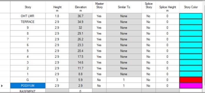
Figure 2 Story Data
IS1893:2016 SEISMICANALYSIS DESCRIPTIO N
Table 1 DESIGN CODE
1 Framing Structure
4.2 SECTION PROPERTIES
2 Section Properties
1893:2016
W0 Wind 0 INDIAN 875:2015
W90 Wind 0 INDIAN 875:2015
Live 0
Table 5 Load Pattern
5.1. SEISMIC ANALYSIS
Fortheanalysispurposeweconsidertwotypesofanalysis Static analysis and Dynamic analysis both analyses have theirownsignificance.
Mass source
Seismicweightofthestructure–itisthesumofdeadload andspecifiedamountofimposedloadsonthestructure.
D=1 & L=0.25 if imposed load less than 3kN/m2. D=1 & L=0.25,L>3=0.5ifimposedloadgreaterthan3kN/m2.
ReferIS1893:2016
SeismicZone III
Seismic Zone Factor(Z) 0.1
SiteType TypeII
Importance Factor(I) 1.2
Response Reduction Factor (R) 3
Table3(clause 6.4.2)
Table3(clause 6.4.2)
Table4(clause 6.4.2.1)
Table8(Clause 7.2.3)
Table9(clause 7.2.6)
DampingRatio 0.05 (Clause7.2.4) SoilProfile Aspersoilreport Type2
Table 6 General Design Parameter
CALCULATED BASE SHEAR Function
2718.1135
Table 7 Base Shear
5.2. WIND ANALYSIS
Computation of Wind analysis parameter is done by referringIS875Part31987
International Research Journal of Engineering and Technology (IRJET) e-ISSN: 2395-0056
Volume: 11 Issue: 05 | May 2024 www.irjet.net p-ISSN: 2395-0072
Class of the Structure General
Probable Design Life(Years) 50
Risk Co-efficient, K1
Clause 5.2
AppendixA
Table
5.5. BUCKLING ANALYSIS:
5.3. P-DELTA ANALYSIS
The P-Delta analysis is a type of Geometric nonlinearity, whichaccountsforsecondarystructuralbehaviorwhenaxial andtransverseloadsaresimultaneouslyappliedtobeamor wallelements’-Delta effectusuallybecomesprevalentina tall structure that is experiencing gravity loads and large lateral displacement due to wind or other forces. If the lateral displacement or the vertical axial loads are significant,P-Deltaanalysisshouldbeperformed.
Thisanalysisisperformedtillthetolerancelimitof0.0001 D=1.5or(D=1.2+L=1.2)whicheverisMore(IS456:Table 18).
InalltypesofanalysisP-deltaeffectisconsidered.
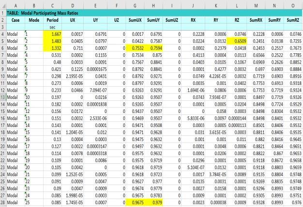
5.4. MODAL ANALYSIS
Firstthreemodesshouldcontributemorethan65%mass participation.
Thefundamentalnaturaltimeperiodofthebuildinginthe twoprincipalplandirectionsaremorethan10%difference and for principal plan directions to rotational mode 10% timeperiodismandatory
For N’th mode should contribute more than 90% mass participation. IS 1893: table-6(vii)
IS 1893 2016: clause 7.7.5.2
Whenevertheelevationaspectratioisgreaterthan4then thebuildingisgovernbybucklinganalysis
Itisglobalanalysis
Heightratio(H/W)=1.66
Inthisprojectbucklinganalysisisnotgovern
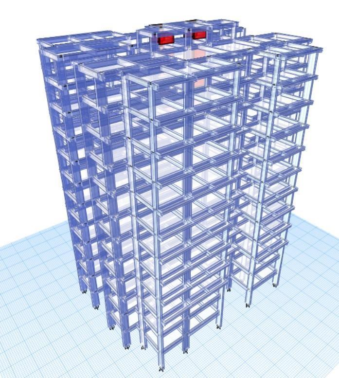
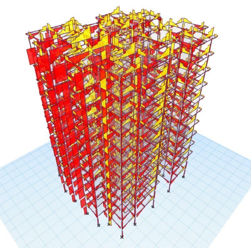
6.ANALYSIS RESULTS
Thestructureunderwentordinarymomentresistingframe analysis utilizing the joint coordinate command to define jointcoordinatesandinitiatestructuralspecifications.The member incidence command was employed to establish connectivitybetweenjoints,modelingcolumnsandbeams with beam elements. Specific member properties were designated for each member. The analysis provided maximum design loads, moments, and shear for each member,guidingthesubsequentstructuraldesignprocess.
International Research Journal of Engineering and Technology (IRJET) e-ISSN: 2395-0056
Volume: 11 Issue: 05 | May 2024 www.irjet.net p-ISSN: 2395-0072
5 SHEAR FORCE DIAGRAM (IN 2-2 DIRECTION)
Figure 6 BENDING MOMENT DIAGRAM (IN 2-2 DIRECTION)
7 AXIAL FORCE DIAGRAM
Figure 8 TORSION DIAGRAM (DEAD + LIVE)
Volume: 11 Issue: 05 | May 2024 www.irjet.net
7.1.DESIGN LOAD COMBINATIONS:
Designingstructureswouldbecomeprohibitivelyexpensive ifalltypesofforceswereappliedatalltimesformaintaining serviceability and safety. To address this, the concept of characteristicloadshasbeenembraced,ensuringthatinat least95percentofcases,theseloadsarecalculatedbasedon the average or mean load from logical combinations of all mentioned loads. Standards such as IS 456:2000, IS 875:1987 (Part-V), and IS 1893 (Part-I):2002 specify the loadcombinationstobeconsideredinstructuraldesign. SNO. DESIGNLOADCOBINATION
Theprimarygoalofstructuraldesignistoensurethatthe designedstructurecaneffectivelyfulfillitsintendedfunction and safely endure the various influences it will encounter throughoutits useful life. These influencesmainlyinclude loads and other forces exerted upon the structure. Additionally,considerationsshouldbegiventofactorslike temperature fluctuations and foundation settlements. The designmethodsemployedforreinforcedconcretestructures encompass the working stress method, ultimate load method, and limit state method. In this context, the limit statemethodhasbeenchosenforthedesignofslabs,beams, columns,andstairs.Inthelimitstatemethod,thestructure isengineeredtosafelywithstandallforeseeableloadsduring itslifespanwhilemeetingserviceabilityrequirementssuch as limiting deflection and preventing cracking. The acceptablesafetyandserviceabilitylimitsbeforefailureare termed limit states. To ensure an adequate level of safety andserviceability,allrelevantlimitstatesmustbetakeninto accountduringthedesignprocess.Thestructureshouldbe designedbasedonthemostcriticalstateandsubsequently verifiedagainstotherlimitstates.
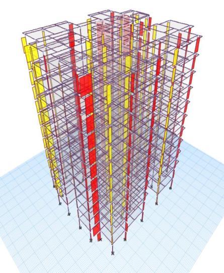
Column Rebar Percentage
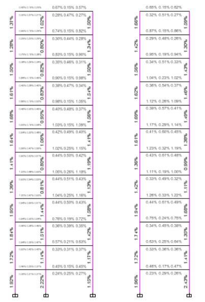
Figure 9 ELEVATION 2
Table 9 Load Combinations
International Research Journal of Engineering and Technology (IRJET) e-ISSN: 2395-0056
Volume: 11 Issue: 05 | May 2024 www.irjet.net p-ISSN: 2395-0072
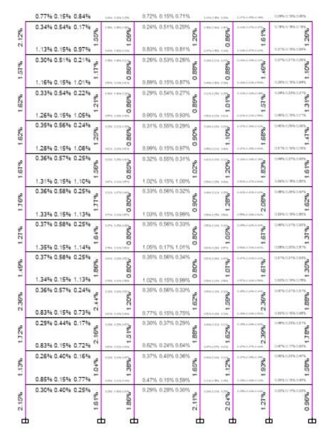
Figure 10 ELEVATION 3
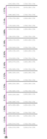
Figure 11 ELEVATION 4
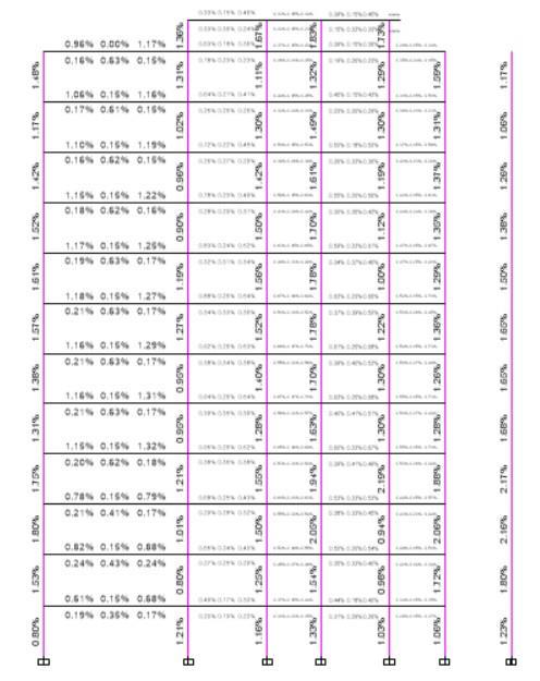
Figure 12 ELEVATION 5
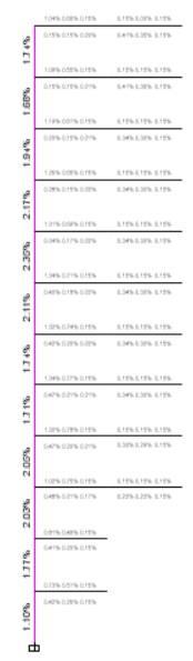
Figure 13 ELEVATION 7
International Research Journal of Engineering and Technology (IRJET) e-ISSN: 2395-0056
Volume: 11 Issue: 05 | May 2024 www.irjet.net p-ISSN: 2395-0072 © 2024, IRJET | Impact Factor value: 8.226 |
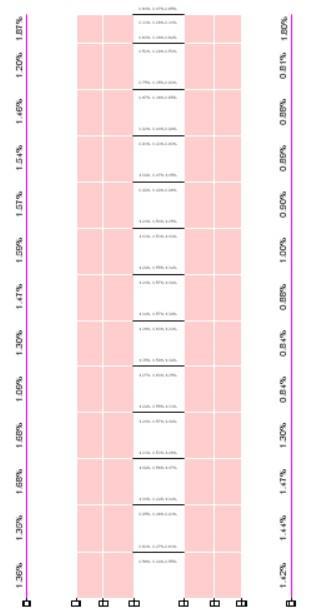
Figure 14 ELEVATION 6
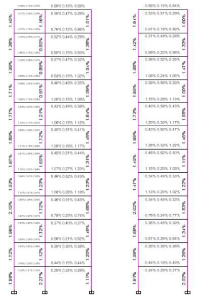
Figure 15 ELEVATION 8
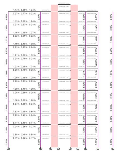
Figure 16 ELEVATION 9
9. FOUNDATION DESIGN
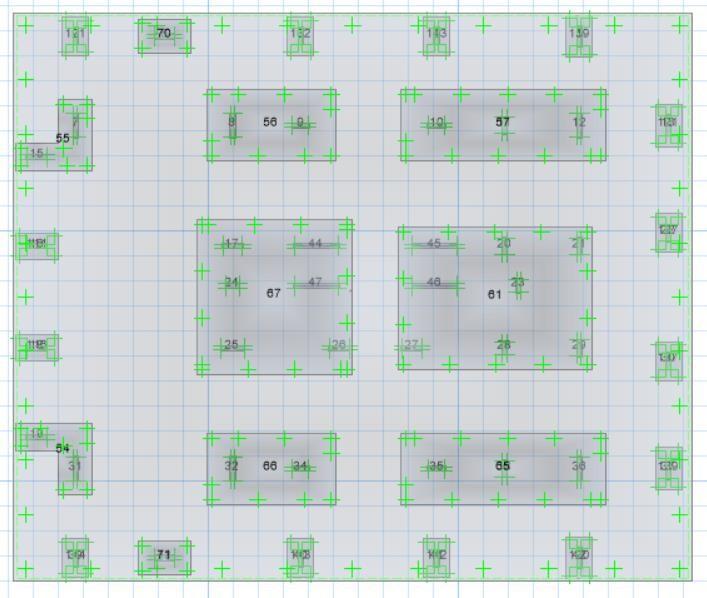
Figure 17 Mathematical Modal
International Research Journal of Engineering and Technology (IRJET) e-ISSN: 2395-0056
Volume: 11 Issue: 05 | May 2024 www.irjet.net p-ISSN: 2395-0072
Foundationisapartofastructuralsystemthatsupportsand anchors the superstructure of a building and transfers its loadsdirectlytotheearth.Inthisprojectwehaveconsidered isolatedfootingbasedongeotechnicalreport.TheSBCofthe soil is 250 KN/m2 based on geotechnical report. The allowablesettlementforisolatedfootingis50mm.Wehave usedM40concretegrade,Fe500&Fe415steelgrade
9.1. Load combinations used for analysis and design of foundation
STRENGTH LOAD COMBINATION SERVICE LOAD COMBINATION
1.5
+1.5SPECY 1D+1SPECY
1.5D+1.5W0 1D+1W0
1.5D–1.5W0 1D–1W0
1.5D+1.5W90 1D+1W90
1.5D–1.5W90 1D–1W90
1.2D+1.2L+1.2W0
+1.2L–1.2W0 1
1.2D+1.2L+1.2W90 1D+0.8L+0.8W0
1.2D+1.2L–1.2W90 1D+0.8L–0.8W0
1.2D+1.2L+1.2SPECX 1D+0.8L+0.8W90 1.2D+1.2L+1.2SPECY 1D+0.8L–0.8W90
0.9D+1.5W0
0.9D–1.5W0
0.9D+1.5W90
0.9D–1.5W90
0.9D+1.5SPECX
0.9D+1.5SPECY
Table 10 Load Combination
9.2. Material properties
Raftsize–28.95mX24.25mX0.6m. Dropsize
Table 11 Drop Size
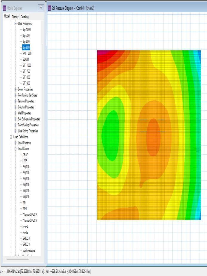
9.3. Ground Bearing pressure check (GBP)
ThegroundbearingpressureshouldbelessthanSBCgiven in geotechnical report. The SBC is 300 KN/m2 > GBP 226 KN/m2.Henceitissafe.
2024, IRJET | Impact Factor value: 8.226 | ISO 9001:2008
International Research Journal of Engineering and Technology (IRJET) e-ISSN: 2395-0056
Volume: 11 Issue: 05 | May 2024 www.irjet.net p-ISSN: 2395-0072
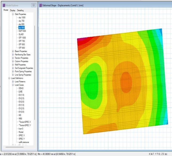
9.4. Settlement check
The maximumallowablesettlement forRaft foundation is 50mmfor(D+L)combination.
The allowable settlement (50mm) > the settlement occurring (45mm),Hencesafe.
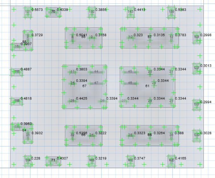
9.5.
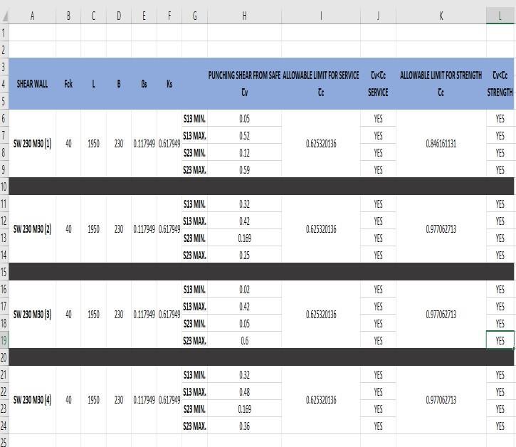
Punchingisaservicecriterionsothepunchingischeckedin serviceloadcombination.Thepunchingratioshouldbeless than1.Thepunchingratioisnotdisplayedforshearwallit shouldbemanuallychecked.Thepunchingratioislessthan 1,Hencesafe.
International Research Journal of Engineering and Technology (IRJET) e-ISSN: 2395-0056
Volume: 11 Issue: 05 | May 2024 www.irjet.net p-ISSN: 2395-0072

Punchingstressesatthedistanced/2fromtheedgeofthe columnshouldbelessthan 0.25 (β+0.5)forstrength envelope.ThestressSW1&SW2andSWCombinedfooting are<Tc,hencesafe.
Slab reinforcement design & Crack width check
DIREC TION MOM ENT (KN\m) Area of steel requir ed(AST REQ) (mm^ 2/m) Provided AST (mm^2/m ) Cra ck wid th< 20 mm
Layer-1
Dir-1 1250 8200
Raft 600
20@100 PASS Layer-1
25@100
Dir-1 750 7500 Layer-1
20@100 PASS Layer-1
25@100
Table 12 Slab Reinforcement Detail
Crack widthisperformedin non-lineartypeofanalysisin strengthloadcombination.Themoment(m11)indirection1 and the moment (m22) in direction 2 is calculated using serviceenvelope.Theareaofsteelrequired(ast)iscalculated using strength combination in both direction 1& 2. For isolated footing only bottom reinforcement is given & for combinedfootingbothtopandbottomisgiven.Maximum crackwidthallowedis0.2mm.
10. Conclusion
• ThedesignbasedonE-Tabsensurestheadequacy ofthestructureconcerningserviceability,strength, andcost-effectiveness.
• TheuseofETABSsoftwarenotonlysavestimebut alsoimprovestheprecisionofstructuraldesign.
• Structural elements underwent design using a combination of manual methods and software assistance. Urban areas, dealing with limited availableland,choosemulti-storyconstructionsto maximizetheutilizationofverticalspace.
• Instead of clearing forests and swamps for construction, vertical towers can accommodate residences, shopping centers, and factories,
contributing to the preservation of the environment.
• The design and analysis tasks performed using ETABScanalsobereplicatedinStaadProforresult comparison.
• Inadditiontodesigning,attentionmustbegivento theprovisionoffoundations andtankswithinthe projectscope.
• Dynamicanalysisisacrucialaspectthatneedstobe conducted to assess the structural response effectively.
• Diverse options for slabs, columns, various footing types, and foundation designs can be explored and applied as part of the project's flexibility and adaptability.
• Utilizing both software and manual analysis methods, providing comprehensive details on variousdepthcases,assessingthenumberoffloors needed based on the soil's safe bearing capacity, presenting a case study demonstrating plate load test execution, illustrating the subsurface strata profile in a specific research location, and conducting foundation analysis using software mechanismsfordifferenttypes.
[1]NidhishVijayPawar,NeelSanjayPatel,RajanMayaram Verma, Qureshi Mohammed Naved, (2023) “Design and AnalysisofG+22ResidentialBuildingUsingETABSjournal (IJAEM)Volume5,Issue4April2023,pp:1604-1612ISSN: 2395-5252”
[2]FathimaShalbana,NibaE,FarsanaCV,AthulyaVijayN, (2022)“AnalysisandDesignofMultistoreyBuildingusing ETABSjournal(IJERT)ISSN:2278-0181Vol.11Issue05“
[3]AnjumAsfi,VikashKumarBadal,Dr.AlokSingh,(2022) “ANALYSISANDDESIGNOFMULTISTORIEDEARTHQUAKE RESISTANTBUILDINGG+25journal(IRJET)e-ISSN:23950056Volume:09Issue:02”
[4]AyushChandrakar,ManasRathore,(2021)“257Design of Multistoried Residential Building (G+5) Using ETABS softwarejournalIJSDRVolume6Issue5ISSN:2455-2631”
[5] Abhishek Kumar Ranjan1, Aditya Pratap Singh2 , HarendraNathPandey,(2022)“AnalysisandDesignofG+21 BuildingusingETABSjournal(IJRASET)Volume10IssueIII ISSN:2321-9653
International Research Journal of Engineering and Technology (IRJET) e-ISSN: 2395-0056
Volume: 11 Issue: 05 | May 2024 www.irjet.net p-ISSN: 2395-0072
[6]ShubhamBorkar,Dr.G.D.Awchat,(2021)“ANALYSISAND DESIGNOFG+6BUILDINGINDIFFERENTSEISMICZONESBY USING SOFTWARE journal (IRJET) e-ISSN:2395-0056 Volume:06Issue:05p-ISSN:2395-0072”
[7] Mr. Piyush Kumar Tripathi, Dr. Yusuf, Mr. Arvind Vishwakarma,(2021)“AReviewonAnalysisofFoundation &its Super Structureunder the SBC Condition of Soil SBC journal(IJCET)E-ISSN2277–4106,P-ISSN2347–5161”
[8] Zia-abe Deen. S. Punekar, M H Kolhar , Anjum Algur , Kushappa M K, (2017) ANALYSIS AND DESIGN OF RAFT FONDATION JOURNAL IJRET eISSN: 2319-1163 | pISSN: 2321-7308”[9]CSIUSERGUIDE
© 2024, IRJET | Impact Factor value: 8.226 | ISO 9001:2008 Certified Journal | Page