International Research Journal of Engineering and Technology (IRJET) e-ISSN: 2395-0056
Volume: 11 Issue: 03 | Mar 2024 www.irjet.net p-ISSN: 2395-0072


International Research Journal of Engineering and Technology (IRJET) e-ISSN: 2395-0056
Volume: 11 Issue: 03 | Mar 2024 www.irjet.net p-ISSN: 2395-0072
Ahammed
1234Graduate Student, 5Assistant Professor Department of Mechanical Engineering, AWH Engineering College Calicut, Kerala, India
Abstract – Electro-pneumatic control system is an integration of pneumatics and electrical technology. The control of pneumatic components by electrical impulses is known as electro-pneumatics. Electro-pneumatic commonly used in low-cost industrial applications. Electro-Pneumatic system consist of electrical control system operating pneumatic power system. In electro-pneumatic system solenoidvalveareusedastheinterfacebetweenelectricaland pneumatic system. Control of Electro-pneumatic system is achievedusingeitheracombinationofrelayandcontactorsor PLC.In this work consist design and simulation of pneumatic cascade A+B+B-A- sequential circuit using FluidSim -P Software.
Key Words: Electro-Pneumatic Sytem, Simulation, PLC, Relay.
1.INTRODUCTION
Variousautomationtechniqueplaysakeyroleinenhancing overallindustrialproductivity.Fluidpowerhasuniquerole in industrial automation. Pneumatic based on fluid power principle.
Pneumatic is the study of system operated by air under pressure.“Pneuma”isaGreekwordwhichmeans“Breath”. Air taken from the atmosphere is compressed in a compressor, and this compressed air is used to produce necessaryworkoutput.Electro-pneumaticcircuitsareone of the industrial automation cornerstones. Programmable LogicControllers(PLC)areoneofthemaincomponentsof thesecircuits.Electro-pneumaticcircuitarecommonlyused forlow-cost industrial automations.In electro -pneumatic system pneumatic power system operated by electrical control system. Solenoid valve act as interface between electricalandpneumaticsystem.
FluidSIMisasoftwaretoolforcreatingsimulatinghydraulic, pneumatic, electro-hydraulic electro-pneumatic digital electronic system. FESTO FluidSim software is used for simulationofpneumaticpowersystem
Main aim of work is design simulate electro-pneumatic cascade sequential circuit A+B+B-A-configuration, using variouselectricalandpneumaticcomponents.
Inapneumaticsystemcompressoristheonlydevicewhich consumes electricity. In industry electro -pneumatic have wide applications. In electro-pneumatic circuit solenoidoperatedvalves,starter/pushbuttons,make/breakswitches working using electricity. Generally, in pneumatics, air movesthespoolbutinElectro-pneumaticsinsteadofusing airtomovethespoolofdirectioncontrolValveapplyvoltage toasolenoidcoil.Thisvoltagewillgenerateanelectromotive force,resultingintheshiftingofspool
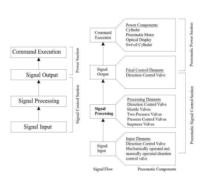
Pneumatic system generally consists pneumatic signal controlsectionandpneumaticpowersection.Mechanically operated push button is commonly used as signal input elements.Pneumaticsignalisgettingprocessedusingsignal processing unit. Signal output execute extension or retractionofcylinderorclockwiseoranticlockwisemotion ofrotoractuator.Flowcontrolelementsactasaninterface between pneumatic signal control section and pneumatic powersections.

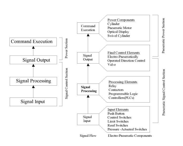
Electro-pneumaticsystemconsists Electricalsignalcontrol sectionandpneumaticpowersection.

International Research Journal of Engineering and Technology (IRJET) e-ISSN: 2395-0056
Volume: 11 Issue: 03 | Mar 2024 www.irjet.net p-ISSN: 2395-0072
Electro-pneumaticcontrolsinvolvethreeimportantsteps
Signal generation using input devices: Signalisgenerating usingdevicessuchasswitches,contactors,sensors.
Processing of signals: Signals are processed using contactors and relays, or programmable logic controllers (PLC).
Signal Output: Outputfromsignalprocessingunitsareused to activate output devices like solenoids, indicators or audiblealarms.

Inoperationofelectro-pneumaticcontrollersystem,electropneumaticcontrolsystemisnotshowninasingleoverall circuit diagram, but in two separate diagram one for electricalpartandoneforpneumaticpart.
Componentsofelectricalsignalcontrol
Sevenelectricaldevicesarecommonlyusedinthecontrol of fluidpowersystem
Manuallyactuatedpushbuttonswitches
Limitswitches
Pressureswitches
Solenoids
Relay
Timers
Temperatureswitches
Otherdevicesalsousedinelectro-pneumaticare
Proximitysensor
Electriccounter
Manually actuated push button switches: Pushbuttonis usedtoopenorcloseelectriccontrolcircuit.Theyareused toapplycurrenttoaloadorinterruptacircuit.Pushbutton isdistinguishedaccordingtocontactbehavior.
Normally open: In the case of normally open contact the circuit is open if the switch is in its initial position (not actuated)Thecircuitisclosedbypressingthepushbutton
currentflowstotheload,whentheplungerisreleased,the springreturntheswitchtoitsinitialposition,interrupting thecircuit.
Normallyclosed:Inthiscasethecircuitisclosedwhenthe switchisinitsinitialposition.Thecircuitisinterruptedby pressingthepushbutton
Change-over:Changeovercontactcombinesthefunctions of the normally open and normally closed contact in one device Changeovercontactsareusedtocloseonecircuit andopenanotherinoneswitchingoperationcircuitsare momentarilyinterruptedduringchangeover
Normallyopen NormallyClosed Change-Over
Fig3:Manuallyactuatedpushbuttonswitchessymbol
Limit switches: Limitswitchesactivatedbythepositionof a fluidpowercomponent. Theactuationoflimitswitch provides an electrical signal that causes an appropriate systemresponse.
Limitswitchesareclassifiedbymethodofactuationlever actuatedandspringactuated. 1
Fig4:Limitswitchsymbol
Pressure switches: Pressureswitchesarebasicallyelectropneumatic signal converter, and opens or closes an electrical switch when a pre-determined pressure is reached. Bellows or diaphragm are used to sense the changeofpressureandexpandorcontractinresponse.
Fig5:Pressureswitchsymbol
Solenoids: Electrically actuated direction control valves form the interface between the two parts of an electropneumaticcontrol.Mainobjectiveofelectricallyactuated DCVs include controlling air supply and extending and retractingcylinderdrives.TheDCVsarecontrolledwiththe aid of solenoids can be divided in to two group spring returnvalvewhichremainactuatedaslongascurrentflow through the solenoid. Double solenoid valves which maintainthelastswitchedpositionevenwhennocurrent flowsthroughthesolenoid.

International
Volume: 11 Issue: 03 | Mar 2024 www.irjet.net p-ISSN: 2395-0072
zero.Foreachelectricalpulseinputtothecoil,thecounter value incremented by one. Down counter counts down electricalsignalsfrompresetvalue.
Fig6:5/2-waydoublesolenoidvalve
Relay: A relay is an electromagnetically actuated switch. Whenvoltageisappliedtosolenoidcoil,anelectromagnet fieldresult.Thiscausesthearmaturetoattractedtothecoil core. The armature actuates the relay contacts either openingorclosingthem,dependingonthedesign.Areturn spring restore the armature to its initial position when currenttothecoilisinterrupted.
Fig10:RelayCounter
Identification of components
Thecomponentsinthecircuitdiagramofacontrolsystem areidentifiedbyaletterinaccordancewithfollowingtable. Componentswithidenticalidentifyinglettersareassigned consecutivenumbers.
7:Relay
Time delay relays: Timersarerequiredincontrolsystemto introduce time delays between work operations via the associated control elements. Electronic timers are most commonlyused.Therearetwotypesoftimedelayon-delay timerandoff-delaytimer.
Fig8:Timedelayrelay
Temperature Switch: Temperature switch automatically senses a change in temperature and open or closes an electrical switch when a predetermined temperature is reached.Itcanbeeithernormallyopenorclosed.
Proximity sensors: Commonly using proximity sensor in pneumaticcircuitasshownbelow.
Fig9:ProximitySensor
Electronic Counters: Electroniccountersareusedtocount thenoofsignalspassingthroughit.Therearetwotypesof countersupcountercountselectricalsignalsupwardsfrom
Table1:IdentificationLetterofComponents
3.WORKDONE
Inanelectro-pneumaticsequencecircuitusuallyhavetwoor more cylinder that extend or retract in pre-defined sequence.Inordertoavoidsignalconflictcascademethodis used.
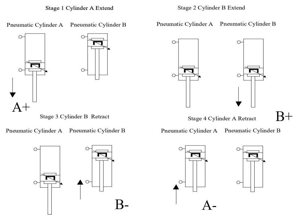
RequiredSequencemotionA+B+B-A-

Fig11:PositionalLayoutwithNotation

International Research Journal of Engineering and Technology (IRJET) e-ISSN: 2395-0056
Volume: 11 Issue: 03 | Mar 2024 www.irjet.net p-ISSN: 2395-0072
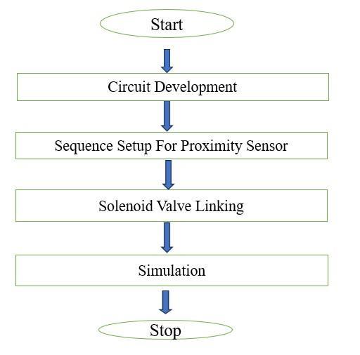
FlowChartforElectro-PneumaticCircuitDesign

12:FlowChart-Electro-PneumaticCircuitDesign
AsequentialcircuitisdesignedwithA+B+B-A-motion.Total twodoubleactingcylindersareused.Eachonerespectively designed and dedicated to the sequential operation in system.Eachcylinderactivateswithtwospecificproximity sensorsforthemotionfunction.
Fluid Sim Pneumatic simulation software is used for simulating pneumatic circuit. Fluid Sim Pneumatics is a teaching tool for simulating pneumatics basics and runs using Microsoft Windows. The Fluid Sim Pneumatic Simulation software supports learning, educating, and visualizing pneumatic knowledge. The Pneumatic componentswhichareexplainedwithtextualdescriptions, figures,animationsanditsworkingprinciples.Theuserwill quicklylearntodrawandsimulate electro-pneumaticcircuitdiagram.
Case 1:Theelectro-pneumaticdiagramgivenbelowshowsa simple A+A- circuit. As the piston is in A0 it is in on condition.WheneverA0sensoronelectriccurrentflowfrom 24Vto 0V, then left position of valve KA+ will get active compressedairwillgotoleftsideofpneumaticcylinderand pistonwillmoveforward.Whenpistoncompletelyoutward A1 close KA- get electricity right side will become active compressed air go to right side of cylinder piston moves backwarddirection.

International Research Journal of Engineering and Technology (IRJET) e-ISSN: 2395-0056
Volume: 11 Issue: 03 | Mar 2024 www.irjet.net p-ISSN: 2395-0072
. Fig16:DuringRetraction
Theabovecircuitpistonwillmoveforwardandbackward continuouslywiththehelpofsensors.
Case 2: whenpushbuttonpressedcylindermovesinforward directionandreleasingpushbuttonshouldmovebackward direction.
Case 3: Push button can be replaced by switchpiston will move forward and stay there, when the switch is again pressed the cylinderretracted.

International Research Journal of Engineering and Technology (IRJET) e-ISSN: 2395-0056
Volume: 11 Issue: 03 | Mar 2024 www.irjet.net p-ISSN: 2395-0072
Case 4: Whenpressingswitchthepistonshouldmoveforwardand backwardautomaticallyuntilagainpressingswitch.
AssoonasswitchispushedrelaygotelectricityR0isclosed A0functionallyinitiallyclosedduetopistonisinretracted conditionKA+getelectricityleftsideofsolenoidvalvewill active.Socompressedairgotoleftsidecylinder,pistonhas start moving forward. As soon as piston moves a little bit forwardA0openKA+deactivated.Assoonaspistonreach A1 the circuit closed, KA- got electricity the right side of solenoidvalveactivatedcompressedairgoestorightsideof valvepistonretracted.Thiswillberetractedconditionuntil theswitchisagainpressed.
Case 5: Latchingcircuitmainlyconsistnormallyopenpush button,normallyclosedpushbutton,relaycoilandrelayNo switch.
Fig26:A+A-LatchingCircuit
Assoonasstartbuttonispushedelectricityflowingthrough start push button, electricity flowing through stop push button.Startbuttonisfunctionallyclosedandstopbuttonis normallyclosed.
As soon as electricity go through R0, R0 normally open switchwillclose.AssoonasR0closedelectricitygothrough startbuttonandelectricitygothroughR0.Evenafterpush buttondisengageselectricityisgoingthroughR0andreach relaynowsystemwill work automaticallytillpushbutton

International Research Journal of Engineering and Technology (IRJET) e-ISSN: 2395-0056
Volume: 11 Issue: 03 | Mar 2024 www.irjet.net p-ISSN: 2395-0072
pressed. When stop button pressed, R0 deactivated functionally closed of R0 converted in to normally open. Evenifstopbuttoncomebackthecircuitnotwork.
Fig27:A+A-LatchingCircuit:Extension
Fig28:A+A-LatchingCircuit:Retraction
Electro Pneumatic Circuit Diagram for The Proposed Design A+B+B-A-
Step 1:DrawthecylinderAandBwith5/2doublesolenoid directionalcontrolvalve.Connectcompressedpowersupply. Indicatethepositionofthelimitswitch.
Fig29:CylinderwithSolenoidValve figurebelowrepresentelectricalcircuitdiagramfor proposeddesign.
Fig30:ElectricalCircuitDiagram
Table 2 indicate a list of symbols that explains the cycle movement
Symbol
Detail
KA+ SolenoidforforwardmotionofcylinderA
KA- SolenoidforbackwardmotionofcylinderA
KB+ SolenoidforforwardmotionofcylinderB
KB- SolenoidforbackwardmotionofcylinderB
R1 Relayforgroupone
R2 Relayforgrouptwo
A0
A1
SensorindicatesCylinderAcompletely retractedposition.
SensorindicatesCylinderAcompletely extendedposition.
B0 SensorindicatesCylinderBcompletely retractedposition.
B1 SensorindicatesCylinderBcompletely retractedposition.
SRT Startpushbutton
STP Stoppushbutton
Table2:SymbolusedandTheirDetails
Electro-pneumaticcircuitconsisttwo-partpneumaticpart and electro part. Pneumatic part of circuit consists two doubleactingcylinder,two5/2doublesolenoidvalveand sourceofcompressedair.Electropneumaticcascadecircuit consist two group R1 and R2 are relay assigned to each group.RelayR1usedforA+B+movementandRelayR2used forA-B- movement.Grouponeisactive whenrelayone is activeandgrouptwoisactiverelaytwoisactive. Thereare foursensorsareusedA0,A1,B0,B1.A0tellsincylinderA piston completely in retracted position, A1tells piston completelyinextendedposition.B0tellsincylinderBpiston completelyinretractedposition,B1tellspistoncompletelyin extended position. For A+ motion R1 should be active B0 sensorshouldsense.WhenKA+getactivatedA+motionget activated. For B+ motion R1, A1should be active. KB+ get

International Research Journal of Engineering and Technology (IRJET) e-ISSN: 2395-0056
Volume: 11 Issue: 03 | Mar 2024 www.irjet.net p-ISSN: 2395-0072
activatedB+motionhappens.ForB-totakeplaceR2should be active B1 sensor should be sensed. For A- motion R2 shouldbeactiveandB0sensorshouldbesensed.
Step 2:A+Movement
Step 4:B-Movement
Fig33:B-Movement
Step 4:A-Movement
Fig31:A+Movement
Step 3:B+Movement
Fig34:A-Movement
In the above circuit after A- motion completed the circuit stopped.Forcontinuousmotionanotherswitch(Normally open contactA0)Placedasshownbelow.
Fig32:B+Movement

International Research Journal of Engineering and Technology (IRJET) e-ISSN: 2395-0056
Volume: 11 Issue: 03 | Mar 2024 www.irjet.net p-ISSN: 2395-0072
Designing Sequential Electro-Pneumatic System Using PLC Ladder Diagram
The PLC controls industrial machines and processes. In differentareasoftheindustry,PLCarebeingapplied.Inthe pastthemovementsofindustrialmachineswerecontrolled by relay circuits. These relay-controlled systems were replaced by PLC. The primary function of the PLC was to perform the sequential operations that were previously implementedwithrelays.
Ladder logic is a programming language that represents aprogram byagraphical diagram based onthe circuitdiagramsof relaylogichardware. Ladderdiagrams are used to describe the logic of electrical control system. Ladderdiagramsarespecializedschematicscommonlyused todocumentindustrialcontrollogicsystem.Theyarecalled “ladder”diagramsbecausetheyresemblealadder,withtwo vertical rails (supply power) and as many “rungs” (horizontallines)astherearecontrolcircuitstorepresent.

International Research Journal of Engineering and Technology (IRJET) e-ISSN: 2395-0056
Step 3: B-Movement
Fig39:B-Movement
Step 4: A-Movement
Fig40:A-Movement
4.CONCLUSION
Nowadaysautomationisemployedineverysmallandlarge industry. Automated process has reduced human effort savedtimeandincreasedrateofprocesscompletion.Work in this article consists design and simulation of electropneumatic sequential circuit using Fluid Sim -Pneumatic software. Electric circuit are designed and sequence of operationaretestedbyusingFluidSim-PneumaticSoftware. Electrical ladder diagram easily converted in to a PLC programmingladderdiagramforabovesequential motion andsimulatedusingFluidSim-Pneumaticsoftware.
[1] Yudhveer Kumar Verma and Namrata Tripathi “Analytical approach for hot packing machine on electro-pneumaticcircuitwithon-delaytimer” Journal of Mathematical Problems, Equations and Statistics 2021;2(1):66-74.
[2] VyasrajKoppar,RavindraMLatheandPatilSiddharam “AutomationofaPlanerUsingElectropneumaticDevices and Programmable Logic Controller” International Journal of Engineering Research and Development Volume7,Issue11(July2013)
[3] Adam Szcześniak, and Zbigniew Szcześniak “Fast Designing Ladder Diagram of Programmable Logic Controller for a Technological Process” Intl Journal of ElectronicsandTelecommunications,2022,Vol.68,No. 4,Pp.709-714
[4] Purva Rakhade “PLCBased Pneumatic Pick and Place System” International Research Journal of ModernizationinEngineeringTechnologyandScience Volume:02/Issue:05/May-2020
[5]Mr. YadhunandanD, Mr. VinodKumar HP “Designand Development of PLC Controlled Pneumatic Pressing System”InternationalJournalofEngineeringResearch& Technology(IJERT)ISSN:2278-0181Vol.12Issue12, December-2023
[6] Avunoori Anudeep Kumar, Murahari Sunil Kumar “SimulationforAutomationofManufacturing,Fillingand Capping the Bottles” International Journal of Modern EngineeringResearch(IJMER) Vol.7,Iss.2,Feb.2017,62 ISSN:2249–6645
[7] ShaliniPukkella,Dr.V.SureshBabu,Dr.K.M.Abubacker “DesignandDevelopmentofPickandPlaceArmRobot” International Research Journal of Engineering and Technology(IRJET)Volume:07Issue:08 Aug2020.
[8] VyasrajKoppar,RavindraMLatheandPatilSiddharam “AutomationofaPlanerUsingElectropneumaticDevices and Programmable Logic Controller” International Journal of Engineering Research and Development Volume7,Issue11July2013
[9] Rahul B. Pandhare1, Rajesh M. Metkar “Design, Development and Automation of Hydraulic Broaching Machine”InternationalJournalofInnovativeResearchin Science,EngineeringandTechnology.Vol.6,Issue7,July 2017
[10] PulkitBaralaPP,GauravTiwariPPR,RDineshKumarP “AutomationofProcessStationUsingElectro-Pneumatics” IJISET - International Journal of Innovative Science,
Volume: 11 Issue: 03 | Mar 2024 www.irjet.net p-ISSN: 2395-0072 © 2023, IRJET | Impact Factor value: 8.226 | ISO 9001:2008

International Research Journal of Engineering and Technology (IRJET) e-ISSN: 2395-0056
Volume: 11 Issue: 03 | Mar 2024 www.irjet.net p-ISSN: 2395-0072
Engineering & Technology, Vol. 1 Issue 9, November 2014.
[11] Vijaylaxmi G.Biradar, Siddharam Patil, R M Lathe “Automation of Sheet Bending Machine Using Electro PneumaticDevices”InternationalJournalofScientific& EngineeringResearchVolume3,Issue9,September-2012 1.ISSN2229-5518.
[12] Pawan Koppa, Dr.N. Nagaraja, Amith.V, Sushilendra Mutalikdesai,Vyasaraj.T,GururajHattiPramodKumar, RohitKumarPandey,S.Vishwanath “Developmentand Fabrication of Electro Pneumatic Automatic Stamping Machine”InternationalJournalofInnovativeResearchin Science, Engineering and Technology Vol. 5, Issue 9, September2016
[13] Jagadeesh T “Pneumatics: Concepts, Design and Applications”UniversitiesPress(India)PrivateLimited ISBN:9788173719417.
BIOGRAPHIES


Mr. Ahammed Adil P Final YearB-tech student in the Mechanical Engineering DepartmentatAWHEngineeringCollege CalicutKeralaIndia.

Mr.Jibi.R CurrentlyworkingasanAssistant Professor in the mechanical engineering department at AWH Engineering College Calicut Kerala India. He has published 13 International journals and presented two articlesininternationalconference.Hehas morethan11yearsexperienceinteaching andone-yearIndustrialexperienceinPress toolandMoldmaking.Hisinterestedareais computer aided design and analysis, Production Technology and Industrial hydraulicsandpneumatics
Mr Muhammed Ishack V FinalYearBtech student in the Mechanical Engineering Department at AWH EngineeringCollegeCalicutKeralaIndia
Mr. Rohith VT FinalYearB-techstudent in the Mechanical Engineering DepartmentatAWHEngineeringCollege CalicutKeralaIndia
Mr. Amal P K FinalYearB-techstudentin the Mechanical Engineering Department at AWH Engineering College Calicut KeralaIndia
2023, IRJET | Impact Factor value: 8.226 | ISO 9001:2008