
Mitigation of Voltage Dip and Swell Faults in Wind Energy Conversion Systems
Magda hamdy1, Dina Mourad2, Tamer A.A.Ismail31 Faculty of Technology and Education, Helwan University, Egypt, 2 Faculty of Technology and Education, Helwan University, Cairo, EGYPT, 3 faculty of technology at El Sahafa. Ministry of higher education, Cairo, EGYPT, ***

Abstract - Wind Energy Conversion Systems (WECS) are gaining popularity due to its low-maintenance functioning. WECS must stay up for at least a brief amount of time to provide dependability and stability even in the case of a network outage, according to network standards. In the literature, many strategies for implementing low-voltage riding (LVRT) have been presented. This paper examines different LVRT implementation strategies for synchronous computer-based, networked WECS across a fully assessed cascade system. converts. The inverter is operated from the machine side by employing a field-oriented control approach to drive the generator at the appropriate speed in order to harvest the greatest power from the wind turbine. To accomplishdistinctmanagementofactiveandreactivepower, the mains transformer employs a voltage-oriented control algorithm. The LVRT capabilities of the system
Key Words: wind turbines1, Voltage swells2, Voltage dips3.
1. INTRODUCTION
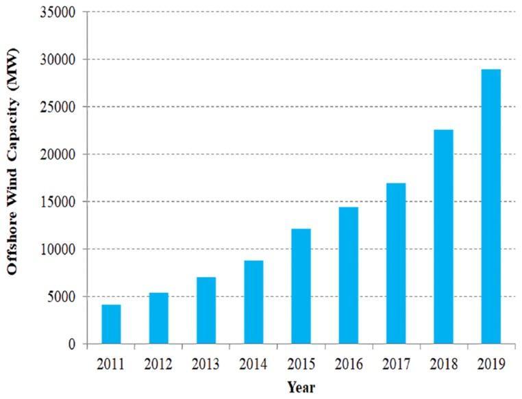
Astheworldcontinuestorapidlydevelopanddemandmore energy, the negative environmental impacts of traditional fossil fuels as well as their limited reserves have become increasingly evident. To combat this, renewable energy sources like wind energy have gained significant global attention.Wind energy is pollution-free and widely distributed,makingitanimportantrenewableenergysource inthetransitiontoalow-carbonfuture.In2020,93GWof newwindpowerinstallationswerebuilt,bringingthetotal installedcapacityto743GWworldwide.Chinacurrentlyhas the largest proportion of global wind energy capacity at 38.5%,followedbytheUnitedStatesat16.1%[1].inlightof the need to combat climate change and reduce carbon dioxide emissions, renewable energy is becoming increasinglyattractive.Windenergy,inparticular,hasmany environmental ,economic, and social advantages. Policymakers, researchers, and stakeholders should take noteofitspotentialcontributiontothetransitiontoalowcarbonfutureLookingforward[2],windpowerisprojected to continue growing rapidly, and could even become the primarysourceofglobalenergyby2050.Achievingthisgoal
willrequiresignificantrestructuringofregionalandglobal energysystems,aswellasstrategicinitiativestoovercome remainingobstacles.Ultimately,generatingaffordableand sustainableelectricitywillbecriticaltothesuccessofthis transformation[3].
ThegeneratorinaconstantspeedWPPiselectricallylocked tothe grid towhichitsstatorislinked.Regardlessmatter howquicklythewindblows,thegeneratorwillalwaysrunat thesamepace.Theconstantspeedoftherotorisdetermined by the grid frequency, the number of pole pairs in the generator,andthegearratio.Inthisconfiguration,therotor does not revolve faster than the synchronous speed. Constant speed wind turbines (CSWT) are normally stall controlled and employ induction generators to generate power.Thethree-phaserotorwindingsofthegeneratorare directly linked to the grid, while the stator windings give excitationtothegenerator.Thesynchronousspeed
1.2 WPP Variable Speed
Variable speed WPP allows the generator to be run at changing speeds in accordance with the wind. A power electronicconverter(PEC)isusedinthissystemtoconvert thegenerator'salternatingcurrentoutputtodirectcurrent andviceversa eventuallymakingitgrid-friendlyAC.Stall, pitch,andactive-stallregulationarealloptionsforvariablespeed wind turbines (VSWT). In stall-regulated WPP, the windturbine(WT)bladesaresecurelyfastenedtothehubat acertainangle,butinpitch-regulatedWPP,theblade'sangle ofattackischangedtominimisetorque.Thisisaccomplished byshiftingthedirection,orpitch,oftheblade,changingits aerodynamicefficiency.InactiveWPP,however,therotation of
2. Wind Energy System:
The use of Wind Energy Conversion Systems (WECS) has become increasingly important as a clean and sustainable source of electricity, free from the issues associated with fossilfuels[5].TheprimarycomponentofWECSisthewind turbine (WT), which converts the kinetic energy from the wind to mechanical energy that can power electrical generators. WTs can be configured as either horizontal (HAWT)orvertical(VAWT)axissystem[6].
2.1. Horizontal Axis Wind Turbine
HAWT,whichhasitselectricalgeneratorlocatedatthetopof thetower,producesmaximumenergythankstoitstalltower base. The turbine blades' variable blade pitch allows for maximumenergyproduction.AlthoughHAWT'sefficiencyis relativelyhigh,towerconstructioncostsarehigher,andthe tower's height can interfere with radar installations. Additionalcontrolmechanismsarerequiredtocontrolthe directionoftheturbineblades.[7].
2.2. Vertical Axis Wind Turbine
VAWTs rotate around a vertically arranged shaft, offering theadvantageofnotrequiringanadditionalcontrollerasthe wind is always perpendicular to the blades. Their maintenance process is easier than HAWTs and they producelessnoiseduetotheirlowerspeed.VAWTscanbe placed in various locations such as highways and roofs. However, they are less efficient than HAWTs due to their shortertowers,resultinginslowerrotationandlowerpower output.[8].
3. WECS Topologies and Generator
Different Wind Energy Conversion Systems (WECS) are established for various power rates, ranging from a few hundred kilowatts to several megawatts. This leads to various WECS designs based on different criteria, such as fixedorvariablespeedwindturbines,smallorlargewind
turbines, and grid-connected wind turbines. While synchronous generators have been traditionally used for power generation, induction generators (IGs) are increasingly being used due to their cost-effectiveness, brushless and rugged construction, and self-protection against short-circuited faults. Additionally, IGs have adequatedynamicresponseandcanproduceelectricpower at different speeds, enabling their use in isolated areas where network expansion is not feasible. When used in conjunction with synchronous generators, IGs meet the growingdemandforlocalpower[9],[10].
3.1. Induction Generator.
heuseofinductionmachineshasbecomemorepopulardue to recent advances in power electronics. Induction generators (IGs)are commonly used in fixed speed wind turbines but require a capacitor bank to supply reactive power.Foroff-gridapplicationswithconstantloads,asingle capacitor can be used for self-excitation. To control IGsin variablespeedwindturbines,back-to-backPWMinverters are used. The inverter on the IG side controls machine torque and the inverter on the grid side controls reactive power at the coupling point. Thyristor controlled reactor staticvolt-amperereactivecompensatorscanalsobeusedto controlvoltageinvariablespeedwindturbines.[11].
3.2. Slip Ring Induction Generator.
DFIG,whichisanadvancedversionofSRIG,reliesondirect coupling of stator with the system via a slip ring and converterfeeding.Recentfocushasbeenonsub-andsupersynchronous cascade drives using cycloconverters on the rotor side. Full AC-DC-AC is the current alternative which offersaround±33%workingspeedrange.Theratedpower of the converter should be around 30% of the rated generator for ±30% speed variation from synchronous speed[12].DFIGisapotentialrivalofwindenergygenerator system and eliminates the need for reactive power compensation by using the grid side converter and DC capacitorasastaticcompensator.[12].
3.3. Synchronous Generator.
The power generation industry uses large SGs for their variablereactivepowerproduction,whichhelpstocontrol voltage. The SG of a wind turbine is connected to the grid through back-to-back PWM voltage source inverters. The gridsideinvertermanagesthetransferofrealandreactive power to the grid, while the generator side converter regulates the electromagnetic torque. Using multiple SGs withalargediametersynchronousgeneratorringeliminates the need for a gearbox, which reduces weight and avoids proximityissueswiththerotorwinding.[13].
4-Types of power quality problems
4.1.Under voltage
Under voltage could occur due to high voltage drop, low distribution voltage and/or heavy loads. The premature. failureandoverheatingofmotorsarethesymptomsofunder voltage.Thevalueofundervoltageislessthanor equalto 90% of nominal value with a duration of more than one minute.
4.2.Overvoltage
Overvoltagecanbecausedfromhighdistributionvoltageor lightloads.Symptomsincludeprematurefailureofelectronic andprintedcircuitboards.Thevalueofovervoltageisequal toorabove110% ofthenominalvalueandhasdurationof morethanoneminute.
4.3.Voltage sag
Voltage sag results from weather and utility equipment problems. Problem of voltage sag for industry is the malfunction of devices which may result in huge financial losses.Voltagesagisaverydeepvoltagedropwithashort durationfrom0.5cyclesto60seconds.
4.4.Voltage swell
Voltageswelliscausedbyenergizingacapacitorbankora suddenshutdownofaverylargeload.Voltageswellisavery highvoltagerisewithaveryshortdurationfrom0.5cycles to60seconds
4.5. Harmonics
Harmonics are caused by arcs, saturated transformers ,rectifiers, motor drives and electronic loads. Symptoms includeoverheatingormalfunctionofdevices.Accordingto IEEEstandardIEEE519-2014[14],theTHDlimitsis5%for1 kVthrough69kVsystems
4.6.Voltage flicker
Flickerisdefinedas“Animpressionofunsteadinessofvisual sensationinducedbyalightstimulus,whoseluminanceor spectraldistributionfluctuateswithtime”Voltageflickeris caused by electric arc furnaces,ovens, any large-draw varyingloadandwindturbinegenerators.Generally,itcases annoyingchangesinlightinglevel.rectifiers,motordrives and electronic loads. Symptoms include over heating or malfunction of devices According to IEEE standard IEEE 519-2014[14] TheTHDlimitsis5%for1kVthrough69kV systems.
The effect of wind energy on the quality of electrical power:
Increasingtheintegrationofwindenergyintothegridcan impactthepowersystem'squalityduetothevariationsin windpowergeneration,whichposeschallengesforpower systemplannersandoperators.Thesechallengesincludethe security,stability,andqualityofwindpower.[2]Toaddress these issues, various strategies have been proposed to improvegridintegrity,allowing for flexible powersystem operationandsmoothwindpowerintegration[3].theTHD limitsis5%for1kVthrough69kVsystems.
5-Fluctuations in voltage in wind power plants connected to the grid
Voltage variations in grid-connected wind power plants (WPPs)canoccurintheformofvoltagesag,voltageswell, transient,flicker,orharmonicdistortion.Voltagesagrefers toasuddenreductioningridpotential,whilevoltageswell referstoarapidincreaseinthenominalvalueofACvoltage. Thesevariationscanlastformicrosecondstoafewminutes.
In a grid-connected WPP, the voltage variations are influencedbytheimpedanceofthetransmissionline,cable, andtransformerinthefeedinggrid.Kirchhoff'sVoltageLaw canbeappliedtoanalyzethevoltageatdifferentpointsin thesystem.WhentheWTgeneratespowertomeettheload demand, no current is drawn from the grid, resulting in equalvoltagesatthegridsideandtheWPPconnectionpoint. However, if the WT generates more or less power than demanded,thegridsidevoltagewillbelessorgreaterthan thevoltageattheconnectionpoint,respectively.
5.1.voltage sag
Alsoknownasavoltagedip,referstoasuddendecreasein theelectricalpotentialofthegrid,usuallybetween10%and 90% of its normal value, followed by a quick return to normal.Thistypicallylastsforadurationof10milliseconds to 60 seconds. Voltage sags can occur when large wind turbines are started up simultaneously, causing a high currentdrawforabriefperiod.Similarly,voltagedipscan occurduringthestartupoflargemotorsorduetogridshort circuit, which is noticeable when lights flicker on and off momentarily. The decrease in nominal voltage, known as voltagedip,atthepointofinterconnection(POI)ofthewind turbinecanbecalculatedusingthevoltagechangefactor,Ku, theratedpowerofthewindturbine,Sn,andtheshortcircuit apparent power of the grid, Sk. The acceptable limit for voltage dip is usually ≤ 3%.Voltage dips can result in the disconnectionofsensitiveloadsandequipmentfailure.To mitigate the impact of voltage dips, proper arrangements mustbemadeforthestartupofwindturbines.Alternatively, thecurrentandaccelerationoftheturbinescanbereduced byadjustingtheaerodynamicbladepitch.
5.2. Voltage swell
VoltageswellisasuddenincreaseintheACvoltagethatlasts forlessthanoneminute.Ittypicallylastsbetween30to60 seconds and has a threshold limit of 1.1 to 1.8 p.u. The minimumdurationforavoltageswellis10ms.Voltageswell canoccuringridconnectedwindpowerplantsduetoinrush currents or when large capacity wind turbines are shut down. Other causes include grid lightning strikes, earth faultsonanotherphase,andincorrectsubstationsettings. Thevoltageswellatthewindpointofinterconnection(POI) isdeterminedbytheturbine'smaximumapparentpower, gridresistanceandreactance,andnominalphasetoneutral voltage.Thelimitingvalueforvoltageriseislessthan2%. Voltageswellcancauseequipmentdisconnection,insulation aging, and harm to inadequately designed equipment. Measures to prevent voltage swell include using a soft startertoreduceinrushcurrentduringstart-upandusing transformers with tap changers. Large loads can also be connected at the point of common coupling to mitigate voltageswell.
6-LVRT METHODS
Wheneveraline-sidevoltagesagoccurs,theDCbusvoltage rises beginstoriseduetothepowerimbalancethatexists between the mgenerated and transmitted power. To give himrelief fourtechniquesareproposedhere.This LVRT techniques are applicable to all WECS with full power converterssuchasPMSGWindorSyRM energysystems. Powersupplyfrom MSCto DCAssociationcanberestricted usingoneof fourtechniques: MSCmodulationindex
-ModulationIndexControloftheMSC.
-Unloadingviamachine-sidecontrol.
-crowbarprotection.
6.1. MSC modulation index control.
This triple method uses the multiplier MSC modulation signals Va, Vb and Vc before generating sinusoidal PWM signals until the intermediate circuit voltage reaches its maximumvalueagain.ButwhentheDCbusvoltageexceeds thelimit,themultiplierdropstolowervaluesandgoes to zeroquickly,reducingthetransformeroutputtozero.The transformer closes and prevents the generator terminals fromflowingintotheDCbus,effectivelylimitingtheDCbus voltage. The main drawback of this scheme is the high transient current in the generator during the generating stationsacrossthecircuit


6.2. Unloading via machine-side control
Thevariable"MF"(whichdependsonthedirectcurrent)is multiplied by the generator's algorithm speed. "MF" decreases rapidly to zero when the voltage in the direct currentcircuit exceedsthemaximumlimit.ThePIcontrol loopdeterminesthemachine'storque.Therefore,ifthevalue of"MF"dropstozero,thetorquesignalisadjustedtozero, reducingthemotor'storquetozeroandthusgeneratingzero performancevalueforthemachine.Thisway,thegenerator current remains locked in the circuit with fewer disturbances associated with low voltage conditions and balancing the control model. When the electrical torque decreasestozero,theincreaseingeneratorspeedbecomes moreevident.
6.3.crowbar
Thegeneratorspeedincreaseishigher.
This is the traditional method used in most wind power conversionsystems(WECS).Itinvolvestheuseofachopper circuitandaresistorconnectedtoaDCcouplercapacitor. Undernormalcircumstances,thechoppercircuitdoesnot receiveagatepulse.However,ifthenetworkencountersa low voltage, the DC bus voltage rises above a certain thresholdandactivatesthecontrollerPIandthisgeneratesa non-zerosignal,allowinggatepulsestobegeneratedforthe choppercircuit.ThismethodensuresthattheDCbusvoltage remainswithinsafelimitsbydissipatingexcesspowerinthe leverbarresistance.Onedisadvantageofthismethodisthat
itrequiresaresistanceofthesameratingasthegenerator, wastingallthepowergenerated.
[4] Tawfiq,KotbB.,etal."Windenergyconversionsystem topologiesandconverters:Comparativereview."Energy Procedia162(2019):38-47
[5] Zemamou, M., M. Aggour, and A. Toumi. "Review of savoniuswindturbinedesignandperformance."Energy Procedia141(2017):383-388.
[6] Basem Tawfiq Albassioni, Kotb, et al. "Application of matrix converter connected to wind energy system." 2016 Eighteenth International Middle East Power SystemsConference(MEPCON).2017.
[7] Chen,Liu,JianChen,andZhouzhouZhang."Reviewof theSavoniusrotor'sbladeprofileanditsperformance." Journal of Renewable and Sustainable Energy 10.1 (2018).
CONCLUSION
The paper explores the effect of voltage drop and voltage amplificationonthepowerqualityoftheconnectednetwork.

Resultsrevealthatvoltagedropscanleadtosensitiveload shedding,failureofsystemfunctions,systemcrashes,data loss, and complete system shutdown. By contrast, voltage swells can lead to equipment disconnects, disrupted downtime,damagetoequipment,orreducedlifespan.Dueto theuniquebehaviorofwindpowerplants(WPPs)compared to conventional sources, careful planning is necessary to ensureWPPsareintegratedintothegrid.NetworkedWPPs, are expected to meet certain network code requirements, suchasfaultriding(FRT)orlowvoltageridingacrosspower (LVRT), power quality control, frequency control, voltage control,activeandreactivecontrolofpoweratthepointof interconnection with the network . WPPs with LVRT capability can withstand electrical disturbances on transmissionlinesandremainconnectedtothegridnetwork despitesuchdisturbances.
REFERENCES
[1] Lowe,R.J.,andP.Drummond."Solar,windandlogistic substitutioninglobal energysupplyto2050–Barriers and implications." Renewable and Sustainable Energy Reviews153(2022):111720
[2] Ali,MuhammadArifSharafat,KhawajaKhalidMehmood, and Chul-Hwan Kim. "Power system stability improvementthroughthecoordinationofTCPS-based damping controller and power system stabilizer." AdvancesinElectricalandComputerEngineering17.4 (2017):27-36.
[3] Chawda,GajendraSingh,etal."Comprehensivereview on detection and classification of power quality disturbances in utility grid with renewable energy penetration."IEEEAccess8(2020):146807-146830.
[8] Tawfiq,KotbB.,etal."Windenergyconversionsystem topologiesandconverters:Comparativereview."Energy Procedia162(2019):38-47.
[9] Al-Deen, Kareem A. Nour, and Hussain A. Hussain. "Review of dc offshore wind farm topologies." 2021 IEEE Energy Conversion Congress and Exposition (ECCE).IEEE,2021.
[10] Rahman, S., et al. "Transmission Mode for Onshore IntegrationofOffshoreWindFarms:HVDCorHVAC A Comparison Review. Electronics 2021, 10, 1489." (2021).
[11] Yue,Meiling,etal."Hydrogenenergysystems:Acritical review of technologies, applications, trends and challenges."RenewableandSustainableEnergyReviews 146(2021):111180.
[12] Chaudhuri, Anudipta, et al. "Energy conversion strategies for wind energy system: Electrical, mechanical and material aspects." Materials 15.3 (2022):1232.
[13] Du,Wenjuan,YangWang,andHaifengWang."Torsional subsynchronousoscillationscausedbygrid-connected windfarmsinacomplexmulti-machinepowersystem under the conditionof near strong modal resonance." ElectricPowerSystemsResearch179(2020):106085.
[14] Hussain, Jawad, et al. "Power quality improvement of gridconnectedwindenergysystemusingDSTATCOMBESS." International Journal of Renewable Energy Research9.3(2019):1388-1397.