Fail Safe Design of Skin and Bulkhead of an Aircraft Stiffened Panel by Residual Strength Evaluation Method
Shivanandappa N D1 , Srinivasa Murthy M K2 , Guru Kiran E31Assistant Professor, Dept. of Mechanical Engineering, J N N College of Engineering, Shivamogga, Karnataka, India.

2Assistant Professor, Dept. of Mechanical Engineering, J N N College of Engineering, Shivamogga, Karnataka, India.
3PG Student, Dept. of Mechanical Engineering, J N N College of Engineering, Shivamogga, Karnataka, India.
Abstract - The failsafe design of aircraft structural components is a critical aspect of modern aviation engineering, ensuring the safety and reliability of aircraft in the face of potential failures. With the ever-increasing demands for air travel and the continuous push towards technological advancements, the design of aircraft structural components must adhere to rigorous standards to withstand unforeseen challenges. Stiffened panel is one such component part which is prone to crack initiation and houses many smaller components. All these subcomponents must withstand the applied load in the presence of crack and fluctuating loads for the safety of stiffened panel Residual strength determination is performed for evaluating the design of the skin and bulkheads. The method involves the finite element analysis of the panel with crack to determine the stress intensity factor by modified virtual crack closure integral method and the maximum stress developed in the components. The residual strength of skin and bulkhead for three different skin thicknesses and varying crack lengths are determined and analysed to estimate the safety of the panel. The results show that the skin offers more resistance to crack propagation as the thickness increases. Also, the result shows that the residual strength of the components increases as the thickness of skin is increased.
Keywords Fail-safe Design, Fracture Toughness, MVCCI method,StiffenedPanel,ResidualStrength.
1INTRODUCTION
Thedamagetoleranceandairworthinessrequirements mustbemetfortheaircrafttoflysafely.Astructureissaid tobedamagetolerantifitcontinuestofunctionevenafter an initial damage is discovered. The analysis of fatigue crack propagation is the primary focus while evaluating thedamagetolerance.Itentailsfiguringouthowfractures spreadthroughouttheservicelife.
Modernaircraftoperatein a complicatedenvironment with varying loading circumstances, resource constraints, and economic demands. The primary aeroplane parts are
built to meet specific static and dynamic loading conditions, deformation requirements, and functioning requirements. Service loads during an aircraft's operation are crucial for both design and durability and damage tolerance testing. A significant difficulty in aircraft design is fatigue and the ensuing fracture growth. Fatigue and damage tolerance design, analysis, testing, and service experience correlation are crucial for maintaining an aircraft's airworthiness during its entire economic service life.
A plane's design takes into account determining the idealratiosbetweenpayloadandvehicleweight.Itmustbe rigid and powerful enough to fly in unusual situations. Additionally, the aircraft must fly even if a component malfunctionswhileitisinflight.
In contemporary aircraft, the skin serves as a loadbearingelement.Unlikeflatsheets,whichcanonlysupport tension, folded sheet metals may support compressive stresses. Stiffeners, when paired with a piece of skin, are analysedasstringers,whicharethin-walledstructures.
In the present scenario, a portion of the fuselage segment's stiffened panel is taken into consideration for the analysis and then put through tensile loading that is equal to the hoop stress created in the fuselage. Fuselage damagemustnotgobeyondthedesignlimitandmustnot cause the structure to fail catastrophically, which would destroy the aircraft's structural integrity. Therefore, damage tolerance should be included in the design of the structure to prevent structural failure. By thickening the skin of the stiffened panel, the damage to the skin in this situationcanbeendured.
The geometric model of the stiffened panel with fuselage segment has been created in CATIA modeling software and then imported into MSC.PATRAN for finite element modeling. The finite element model is solved using MSC.NASTRAN for solving stiffened panel subjected tothetensileloadingwithacentercrack.
2LITERATURE SURVEY
T. Swift[1] proposed new concepts on fatigue and damage tolerance capability of pressurized fuselage structureisextremelysensitivetostresslevel,geometrical design, and material choice. They have attempted to describethedevelopmentoffracturetechnologyrelatedto the design of pressurized fuselage structure capable of sustaininglarge,easilydetectabledamage.
Toor[2] has worked extensively on damage tolerant design approaches applied to aircraft structures. It was concluded that simple methods of fracture mechanics can beutilizedforfindingthedegreeofdamagetolerance.
J.F.M.WiggenraadandP.Arendsen[3]haveinvestigated theimportanceofdiedesigntobedamagetolerantduring differentstagesofdamage.
N.K. Salgado, M.H. Aliabadi[4] investigated crack growth analysis in stiffened panels by finite element analysistechnique.Thestressintensityfactorswerefound outfromtheanalysis.

For load bearing capability and fracture growth traits under distributed tensile load, M. Adeel[5] has assessed conventional and integrated stiffened panels. The crack growth characteristics foundout from finite element analysisforeachtypeofpanelsarecompared.
ShamsuzuhaHabeeb, K.S.Raju[6] have analysed a four stringer stiffened panel with a central crack for crack arrest and load bearing capabilities. It is found that the strength of the stiffened panel has reduced when comparedtounstiffenedpanel.
F.Carta, A.Pirondi[7] have studied on the effect of bonded reinforcements between skin and stiffener to determine the crack propagation rate in the skin. The results obtained from finite element analysis are in close proximitytoexperimentalresults.
3 MATERIALS AND METHODOLOGY:
The following steps are adopted in evaluating the stress intensityfactorofacrackedstiffenedpanel.
1. Developmentofageometricmodelofthestiffened panelwithallofitscomponentparts.
2. Estimationofloadsonthestiffenedpanel.
3. Analysis of stiffened panel using finite element method.
3.1 GEOMETRIC CONFIGURATION OF THE STIFFENED PANEL
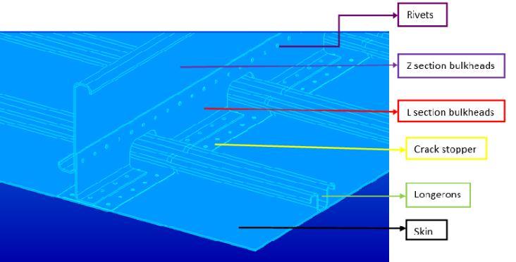
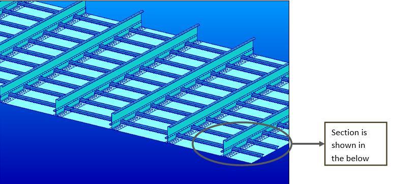
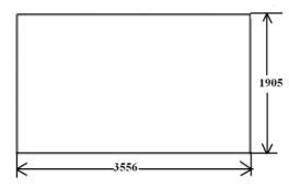
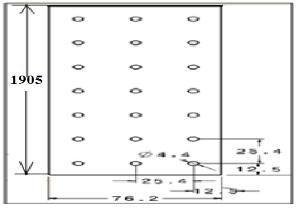
As the principal component of the fuselage to which allelementsareconnected,thestiffenedpanelasdepicted in figure 3.1 must be able to withstand bending moments, torsionalloads,andcabinpressurization.
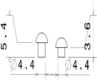
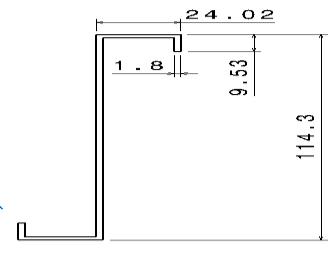
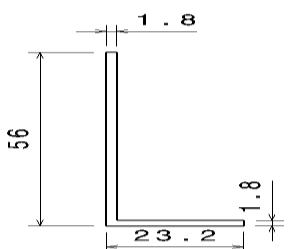
Intable3.1,thesizesandmaterialsofeachcomponent arelisted.Allmeasurementsaregiveninmillimeters.
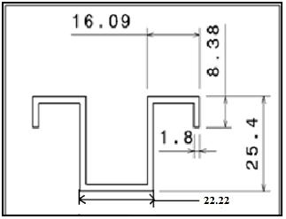

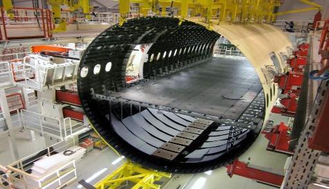
Thegeneralpartofthe fuselagesectionismadeup of stiffened panels. The fuselage is made up of several strengthened panels integrated together. The geometric model used for the analysis is the same as the actual fuselage stiffening panel. The meshing is done with the assumption that the curved panel is a straight panel for analysis purposes. The stiffened panel's numerous components are arranged geometrically as indicated in figures3.4to3.9.
3.2 ESTIMATION OF LOADS IN THE STIFFENED PANEL:
The fuselage of an aircraft structure is subjected to an internal pressurization in the range of 0-10 psi. Aircraft structureisgenerallycylindricalinnatureandissubjected tohoopstress.Asthestiffenedismodeledasstraightpanel thehoopstressesareconvertedintocorrespondingtensile stressesactingonthecomponents.
Hoopstressisgivenby
�� = (3.1)
The hoop stress is calculated by assuming the following values.
Cabinpressure,pi=6psi
Radiusofthefuselage,ri=1500mm
Thicknessofskin,B=1.8mm
�� =����.�������� ��
Forceperunitlengthi.e.theloadactingalongthelengthis calculatedby
Force per unit length acting on the skin, stopper and bulkheadarecalculatedbythefollowingequations:
(3.5)
3.3 FINITE ELEMENT ANALYSIS OF STIFFENED PANEL
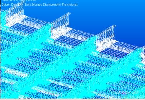

The stiffened panel's components are all made of aluminum2024 T3alloy.Table3.2 providesa summary of theAluminum2024T3'sproperties.
Table 3.2: MaterialpropertiesofAluminium2024T3
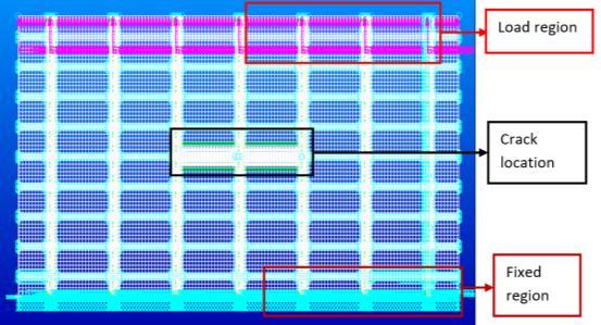
Thefiniteelementanalysisofthestiffenedpanelis carriedout usingNASTRAN solver.Meshingisdoneonthe components using quadrilateral and triangular shell elements.Thecrack isintroducedatthecenteroftheskin bydisconnectingthecommonnodesoftheelementsonthe crack front. The region near the crack tip is fine meshed with an edge length of 0.8 mm to avoid the stress singularity. The rest of the portion is meshed with coarse mesh.
Initially the structure is analyzed for a skin thickness of 1.8 mm and a central crack of 2a = 25.4 mm. Oneendofthestiffenedpanelwhichisparalleltothecrack isfullyconstrainedandtheotherendissubjectedtoloads asshowninfigure3.1
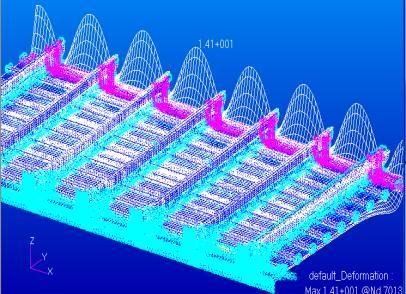
Assuming that the maximum damage occurs to the panel when the bulk heads are broken i.e. as the crack passes through the bulkheads. The broken bulkheads are modeled by deleting the elements in that region. The deformation plot of the above model is shown in figure 3.11 The plot indicates that there is a deformation in Z direction. In order to avoid bending of the stiffened panel, the deformation in Z direction needs to be constrained at allthenodesandthemodel isanalysedbyintroducingthe newboundaryconditionsasshowninfigure3.12.
3.4 SIF calculation using the MVCCI method for 1.8 mm of skin thickness
After the completion of the FE analysis, the modified virtualcrackclosuremethodisusedtocomputetheSIFof theloadedpanel,andtheresultsaretabulatedasshownin table3.3.
Table 3.3:SIFvaluesfordifferentSkinthickness
4 RESIDUAL STRENGTH OF THE STIFFENED PANEL COMPONENTS
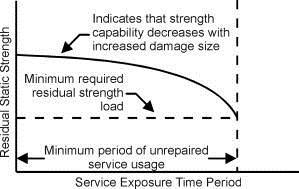
A fracture can have a major impact on a structure's strength, which is often much lower than the strength of the undamaged structure. One must assess the load carrying capability that will exist in the potentially fractured structure during its anticipated service life to avoid catastrophic failure. The residual strength of a cracked structure, which depends on the material toughness, crack size, crack geometry, and structural design, determines how much load the structure can support. As seen in Figure 4.1, the strength decreases as damagesizeincreases.Topermitunrestricted operational utilization, it becomes important to maintain limit load capability.
4.1 Residual Strength for Skin
Residual strength for skin is calculated by the following equation.

Where KIC is the fracture toughness of the material of the skin. KI is the stress intensity factor of the skin. σR is the remotelyappliedstress.
The calculation and tabulation of residual strength for a skinwiththreedifferentthicknessesisshownintable4.1.
4.2 Residual strength for bulkhead
Residual strength for bulkhead is defined by the equation 4.2.
(4.2)
Whereσu istheultimatetensilestrengthofthematerialof thebulkhead.σMax isthemaximumstressdevelopedinthe bulkhead.
The maximum stress developed in the bulkhead is obtainedbyperformingthefiniteelementanalysisandare tabulatedintable4.1.

Table 4.2: Maximumstressofbulkheadforvariousskin thickness
5RESULTS
5.1 Residual Strength for Skin
The variation of the residual strength with the crack length for different values of skin thickness can representedingraphicalformasshowninfigure5.1.
The residual strength of the bulkhead for various skin thicknessesisevaluatedbyequation4.2andare tabulated intable4.3.
Thevariationoftheresidualstrengthwiththecracklength for different values of skin thickness can represented in graphicalformasshowninfigure5.2.
6DISCUSSIONS
The residual strength fluctuation of the bulkhead and skin of a stiffened panel with regard to crack propagationandskinthicknessisshowninFigures5.1and 5.2. Figures 5.1 and 5.2 show that the residual strength of the skin and bulkhead decreases as the crack length increases. Due to the rise in skin thickness, the residual strengthhasalsoincreased.Forthesamecracklengthand thickness, skin has the least residual strength of the two components. Because of the load transfer from the skin to the bulkheads, the residual strength of the skin is somewhatincreasedinthatarea.
7CONCLUSION
The modified virtual crack closure integral approach used to assess the bulkhead's and skin's remaining strength in a stiffened panel produces reliable results. The methodology can therefore be used to assess theremainingstrengthofotherpartsofthestiffenedpanel.
REFERENCES:
[1] T. Swift, “Damage tolerance analysis of redundant structures,”Fract.Mech.Des.Methodol.AGARDLect.Ser.97, p.5,1979.
[2] P. M. Toor, “A review of some damage tolerance design approachesforaircraftstructures,”Eng.Fract.Mech.,vol.5, no. 4, pp. 837–880, Dec. 1973, doi: 10.1016/00137944(73)90054-4.
[3] J. Wiggenraad, P. Arendsen, and J. da S. Pereira, “Design optimization of stiffened composite panels with buckling
and damage tolerance constraints,” in 39th AIAA/ASME/ASCE/AHS/ASC Structures, Structural Dynamics,andMaterialsConferenceandExhibit,American Institute of Aeronautics and Astronautics. doi: 10.2514/6.1998-1750.
[4] N.K.SalgadoandM.H.Aliabadi,“Anobjectorientedsystem fordamagetolerancedesignofstiffenedpanels,”Eng.Anal. Bound. Elem., vol. 23, no. 1, pp. 21–34, Jan. 1999, doi: 10.1016/S0955-7997(98)00058-7.
[5] M.Adeel,“StudyonDamageToleranceBehaviorofIntegrally StiffenedPanelandConventionalStiffenedPanel.”
[6] S.Habeeb,“Crackarrestcapabilitiesofanadhesivelybonded skin and stiffener,” Thesis, Wichita State University, 2012. Accessed: May 04, 2022. [Online]. Available: https://soar.wichita.edu/handle/10057/5596
[7] F.CartaandA.Pirondi,“Damagetoleranceanalysisofaircraft reinforcedpanels,”Frat.EdIntegritaStrutt.,vol.5,no.16,Art. no.16,2011,doi:10.3221/IGF-ESIS.16.04.

