
STRUCTURAL BEHAVIOR OF RETROFIT BEAM COLUMN JUNCTION USING ANSYS
1Dept of Civil Engineering KKWIEER, Nashik (UG Student)
2 Dept of Civil Engineering KKWIEER, Nashik (UG Student)
3Dept of Civil Engineering KKWIEER, Nashik (UG Student)
4Dept of Civil Engineering KKWIEER, Nashik (UG Student)
5Professor, Dept of Civil Engineering KKWIEER, Nashik, Maharashtra

Abstract - The part of the column that is common to beam at their intersection in a building is known as the beam column joint. The fundamental purpose of beam column joint in reinforced concrete buildings is to transfer the load from connecting members effectively, while subjected to both gravity loads and seismic forces. The beam column joint is a portion that needs to resist lateral, longitudinal loads along with moment. They are the weakest link in RC moment resisting frame. Primarily due to the inadequate shear strength at the joints. In order to withstand these loads without causing damage, reinforced concrete frames must worksatisfactorily in extreme load conditionsatbeamcolumn junction. Thus, proves to be a crucial aspect of structural design. The use of carbon fiber reinforced polymer (CFRP) materials in the retrofitting of beam column joints is notable, due to its high strength,stiffness, and corrosion resistance. Ansys Workbench is a powerful software tool for analyzing and designing beam- column jointsinIndia.Itenablesdetailed simulations and analysis, reducing the need for physical testing and streamlining the retrofitting process. With its advanced features and rapid design iterations, it enhances project efficiency and reduces costs. The present study focuses on the analysis and retrofitting of beam-column joints using carbon fiber reinforced polymer (CFRP) materials in Ansys Workbench, in the 2022 R2 Student and 2022 R1 Teaching versions. The study highlights the Total deformation and Maximum principal stress of retrofitted Beam Column joints compared to their original condition.
Key Words: Beam column joint, Ansys Workbench, Carbon Fibre Reinforced Polymer, Shear strength, corrosion.
1. INTRODUCTION
1.1
The retrofitting of existing concrete structures has become an increasingly important aspect of structural engineering, particularly when it comes to enhancing the strengthanddurabilityofbeamcolumnjoints.Carbonfiber reinforcedpolymer(CFRP)jacketingisapopularretrofitting techniquethatcaneffectivelyincreasethestructuralcapacity ofthesejoints. In this report, we will explore the use of
CFRP jacketing in retrofitting beamcolumn joints and assessitseffectivenessinimprovingtheoverallstrengthand stability of the structure. We will also utilize Ansys Workbench software to perform Finite Element Analysis (FEA) simulations and gain a deeper understanding of the structural behavior before and after retrofitting. Furthermore,thisreportwillincludeadetailedcostanalysis of the retrofitting process, taking into account the cost of materials, labor, and project timeline to provide a comprehensiveunderstandingofthefinancialfeasibilityof thisretrofittingtechnique.
Thebeam-columnjointisoneofthecriticalelementsin reinforcedconcretestructures.Itconnectstheverticaland horizontalmembers,therebytransferringtheloadsfromthe slabandbeamtothecolumns.Thebehavior ofthebeamcolumnjointundervariousloadsisofutmostimportancefor thesafetyanddurabilityofthestructure.Theshape,size,and detailing of the beam-column joint have a significant influence on its performance.The integrity of the beamcolumnjointplaysavitalroleintheoverallstrengthofthe structure.Anyfailureordeformationinthejointcanleadto thecollapseofthestructure.Thereinforcementinthebeamcolumn joint is critical for its performance. The steel reinforcementprovidesstrengthandductilitytothejoint, enabling it to resist the forces induced by the loading conditions.Thedetailingofthereinforcement,includingits spacing,arrangement,anddevelopmentlength,iscriticalfor theproperfunctioningofthejoint.
1.3 Retrofitting:
Retrofitting of structures has become increasingly importantduetotheagingofinfrastructure,increasedloads, and changes in design codes. Retrofitting is the process of strengtheningor upgradingexistingstructures toimprove their performance under current and future loading conditions.Theretrofittingofstructuresinvolvesaddingnew elements or strengthening existing ones to improve their load-carrying capacity, ductility, and resistance to earthquakesandothernaturaldisasters.Retrofittingofjoints involves increasing the size and strength of the joint to
improve its load-carrying capacity and ductility. The retrofittingofbeam-columnjointsusingFRPwrapsinvolves wrappingthejointwithlayersofcarbonorglassfibersheets. TheFRPwrapactsasastrengtheningelementincreasingthe load-carryingcapacityandductilityofthejoint
1.4 Ansys Software:
Ansys Workbench is a powerful software tool widely used in the field of structural design and analysis. The software is particularly useful for retrofitting applications, allowingfortheaccuratesimulationofdifferentretrofitting techniquesbeforetheyare implementedinthereal world. AnsysWorkbenchoffersarangeofsimulationcapabilities, includingfiniteelementanalysis(FEA),staticanddynamic analysis,andotherrelatedsimulations.
1.5
Beam Column Joint analysis before andafter
retrofitting:
This report aims to study the behaviour of the beamcolumn joint under different loading conditions and to analyze the joint’s response before and after retrofitting usingAnsysWorkbench.Thestudywillfocusontheanalysis of the joint’s performance under seismic loads. The retrofittingofbeam-columnjointsusingdifferentmaterials andtechniqueshasbeenproveneffectiveinimprovingthe joint’s behaviour and enhancing the overall structural performanceofbuildings.
Thereportwillconsistofadetailedliteraturereviewof previous studies conducted on beam-column joints’ behaviour and retrofitting techniques. An overview of the analytical methods and modelling techniques used in the analysisofbeam-columnjointswillalsobe presented.The reportwillthenfocusonthesimulationofthebeam-column jointinAnsysWorkbenchandtheanalysisofitsresponseto seismic loads before and after retrofitting. The results obtained from the simulation will be used to evaluate the effectivenessofdifferentretrofittingtechniques.
2. METHODOLOGY
2.1 Material Specification:
Concrete:
ThegradeofconcreteusedisM25,whichishasstrength of25N/mm²achievedafter28daysofcuring.Theproportion of cement, sand, and aggregate used is 1:1:2, which corresponds to approximately 8 bags of cement, 4.4m³ of sand,and8.8m³ofaggregate.
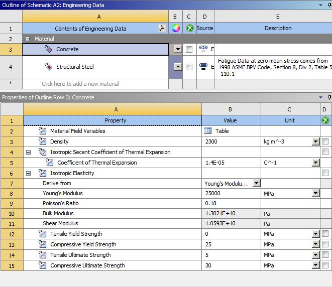
Thematerialpropertiesofconcreteusedinthisstudyareas follows:
ThermalConductivity:1.44W/mK
SpecificHeat:1000J/kgK
Density:2400kg/m³
CoefficientofThermalExpansion:1.2x10^-5/°C
IsotropicElasticity:Derivedfrom
Young’sModulus:30GPa
Poisson’sRatio:0.2
BulkModulus:38GPa
ShearModulus:15GPa
TensileYieldStrength:3MPa
CompressiveYieldStrength:25MPa
TensileUltimateStrength:4MPa
CompressiveUltimateStrength:30MPa
Structural steel:
ThestructuralsteelusedintheprojectisFe500TMT steel bars with yield strength of 500 N/mm² and an approximate elongation of 12%. This type of steel has high ductilityand tensile strength, which increases the efficiencyofthestructure.
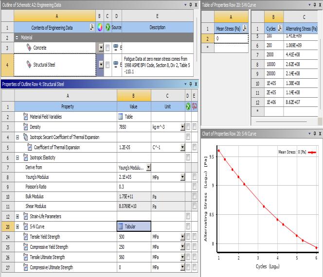
Density:7850kg/m³
ThermalConductivity:60.5W/m-“C
SpecificHeat:434J/kgC
NonlinearBehaviour:False
AssignedBodies:160
CoefficientofThermalExpansion:1.2E-05C^-1
Isotropic Elasticity: Derived from Young’s Modulus,whichis2.1E+05MPa
Poisson’sRatio:0.3
BulkModulus:1.75E+11Pa
ShearModulus:8.0769E+10Pa
Strain-LifeParameters:
TensileYieldStrength:500MPa
CompressiveYieldStrength:250MPa
TensileUltimateStrength:560MPa
CompressiveUltimateStrength:0MPa
Density:1800kg/m³
OrthotropicElasticity:
Young’sModulusinXdirection:2.3E+11Pa
Young’sModulusinYdirection:2.3E+10Pa
Young’sModulusinZdirection:2.3E+10Pa
Poisson’sRatioXY:0.2
Poisson’sRatioYZ:0.4
Poisson’sRatioXZ:0.2
ShearModulusXY:9E+09Pa
ShearModulusYZ:8.2143E+09Pa
ShearModulusXZ:9E+09Pa
Carbon Fiber Polymer:
Fiberreinforcedpolymers(FRPs)areanewtypeof lightweight, high-strength material that are non-corrosive. Theyaremadebycombiningathermosettingplastic,suchas epoxyorpolyester,withafiber,suchascarbonorglass.The useofFRPmaterialsisparticularlyeffectiveinimprovingthe stiffness and strength of structures. Carbon fibers, which contain 80-95% carbon and can be in either staple or filamentform,areapopularchoiceduetotheirlowdensity andhighstrengthandstiffnessproperties.
Creating Geometry in Ansys Space claim:
Step 1: Chooseastaticstructuralanalysissystem andselectthedesiredgeometryforanalysis.
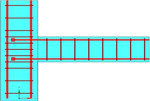
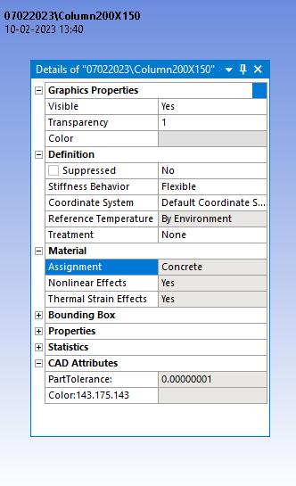
Step 2: OpentheDesignModelerwindowandselectthe unitofmeasurementasmillimeters.Then,selectaspecific planeandsketchtheexternaldimensionsofthecolumnin 3D.Namethisshapeas'Column200mmx150mm'.
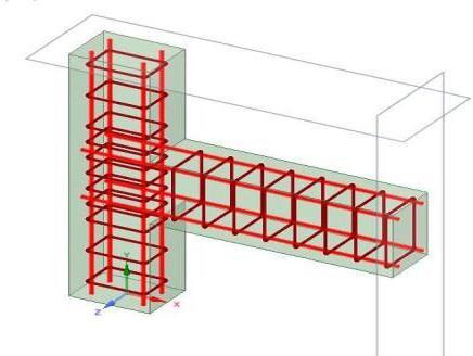
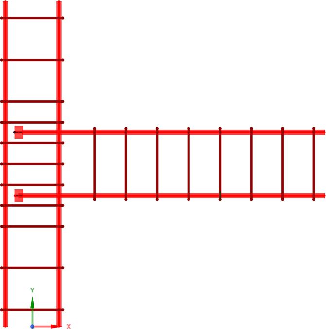
Step 3: Draw the main steel or longitudinal bars in the column by extruding circles with a diameter of 12mm. Move this shape to a new component named 'Circle'. Providea40mmcoverinredcolour.

Step 4: Next,sketchthelateraltiesforthecolumnwiththe name'Circle2'inamarooncolourandwithadiameterof 6mm.Createapatternforthetiestomeet therequired designspecifications.
Step 5: Similarly,createthegeometryforthebeamandits reinforcementwitha25mmcover.Createtwomodels:one withaheadandonewithoutaheadon thedevelopment bar.
1. Tocreatetheretrofittedmodel,extrudetheexternal dimensions and add awrappinglayerof1.25mmto thegeometry
Modelling and Analysis:

Step for RCC Structure:
Step 1: Assigning Material Properties: Set the appropriate units and engineering data, including selectingandspecifyingthematerialsfortheconcreteand structuralsteel.

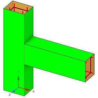
Step 2: Importing Geometry: Importthegeometryfrom SpaceClaim Design Modeller and open the model in ANSYSWorkbench.
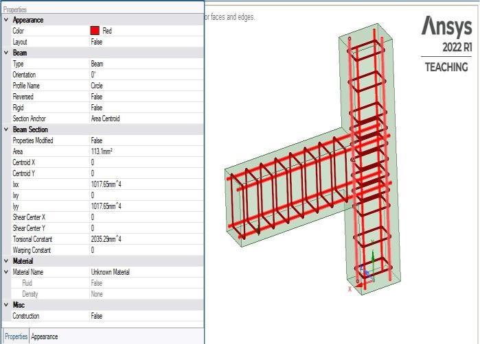
Step 3: Reinforcement Assignment: Choose all the line elements, and reassign them to structural steel. Additionally,setthemodeltypetoreinforcement,asthe beams serve as reinforcement components within the concretestructure.

(b)
Figure 14: Reinforcement Property Assigned
Step 4: Concrete Assignment: Click on the body of the structure,changetheassignment toconcrete,andaddthe correspondingcommandstodefinethematerialproperties for the concrete. This will ensure that the simulation accuratelymodelsthebehaviourofthereinforcedconcrete structure.
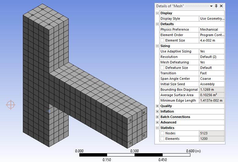
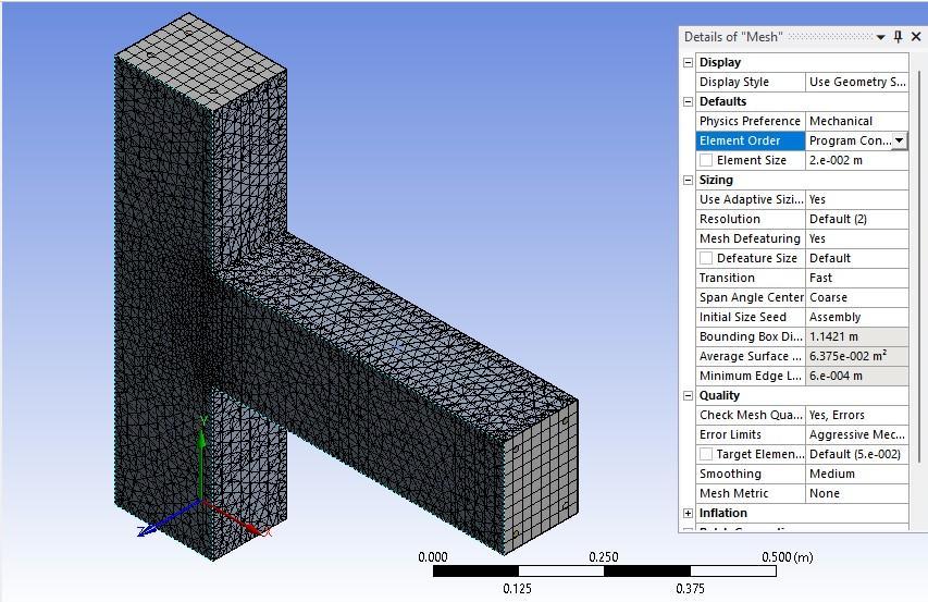
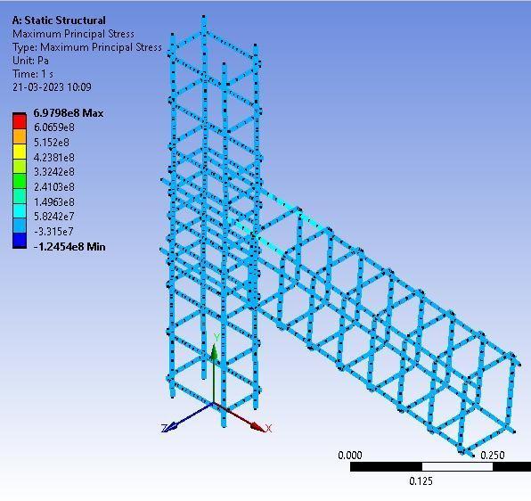
Step 5: Generating Mesh: Create a linear mesh with an element size of 40mm, 5123 nodes, and 1200 elements. This will enable the ANSYS Workbench software to analyzethe reinforced concrete structure efficiently and accurately.
(a)
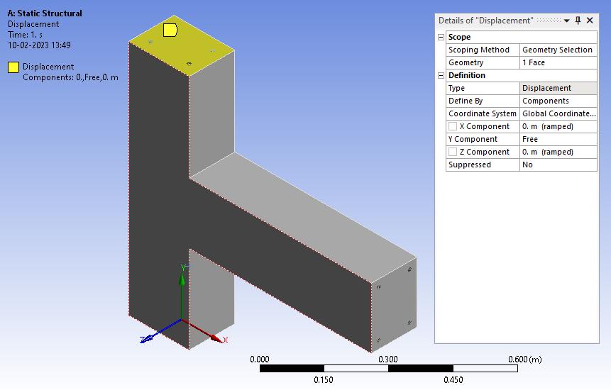
Step 6: Assigning Fixity: Configuretheanalysissettingsby selectingtheappropriateparameterssuchasdisplacement, force,andfixedsupportforspecificfacesoredges.Turnon the large displacements option to accurately model the behaviour of the structure under load. Set the boundary conditionsasfixedsupportatthebottomandhingedsupport atthetopface.
Step 7: Applying UDL: Applyaforceof80kN/minthe vertical direction (Y plane) as a uniform distributed load(UDL).Thiswillsimulatethestructure'sbehaviour underload.
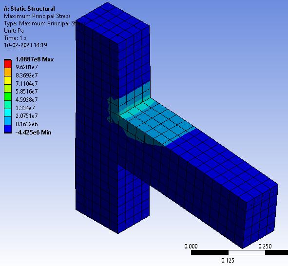
Step 8: Simulation: Clickthesolvebuttontoinitiatethe simulation.analyzethetotaldeformation, deformation of the reinforcement components, maximum principal stress,andmaximumprincipalstressonthereinforcement componentstoevaluatethestructuralperformanceunder load.
Step for Retrofitted RCC Structure:
Step1:Assigntheappropriateunitsandengineeringdata, including selecting and specifying the materials for the carbonfibreusedintheretrofittingprocess.
Step 2: Import the geometry from SpaceClaim Design ModellerandopenthemodelwiththeCFRPwrappingof 1.25mmappliedtothestructure.
Step3:Definethematerialpropertiesforthecarbonfiber and the existing structure, ensuring that the simulation accurately reflects the behaviour of the retrofitted structure.

Step4:Createatetrahedralmeshwithanelementsizeof 20mm,whichwillenableANSYSWorkbenchtoanalyzethe retrofittedstructureefficientlyandaccurately.
Step 5: Configure the analysis settings by selecting the appropriateparameterssuchasdisplacement,force,and fixedsupportforspecificfacesoredges.Turnonthelarge displacementsoptionifnecessarytoaccuratelymodelthe behaviourofthestructureunderload.
Step 6: Click the solve button to initiate the simulation. Analyze the total deformation, deformation of the reinforcement components, maximum principal stress, and maximum principal stress on the reinforcement componentstoevaluatethestructuralperformanceunder load.

Manual Calculation by IS Method:
As maximum allowable deflection δmax is greater than obtaineddeflectionδ,hencethememberis safeagainstdeflection.
Manual Calculation by EN Method:
BasedonthismethodthedeflectionδQP =1.68mm islessthanthemaximumallowabledeflection

δu =4.00cmi.e.40mm.
Therefore,thecheckissatisfied.
RESULTS AND DISCUSSION
Opening Remark:
The use of carbon fiber-reinforced polymer (CFRP)compositesinconstructionhasgainedconsiderable attentioninrecentyearsduetotheirexcellentmechanical properties and durability. One of the areas where FRP composites have shown promising results is in beam column joints, which are critical components in reinforcedconcretestructures. Inthisstudy,wecompare theperformanceofRCCbeamcolumnjointswiththatof CFRP beam column joints using Ansys. The aim of this comparisonistoevaluatetheeffectivenessofusingCFRP (Carbon Fiber Reinforced Polymer) composites as a strengthening technique for RCC (Reinforced Cement Concrete) beam-column joints. Thisstudy utilizes Ansys Workbench software to analyse and compare the structuralbehaviourofRCCandCFRP-strengthenedbeamcolumnjoints.
Results:
1) The results of this study show that CFRP wrappingcansignificantlyimprovethestrength andperformanceofbeam-columnjoints.
2) ThestudyfoundthatCFRPwrappingcanreduce deformationbyupto26.23%andincreasestress byupto6.41timesforModel1(withoutheaded bar), and can reduce deformation by up to 27.05%andincreasestressbyupto6.30times forModel2(withheadedbar).
3) These results suggest that CFRP wrapping is a viable and effective method for strengthening beam-columnjoints.

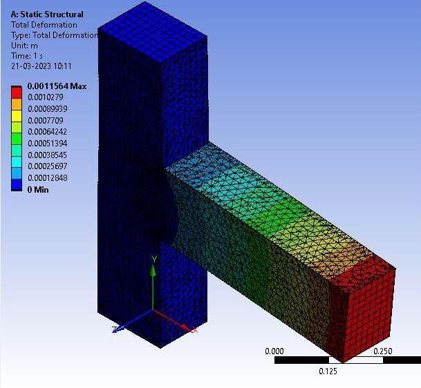
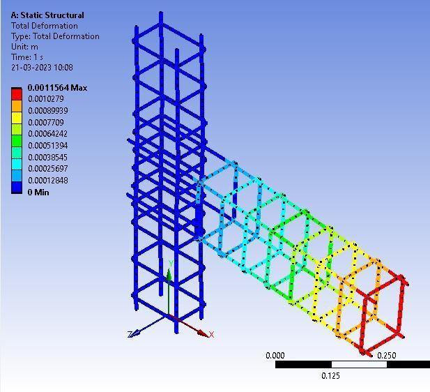
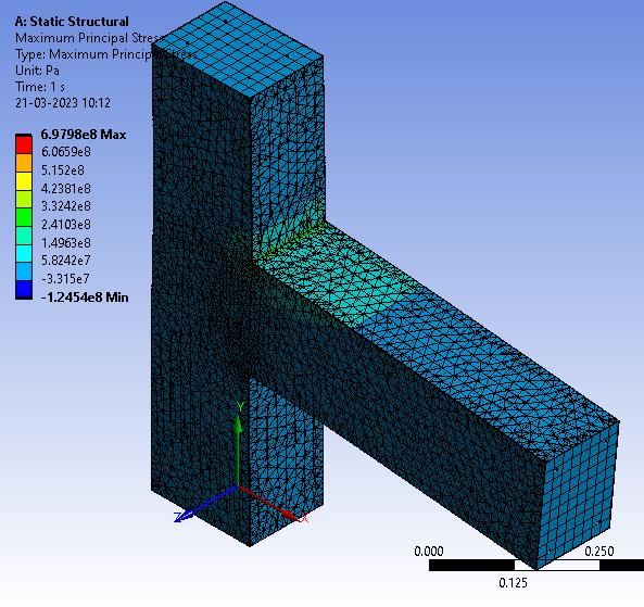
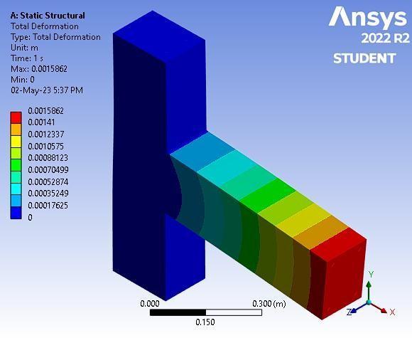
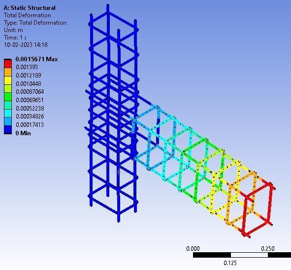
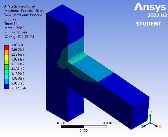
Figures 21-24 represent the analysis results of the concrete model withoutheaded bars. Figure 21 shows the deformationoftheconcretebody,andFigure22illustrates the deformation of the reinforcement bars. Figure 23 presentsthedistributionofmaximumprincipalstressinthe concrete body, while Figure 24 displays the maximum principalstressinthereinforcementbars.
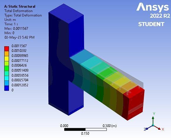
Figures25-28showcasetheanalysisresultsoftheCFRP model without headed bars. Figure 25 displays the deformationoftheconcretebody,andFigure26illustrates the deformation of the reinforcement bars. Figure 27 presentsthedistributionofmaximumprincipalstressinthe concretebody,whileFigure28showsthemaximumprincipal stressinthereinforcementbars.
Figures29-30depicttheanalysisresultsoftheconcrete modelwithheadedbars.Figure29showsthedeformationof theconcretebody,andFigure30illustratesthedistribution ofmaximumprincipalstressintheconcretebody.
Figures31-32representtheanalysisresultsoftheCFRP modelwithheadedbars.Figure31displaysthedeformation of the concrete body, and Figure 32 illustrates the distribution of maximum principal stress in the concrete body.

Cost Analysis:
It provides the results obtained for Model 1 (Without Headed Bars) and Model 2 (With Headed Bars) with and without CFRP wrapping. The table includes the Total deformationinmm,MaximumprincipalstressinMPa,%of Deformation regained, and the number of times Stress increased for each model. These results illustrate the impact of CFRP wrapping on reducingdeformationand increaseinthemaximumprincipalstressinbothModel1 andModel2ofthebeam-columnjoints.
The cost breakdown for the project is as follows: 0.0396 cubicmetersofconcreteisrequiredatarateofRs.11000 per cubic meter, resulting in a total cost of Rs. 435.6. For steel,5.1395kilogramsareneededatarateofRs.89000per metric ton, amounting to a total cost of Rs. 457.4155. Additionally,0.942squaremetersofformworkisrequiredat a rate of Rs. 1300 per square meter, totaling Rs. 1224.6. Demolitionworkwilltake1dayatarateofRs.2000perday, withacostofRs.2000.Forlabor,5daysareneededatarate ofRs.650perday,resultinginacostofRs.3250.Therefore, theoveralltotalcostcomestoRs.7367.616.
The total cost breakdown for the project is as follows: 3 squaremetersofFRCP(FiberReinforcedCompositePanels) atarateofRs.1200persquaremeter,amountingtoatotal costofRs.3600.Additionally,0.5kgofadhesiveisneededat a rate of Rs. 1000 per kg, totaling Rs. 500. The cost of
hardenerisnotspecified.Forlabor,615daysofsemi-skilled laborarerequiredatarateofRs.2perday,resultinginacost of Rs. 1230. Furthermore, 650 days of skilled labor are neededatarateofRs.1perday,withatotalcostofRs.650. Thus,theoveralltotalcostcomestoRs.5980.
ThroughacomprehensiveanalysisusingAnsysWorkbench softwareandreferencingpreviousresearch,theobjectives weresuccessfullyachieved.Model1experienced6.41times increaseinMaximumPrincipalStressanda26%reduction in total deformation, while model 2 showed 6.30 times increase in Maximum Principal Stress and a 27.05% reductionintotaldeformation.Comparingtheperformance ofbothreinforcementpatternsbeforeandafterretrofitting, theMaximumPrincipalStressandDeformationwerenearly equal. Additionally, the average difference between analyticalandsoftware-basedresultswas5.4%.Thecostof retrofittingamemberusingCFRPwrappingwasRs.6000, while the cost for reconstructing a member was Rs. 7287.75.
References
1. N.NaveenaandM.Ranjitham,"NumericalStudy on Retrofitting of Beam Column Joint StrengthenedwithCFRP”,(2016)Volume3,Issue 7,pp. 914-920
2. Gupta N. &Dhiman P. & Gupta A., "Case Study: RetrofittingofanExistingResidentialBuildingby UsingShearWall",(2015)Volume2,Number7, pp.582-586
3. Han N. & Wang X. &Yue H. & Sun J. & Wu Y., "Structural Performance’s Optimally Analysing andImplementingBasedonANSYSTechnology", IOP Conference Series: Materials Science and Engineering, (2017) Volume-216, Issue- 1, pp. 20-33
4. Harsha G., "Retrofitting of Reinforced Concrete Beams using CFRP Jacketing", International Journal of Recent Technology and Engineering (IJRTE), (2019) Volume-7, Issue-6C2, pp. 652655