
Thermal analysis of conformal cooling channel in injection molding
Ankit Prasad Dwivedi1 Asst. Prof. Shailendra Kumar Shukla2Abstract Injection molding is a typical method for producing plastic goods because of its high productivity, efficiency, and capacity to be molded into a broad range of things. Using numerical simulation, this study examines how using conformal cooling channels in plastic injection molds differs fromusingconventionalcoolingchannel.Thepurpose of this comparison is to look into the benefits and drawbacksofusingconformalcoolingchannels.Thus, this study aims to utilize the flexibility and reduced constraints of additive manufacturing (AM) to develop a novel method of cooling. Step one in the process involves revamping the cooling system used in a mold for an automobile component (used by a company that collaborates in the present study). The most notable results include a decrease of about 10.6 % % in theamountofcooling timerequiredtoreach the extraction temperature; a decrease of about 23.3 % in the temperature of the part; and a decrease of about26.1%inthetemperatureofthemold.
Keywords: Injection mold. Plastic injection moulding. Conformalcoolingchannel.Additivemanufacturing.
1. Introduction
Injection molding technology is the most popular method of plastics processing for mass production. The injection cycle time is an essential indicator of the energy efficiency of the injection moulding process. Injectionmouldprocessesaredividedintofourstages –filling, pressurization, cooling and ejection. The longest oftheseprocessestakescooling,andtheshorteningand overall optimization of this process is the focus of this diplomathesis.Thecoolingprocessaffectsthequalityof the manufactured component, as the uneven cooling of the component causes different shrinkage and residual stress in the parts of the product, therefore the cooling channelshaveaveryanessentialroleininjectionmould.
Cooling optimization in this work is done by comparingconventional methodssuchassimplerbored channelsversuscontourandconformalcoolingsystems. For optimal design, an injection mold including 3D model and drawing documentation is designed. Conformal cooling technology potentially achieves a uniform distribution of heat in the mold , reducing cooling time while ensuring high quality of the finished part.
Optimization of the cooling process is performed using CAE simulations in Autodesk Moldflow 2016. Cooling efficiency and manufacturability are included in the analysis. The analysis aims to compare conformal cooling technology to conventional methods. [1], [11], [9]
Injection Cycle
The injection cycle consists of several sequential processes.
Filling and plasticization: The material in the form of powder or granulate is fed into the hopper of the injection molding machine, where it is gradually heated to form a viscous melt. Before injection into the mold cavity, the melt has a uniform composition, density,viscosityandtemperature.
Injection: Under the influence of high pressure, the melt is fed into the mold cavity through the inlet system and through the nozzle of the injection moldingmachine.
packing: After a certain filling of the mold cavity, there is pressure when the screw of the injection molding machine moves slowly forward and exerts pressure on the melt in order to subsequently replenish the mold and reduce shrinkage injection moldedproduct.
Cooling: The injected product is cooled in the mold cavity to obtain the necessary hardness and rigidity andcanbesuccessfullythrownoutofthemoldbythe ejectionsystem.
Ejection : When the ejection temperature of the product is reached, the ejection system takes the productoutofthemold.
II.

Literature Review
Heat dissipation and temperature control system requirements
The heat transfer from the melt to the injection mold cavity is dependent on the thermal conductivity of the material used in the manufacture of the mold parts. Materials, such as. Copper and its alloys have many times higher thermal conductivity than steels and are
therefore able to dissipate heat many times faster. A temperature gradient is required for heat transfer, which practically means that the heat transfer rate can beincreasedbyplacingthetemperingchannelscloserto the mold cavity surface. However, the investment associated with the use of highly thermally conductive materials may not always be an effective solution. The reason is that heat transfer is not so limited by the conduction of heat through the form, but especially by the low thermal conductivity of the plastic and the limitedabilityofthetemperingmediumtoholdacertain amount heat. The use of highly thermally conductive materialsisinsomecasesefficientandrelativelyeasyto machine,butitcannotbesaidthattheyareuniversalthe bestsolution.Morecomplex temperingchannel systems require more complex machining methods, more complex procedures, sealing and maintenance. The design choice therefore remains whether investing in a more complex and expensive system is effective or whether a simpler solution is sufficient for the application[1]
Temperature control unit
Closed-circuit cooling and heating are controlled by temperature control devices with pumps with the possibility of power regulation. The pump output must be sufficient to ensure turbulent water flow in the injectionmoldchannels[2]
The water temperature control system is pressure-free at temperatures up to 95°C or overpressure at temperaturesupto400°C.[2]
Temperature medium
Water,air,oil,glycolsorsteamareusedasheattransfer medium. These tempering media flow through the formedchannelsintheform.Theytemperbothparts of themould(movableandimmobile)asneeded.[3]
Spiral Baffle system
The system of spiral partitions works on the same principle, but the secondary temperature control channel is divided into two turns. At the end of the partition, the temperature medium stream changes its directionandcontinueswithasecondthreadbacktothe main tempering channel. By using a spiral partition, an almost homogeneous temperature field is achieved in the adjacent area tempered by this system. The limiting factoristhesizeofthesecondarytemperatureductand manufacturersrecommendnotchoosingasystemwitha diametersmallerthan6mm.
III. METHODOLOGY
CAD Modelling:
Creation of CAD Model by using CAD modelling tools in solidworks for creating the geometry of the part/assembly.
Governing equation-
In this study, the fluids are considered to be incompressible, Newtonian (for water) or generalized Newtonian(forpolymermelt).Thegoverningequations for3Dtransientnon-isothermalmotionare:
Pre-Processing:
Import part/ insert geometry: importaCADmodel formouldanalysis.
Meshing: Cross section is a basic operation in moldingprocess.Inthisoperation,theCADgeometry is discretized into expansive quantities of little Elementandhubs.
Post processing.
Material Property: Choose the Material propertyformoldingprocess.
Processing: For viewing and interpretation of Result. The result can be viewed in various formats:graph,value,animationetc.
IV. Model Details
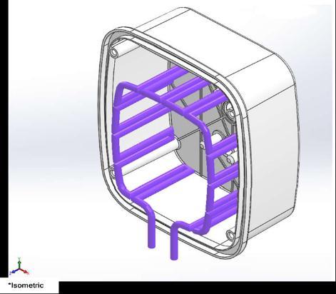
Figure5.1:Representationofthepartwith conventionalcoolingchannels
Table5.1:Conventionaldesigndimensions
Conventionaldesigndimensions
Channeldiameter 10mm
Distancebetweenchannelcenters 25mm
Distance between the center of the holesandthecavity 18mm
V. Results Part Cooling Time
The results of the simulations of the cooling time of the part are shown in Figures 4.1 and 4.2, for the conventional system and conformal cooling, respectively. It is observed that the cooling time was shortenedinthecoolingmodel,conformalcooling.
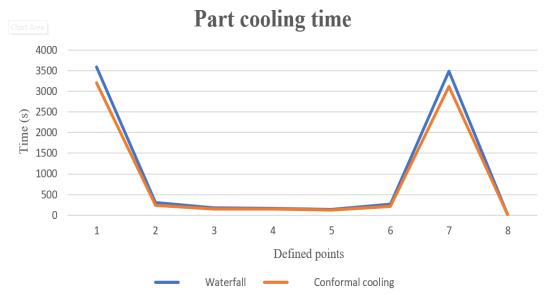
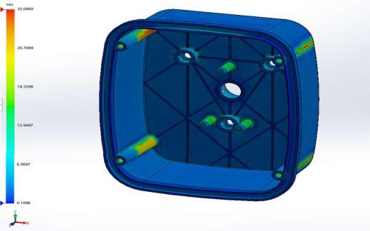
ObservingFigures4.1and4.2,itisobservedthat the part cooled by the conventional system presented the total cooling time of 35.89 seconds and for the part cooled by the conformal cooling system, presented the total cooling time cooling rate of 32.09 seconds,areductionof10.59%.Thepointsshownbythe closest color to red, are the points that took the longestcoolingtime.Figure4.3shows8pointsselected to establish a comparative analysis between the two coolingprojects.
In both cooling systems, the heating points with the long greatest cooling times are the same as expected due to the geometry of the part and the configurationoftheprojectedcoolingchannels.

Temperature at the end of the Cooling of the part
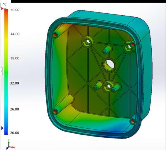
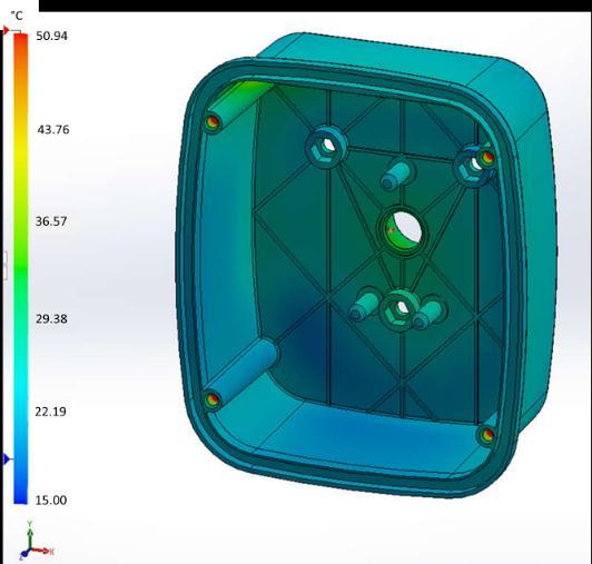
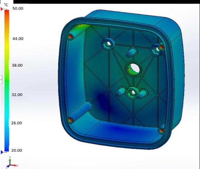
The results of the part temperature simulations at the end of the cooling cycle are shown inFigures4.5and4.6fortheconventionalsystemand conformal cooling, respectively. It is observed that the temperature presented greater uniformity in the refrigerationmodel,conformalcooling.
Thepointsshownbytheclosestcolortored,are thepointsthathadhighertemperatures.Itisnotedthat the part cooled by the conventional system presented a large area close to 50ºC (close to the yellow and red color), unlike the part cooled by the system which remainedbelow40ºC(closetoblue).
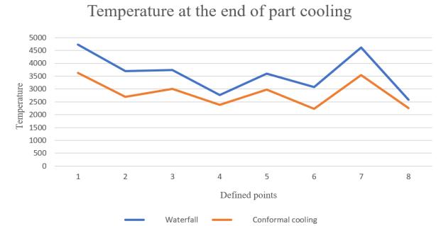
The data of the simulations referring to the temperatureinthepartdescribedthroughthe8(eight) points identified in Figure 4.3 are compared using Figure4.7.
It is noted that the temperature magnitudes for the conformal cooling system were lower and greater temperature uniformity was obtained when compared to the conventional system due to uniformity,positioningandwiderdistributionareaof refrigerationchannels,asshowninFigure4.7.
The temperature magnitude of the part was reduced considerably from the range of 25.79°C to 47.26°C in the conventional system, to 22.27°C to 36.24°C, in the conformal cooling system, a reduction in the highest value of 23.32%. The temperature variation in the part was also reduced, and in the conventional system the difference was 21.47°C, and in the conformal cooling system the difference was 13.97°C.

Mold Temperature at the end of the cycle
The results of the mold temperature simulations at the end of the part cooling cycle are shown in Figures 4.8 and 4.9 for the system conventionalandconformalcooling,respectively. Itis observed that the temperature presented greater uniformity in the refrigeration model, conformal cooling.
Thepointsshownbytheclosestcolortored,are thepointsthathadhighertemperatures.Itisnotedthat the part cooled by the conventional system presented a large area close to 50ºC (close to the yellow and red color), unlike the part cooled by the system which remainedbelow40ºC(closetoblue).
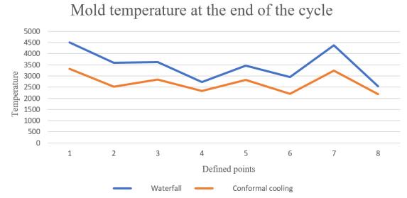
The data of the temperature simulations in the mold described through the 8 (eight) points identified inFigure4.3arecomparedusingFigure4.10.
homogeneousdistribution can also beobservedin the part. These factors ensure better quality of the molded product and lower possibilities of any defects arising from improper refrigeration, especially in the case of crystalline plastics such asPP.
The proposed refrigeration system aiming at manufacturing possibilities through the MA, demonstrated according to numerical simulation that the conformal cooling can reduce the cycle time and lowerthetemperaturesinthepartandmold, proving theimprovedresultofthisrefrigerationsystem.
References
[1]. AGAZZI, A. et al. Optimal cooling design in injection moulding process e a new approach based on morphological surfaces. Applied ThermalEngineering,vol.52,p.170-178,2013.
[2]. AKIN, J. E. Finite Element Analysis Concepts via SolidWorks. 1º ed. 303p. Rice University, Houston.WorldScientific:2009.
Thetemperaturemagnitudeofthemoldatthe end of the cycle, as shown in Figure 4.10, was reduced fromtherangeof25.39°Cto45.01°Cintheconventional system to 21.80°C to 33.24°C in the conformal cooling system,a reductioninthehighestvalueof 26.14%. The temperature variation in the part was also reduced, and in the conventional system the difference was 19.62°C, and in the conformal cooling system the differencewas11.44°C.
VI Conclusion
Based on the results discussed in this study, we thereforehavethefollowingconclusions:
1. The injection mold with conformal cooling type channelsprovidessignificantcoolingtimesavings of approximately 10.6% compared to the conventionaldrillingmethodstudied.
2. The temperature of the part and mold were reduced by more than 23% in the proposed conformal cooling method. The most
[3]. ALBERTI, E. A. et al. Additive Manufacturing: the role of welding in this window of opportunity. Welding&Inspection.SãoPaulo,v.19,n.2,p.190198, 2014. Available from: < http://www.scielo.br/scielo.php?script=sci_artte xt&pid=S010492242014000200011&lng=en&nrm=iso >. Access: 01 Oct. 2018. http://dx.doi.org/10.1590/01049224/SI1902.11.
[4]. ALTAF, K.; RANI, A. M. A.; RAGHAVAN, V. R. Prototype production and experimental analysis for circular and profiled conformal cooling channels in aluminum filled epoxy injection mould tools. Rapid Prototyping Journal, vol.19, n.4,p.220-229,2013.
[5]. ALTAF, K. et al. Determining the effects of thermal conductivity on epoxy molds using profiled cooling channels with metal inserts. Journal of Mechanical Science and Technology, vol.30,p.4901-4907,2016.
[6]. ASTM F3187-16. Standard guide for directed energy deposition of metals. ASTM International, West Conshohocken, PA, 2016. Disponível em: < http://www.astm.org/cgibin/resolver.cgi?F3187 > Acesso em: 14 set. 2018.
[7]. BAHNINI, I. et al. Additive Manufacturing technology: the status, applications, and prospects.TheInternationalJournalofAdvanced Manufacturing Technology, vol.97, p.147-161, 2018. https://doiorg.ez67.periodicos.capes.gov.br/10.1007/s001 70-018-1932-y.
[8]. DEBROY, T. et al. Additive manufacturing of metallic components – Process, structure and properties. Progress in Materials Science, vol.92, p.112–224,2018.
[9]. DIMLA, D.E. et al. Design and optimisation of conformalcoolingchannelsininjectionmoulding tools. Journal of Materials Processing Technology, vol.164–165,p.1294–1300,2005.
[10].DOWDEN, J. The Theory of Laser Materials Processing: Heat and Mass Transfer in Modern Technology. Berlin: Springer Science & Business Media,2009.
[11].FLYNN, J. M. et al. Hybrid additive and subtractive machine tools – research and industrialdevelopments.InternationalJournalof Machine Tools & Manufacture, vol.101, p.79–101,2016.
[12].GORNI,A.A.Introductionto rapidprototypingand itsprocesses.IndustrialPlastic,p.230-239,2001.
[13].GROOVER, M.P. Fundamentals of modern manufacturing: materials, processes, and systems. 4thEdition.JohnWiley&Sons,Inc;2010.
[14].GUILONG, W. et al. Analysis of thermal cycling efficiency and optimal design of heating/cooling systems for rapid heat cycle injection molding process. Materials & Design. 2010, vol.31, n.7, p.3426-3441. DOI: 10.1016/j.matdes.2010.01.042.
[15].HARADA, J. Thermoplastic injection moulds: basic designs and principles. São Paulo: Artliber, 2004.
[16].ILYAS, I.P. Production of plastic injection moulding tools using selective laser sintering and high speed machining. Tese (doutorado em filosofia) - University of Leeds School of MechanicalEngineering,UK,2007.
[17].JAHAN, S. A.; EL-MOUNAYRI, H. Optimal conformalcoolingchannelsin3Dprinteddiesfor plastic injection molding. Procedia Manufacturing,vol.5,p.888–900,2016.
[18].KITAYAMA, S. et al. Multi-objective optimization of injection molding process parameters for short cycle time and warpage reduction using conformal cooling channel. International Journal of Advanced Manufacturing Technology, [s. l.], v. 88,n.5–8,p.1735–1744,2017.
[19].KUO, C.; XU, W. Effects of different cooling channels on the cooling efficiency in the wax injection molding process. The International Journal of Advanced Manufacturing Technology, vol.98(1),p.887-895,2018