Design and Development of Valve Lapping Machine
ABSTRACT: Automobilemodernizationplaysasignificant part in the vehicle manufacturing industry and, also main source of income to the business. Currently, Internal CombustionEnginemaintenancecanbetermedasthemost crucialpartinvehiclemodernizationandthevalvelapping process which is put in this research which is done all throughICenginemaintenance.Thepresent-daytechniques utilizedinmostautomobileorganizationsforvalvelapping arenotproductiveandspendalotofoperatinghours.'Valve lappingMachine’forInternalCombustionEngine,isatool whichismappedout tovanquish theseproblemsthrough minimizing/reducing the human interference during the process.Theresearchincludesthe reportofdesigningthe device,methodologiesthatareutilized,resultsreceivedby usingfacts&analysisso,thatwecanenhancethedesignand designofthevalvelappingsystem.Lappingisamachining mechanismwherein,twosurfacesarerubbedtogetherwith anabrasiveamongthem,viahandmotionorusingasystem. This can take two forms, the first form of lapping (traditionally called grinding), involves rubbing a brittle materialwhichincludesglasstowardsaflooralongwithiron orglassitself(alsocalledthe"lap"orgrindingtool)withan abrasivealongwithaluminumoxide,optician'srouge,silicon carbide,etc.,inbetweenthem.
Keywords: Maintenance, Engine Cylinder, Valve Lapping Machine, Engine valves

1. INTRODUCTION:
Theapproachofvalvelappingisputintoeffecttoobtainthe flawlessseatofvalveinvalvesittingarea.Valvelappingor themannerofcreatingaseatinallyingvalvesofengine&the interrelated valve-seat area within the IC (internal combustion)enginehead(cylinderhead)isapieceofwork whichrequirestobeachievedveryperfectly.Thesignificance of obtaining a correct seat is that the air/fuel mixture (in petrol engines)orair(indiesel engines)is restrictedfrom flowingintothecombustionchamber,astheexhaustfuelis avoided from flowing to the exhaust manifold from the combustion chamber till the proper time. And, also a seat preventscondensationleaks.Thissystemofvalvelappingis usuallyconcludedwiththeusageofavalvelappingstickor anenergytool.As,bothtoolsarenotveryrobust,thosetools maybereplacedwiththehelpofthe'ValveLappingMachine
forInternalCombustionEngines',particularlysketchedfor thestrategyofenginevalvelapping.Themechanicaldevice will executeoneofakindofmotionindirectionsformerly carriedoutbyusinghands.Comparativelythevalvelapping deviceisveryeffectiveduetothefactthehumaninterference isverylimitedinthismethod.
The thought of inventing a system for the valve lapping systemcametous,whilewestudiedthattheconventional methodusedforvalvecleaningarenotgreenandadditionally time consuming. Engine head polishing and sustenance procedure plays an important role for proper working of engine.Thesystemofvalvecleansingapproximatelytakes1 hourtocompleteinclusiveoftestingofthevalveseathighquality using petrol. As, the conventional procedure is executedbyemployingavalvelappingstick,itisverytough andnotmuchefficient.Thisledustothinkhowbeneficialit could be if there can be a gadget that has a higher overall performanceoverconventionaltechniqueforvalvelapping.

1.1 LITERATURE REVIEW

M.R. Kumar Pratheesh et. Al [1] authenticated that Lapping is a finalizing process where material extraction takesplaceduetorelative/correspondingflowamongthe workmaterial,freeabrasivegrains,andthelappingplate. Thisprocedureisutilizedinaccomplishing finersurfaces and closer fits, and keeping near sufferance level. Even though, a sizable underlying science base exists about physics,mechanics,andthermaloutcomes.Lappingisbeen contemplated as an art, rather than a science. Hence exploringlappingatessentialdegreewillassisttoenhance itsusage.Thisdiscussestheresultsofthediversetechnique parameters influencing the material removal change and surface finish. This is finished by conducting a chain of experiments with the aid of varying the technique of guidelinesandcalculatingthematerialextractionrateand floorroughness.
S. M. Fulmali, et. Al [2] explained the Lapping method which is characterized by using its low speed,lowstrain, andoccasional material eliminationprice.Thismethodis usedinreachingthinsurfacesandcloserfits,correctionof imperfections, and keeping near tolerances. During the methodoflapping,themechanismsofsurfaceformationand elimination price are decisively influenced via the movement sort of the man or woman grains within the lapping abrasive. A gate valve is used to begin with and forestalltheflowoffluid.So,thewedgeandtheseatringofa valve are in continuous stress of fluid float and due to startingandremainingofvalvetheseelementsgetdepleted andtheyneedlappingatsomestageinrefurbishing.This paperwillsharetherequirementandapplicationoflapping duringthereconditioningofvalve.Thispaperwilldiscover themodern-dayoperatingconditionoflappingmachinein Automobileindustry.
Eraldo Jannone da Silva, et. Al [4] defined that the grinding manner is widely used to produce surfaces of properly dimensional accuracy and finish (Moulik et al., 2001). Besides these features, the grinding method must make sure that the designed mechanical system for the workpiece will no longer be negatively affected. During grinding,becauseofthechipformationmechanism,apartof the produced energy is converted into warmth and excessive temperatures are generated at the interface among the abrasive grain and the workpiece. These temperatures are the primary supply of damage at the machinedfloor(Shaw,1984).Itwasdiscoveredthatthermal stresses generated in the grinding system had been the primarycauseofthetensileresidualstresses(Chenetal., 2000), which motive a reduction within the carrier life understresscorrosionorfatigueconditions.Inmanycases, the thermal properties of the workpiece limit the productivenessofsuperiorgrindingmethods.
Prof. D. Kotkar, et. Al [3] confirmed that the method concernedofreachingproperseat,finersurfaces,nearerfits, correctionofimperfectionandpreservingneartolerances between engine valves and the corresponding valve seat areainsidetheinnercombustionenginecylinderheadisa taskwhichoughttobeaccomplishedveryaccurately.The importanceofsecuringaseatisthattheair/fuelaggregatein petrol engines or air in diesel engines is prevented from flowingintothecombustionchamber,equalastheexhaust gasoline is avoided from flowing to the exhaust manifold from thecombustionchamber until the proper time.And, alsoagoodseatpreventscompressionleaks.Theenginewill leaveitsperformancethroughlargeprobabilitiesifanyof thecircumstancesexplainedabovehappens.So,asthatisa very essential challenge in IC engine maintenance, extra interestisgiventothismissionbymeansoftechnicians.This methodofvalvelappingistypicallydonewiththeusageofa valvelappingstickorapowertool.Aseachofthesetoolsare notveryhighpoweredthesetoolscanbereplacedbythe' Valve Lapping Machine for Internal Combustion Engines', particularly designed for the strategy of engine valve lapping.Thesystememploysacompletelymechanicaland automated device which performs two one-of-a-kind motionsintwodirectionspreviouslyexecutedbyusinghand when the usage of valve lapping stick and power tool. Comparatively the valve lapping device could be very effective because the human involvement could be very limitedinthemethod.Authorconcludedthatthecapability andtheperformanceofthevalvelappingmachine,itsmiles hadtobedeveloped.

DIFFERENT METHODOLOGYADOPTEDFORENHANCING SURFACE FINISH OF CYLINDER HEAD:
Valve Lapping Stick: Valvelappingstick&handmotion Valvelappingsticksarethetoolsthatareusedtolapvalves byhandfluctuation.Thevalveisfixedtothesuckeratthetip
of the stick and lapping compound is put in before the operationstarts.Thisoperationtakesapproximatelyhalfan hourtolaponevalveofa3.0Lengine.
Grinding Machine: By holding valve against the grindingwheel,lappingcanbedonemachine-like.However, theoperatormustworkrepeatedly.Itwilltakelessthan25 minutes to lap a valve using the power tool. Power tool works using electric motor or pneumatically using compressedair.
Drilling Machine: Arubberbushislocatedatadrill-bit andoperationisaccomplished.However,theoperatormust workrepeatedly.
2. GOAL & OBJECTIVE:
Themainpurposeofthisprojectistodesignamachineboth efficientandeffectivethanformerlyusedmethodsforvalve lappingandtolessenthelaborcostbyreducingthehuman participation in the process. The objectives that had to be executedinordertoaccomplishthemaingoalwereplotting thebasicmodelofthemachine(structure),drawingthevalve lapping mechanism, building of the whole machine by designingthepartsneeded,calculatingandplottingthecam needed,inspectthedataandclassifytheminordertodesign five valve holding pieces, investigate data to obtain the requisition of the machine, seeking two high torque dc motorsthathasspecificRPM(revolutionsperminute)values anddeterminewhatmaterialsmustbeusedinorderforthe designtobelong-lastingandcost-effective.
2.1 SCOPE:
The purpose of this work is to advance a New Automatic operated Machineof ValveLapping. This idea allowsus to achieve our goal as well asbetter space management. The newmodelconsidersalltherealtimeconveyingsystemand furnishsolutionovertheirshortcoming.Thenewprototype willgivegoodcompetencecomparedtotraditionalmethod.
2.2 DESIGN OF MACHINE COMPONENT:
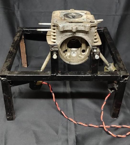
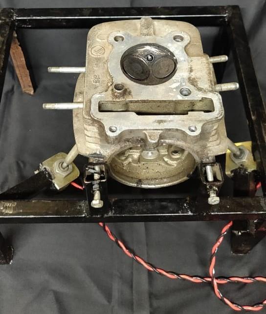
MachineFrame:Theentirefabricationisassembled onamachinebedandcylinderheadreclinedonit.
Particulars: MildSteel
Lapping Compound: Lappingcompoundisputin tothevalveseatbeforethestartoftheprocedure Lapping compound rub down the surfaces of the valve and the valve seat of the cylinder block levellingoutbothsurfacesandcreatingagoodseat. Alappingcompoundtubeusuallyhastwotypesof compoundsavailableinthetopendandbottomend independently. The two types named as fine and coarse.Technicianchooseswhichtypeofcompound
mustbeusedbynoticingthevalveseat.Ifthevalve seathasbeenunpolished,coarsecompoundisused. Otherwise,finecompoundisusedtoobtainaneven surface.
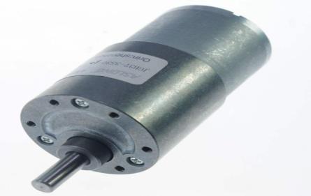
DC Motors: Two dc motors are used in valve lappingmachine,oneasthe drive forcamsystem andoneasthemotorforvalvelapping.

LowTorque:Volts12V,RPM-300
Reason:Highinitialspeedisrequiredtorunthecamfollower arrangement.
HighTorque:Volts-12V,RPM-30
Reason: High Torque is required due to opposition during LappingofCylindricalHead
3.1 SUMMARY
Theprocessofcreatingagoodseatbetweenenginevalves andthevalveseatareaintheICengineheadisataskwhich havetobedoneveryaccurately.Toobtainagoodseattheairfuel mixture (petrol engine)orair(diesel engine) mustbe preventedfromflowingtothecombustionchamber,similar asoftheexhaustgasispreventedfromflowingtotheexhaust manifolduntiltherighttime.Compressionleakscanalsobe prevented if good seat is obtained. If any of the above situationhappens,engine’sefficiencywillreducebyahuge percentage.So,itbecomesavitaltaskforthemaintenanceof IC engine. Valve lapping stick or a power tool are conventionallyusedfortheprocessofvalvelapping.Butboth of this tool are not much effective, instead Valve lapping machinecanbeusedtoobtainmuchsatisfactoryresults.The machineusesmechanicalsystemtoperformthetwomotions intwodirectionsreplacingthepreviouslytaskusinghandor powertool.Also,themachinefacilitatesverylimitedamount ofhumaninvolvement.
4.1 ACKNOWLEDGEMENT:
Wewouldliketotakethisopportunitytoexpressourdeep regardandprofoundgratitudetoDr.Prof.NanduDurgefor

hisguidance,constantencouragement,andvaluablefeedback throughouttheprojectwork.
We would also express our sincere gratitude to IETES BHARAT COLLEGE OF ENGINEERING and our engineering and technology department for providing us with the platformwherewecouldimplementourinnovativeideas.
5.1 REFERENCES:
1. M. R. Pratheesh Kumar: “Optimization of Process Parameters in Lapping of Stainless Steel”, International Journal of Engineering Research & Technology(IJERT),2013.

2. S.M.Fulmali:“NeedofLappingMachineforValve Component:ACaseStudy”,InternationalJournalof ModernEngineeringResearch.IJMER,Vol.2,Issue. 6,Nov.-Dec.2012pp4609-4612.
3. EraldoJannonedaSilva(2002).”TheInletEngine Valves Grinding Using Different Types of Cutting Fluids and Grinding Wheels”, Materials Research, Vol.5,No.2,187-194,2002.
4. Prof.D.Kotkar(2019),“DesignandDevelopmentof Valve Lapping Machine”, IJERT, Vol. 8 Issue 06, June-2019
