Robotic Tactile Sensor Probe used for Contour plotting of Weld Joint in Seam Tracking System
 Swati Omprakash Upadhyay1
1 BE, Department of Mechanical Engineering, Savitribai Phule Pune University, Pune, Maharashtra, India
***
Abstract - Welding is a process of joining two similar or dissimilar metals and it requires edge preparation to achieve full welding penetration. Generally, the edge preparation is done manually and many errors occur on the edge due to the handling of the workpieces. These errors in the edge preparation can make the welding process tedious and inaccurate and an arduous task for the welding torch to track the trajectory path to be welded. To accomplish welding operations correctly even in this inappropriate condition, industries are turning towards Robotic Welding Methods. One such Robotic welding system that comes under these methods is Seam Tracker, which is a system that plots contour points by tracking the welding seam line. This trajectory path helps in guiding the torch even in deflections due to deformities on the edge. Many industries are currently using a seam tracker which uses a laser sensor to track the seam line accurately, but due to its high cost and the presence of noise in the output data obtained, it doesn’t serve as a good investment for many small-scale industries. Therefore, industries are turning towards Seam Tracker which uses tactile sensors and is a more affordable welding system. A Probe tip is used as a sensor that rides over the weld joint and defines contour points for the welding torch. These contour points help in determining the correct trajectory for the welding torch. In this paper, the Sensor system of Seam trackers and the design and analysis of the probe tips of the tactile seam tracking system are elaborated.
Key Words: Tactile Probe, Seam tracker, Optical Seam tracker, Robotic welding system, Probe tip, sensors, position sensors,Touchsensors.
1. INTRODUCTION
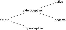
In this era of technology, manufacturing organizations need to boost their performance and upgrade their machines. To improve human productivity and product quality and to speed up the response to market demands, the method of Computer Integrated Manufacturing has been introduced. In CIM, Robots play a significant role in automation by performing a repetitive task which enhances the quality of manufacturing. [1] Robots can only function properly if the eventsare expected.However, whena robot experiencesanunexpected event,iteitherhaltstheprocessorcontinuesin the wrong direction. Both the operation reaction of the robot is not favourable, Hence a Robot should be provided with adequate information that is not provided in the teach-in phase. For this extraordinary information, it should be able to sensetheenvironmentoutsideitwiththehelpofsensors.Theusageofsensorsintherobotdependsontheapplicationof the robot in the industry. A variety of sensors are available in modern-day automation and robotic technologies. These sensors are characterized into two types; Proprioceptive and Exteroceptive robot sensors. Proprioceptive sensors are usedtoobtaininformationontheinnerstateoftherobotlikejointangles,angularvelocity, positionandorientationofthe toolcentrepoints,forcesandtorqueonthemanipulatorlinks. Theoutputdataoftheproprioceptivesensorsistheinput tothemotorcontrolsystemwhich receivesitssetpointsfromthemaincontrolsystem.Ontheotherhand,Exteroceptive sensors are used to analyze the environment of the robot or a manufacturing system. These sensors include Binary sensors, Scalar sensors, and Image sensors. Binary sensors include microswitches and reed switches, they provide informationbasedonwhichtheoperationcanbeinterrupted,started,orfinished.Anothertypeofelectroreceptivesensor is the scalar sensor which is used for the acquisition of metric information such as relative position, linear and angular velocity, acceleration, pressure, gripping force, optical properties, thermal properties, and magnetic properties. In Robotics,Optical,Acoustic,andtactileImagingisof majorpractical importance. Tactile andAcousticsensorsprove tobe lessexpensiveandhence,areusedinmanysmall-scaleindustries.OpticalImagingismajorlyusedinindustriesbecauseit provideshigh-qualityimagesbyusingaCCD(charge-coupleddevice)camera.
There has been much advancement in manufacturing technologies where a human worker is replaced with a welding robotsincerobotsproducemoreefficientandconsistentweldswithlesserror.Weldingisoneofthesignificantoperations of almost all manufacturing processes that resulted in numerous innovations in welding technology. Many welding operationsneedtobedoneinahazardousenvironmentwheremanualweldingcanputthewelder'slifeatrisk.Inaddition to this, many critical components need to be welded which requires very high focus and more time to be done. [2] [3]. Therefore, Mechanical Robots and motorized hardware play a major role to provide highly profitable production rates. Robotic welding leads to an increase in weld quality, adaptability, and a comfortable workspace. For many defects like weldgaps,impropersurfacefinish,improperfittingofaworkpiece,andin-processdefectslikethermaldeformitiesdueto welding and change in gaps, it is important to build a system that can inspect the defect and take corrective action. Generally,“TeachandPlayback”weldingrobotswereusedtoguidethetorchalongtheweldseampath,anothermethodis workpieces can be categorized according to their welding parameters, and considering these parameters different automatedweldingmachinescanbedevelopedforeachcategory.Theserobotsystemswerenotsuitableforchangeableor varyingweldingconditionsandmanytypesoferrorsoccurredsuchaspre-matchingerrors,assemblyerrors,andthermal deformationerrors.


Totrack the weldaccurately,itisnecessaryto obtaindetailedinformationabouttheweld,suchasthewidth,depth,and centerline of the weld. All these problems can be resolved by using a sensor for seam tracking and weld inspection. The addition ofsensorsintheautomatedweldingoperationtransformsthe robotinto anintelligentrobotthatcan recognize variousissuesandcoordinatewithsensorstoenhancetheefficiencyofthesystem.Theseintelligentrobotsworkwonders in welding operations, eliminating the difficulties for the human welder. For a variety of welding operations different roboticsystemsaredesignedanddevelopedandmoreresearchisbeingdone.
1.1 Seam Tracker
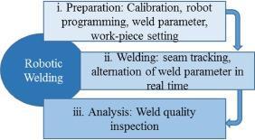
Onesuchweldingrobotictechnologythatiswidelyusedinautomatedweldingoperationsinindustriesallovertheworld isSeamTracker.ThisSystemimprovestheweldqualitybytrackingtheaccurateseampositionbyfeedingtheinformation tothecontrollerandprovidingaprecisetrajectorypathtotheweldingtorch SeamTrackerconsistsoftwomainprocesses asfollows:

a)SensingMechanism
b)ControllingSystem
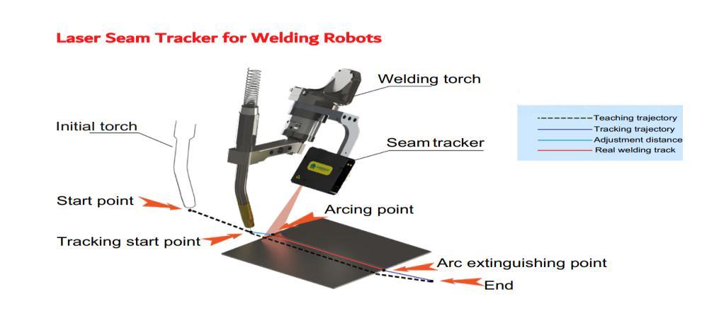
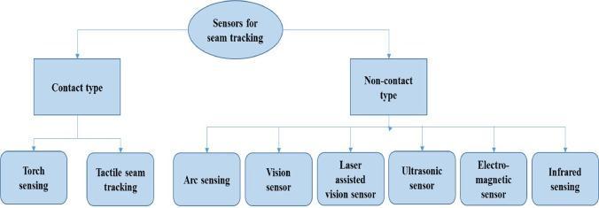
Anaccuratecontourplottingcanbeobtainedforthetrajectoryofthepathonlyifthesetwosystemsworkincooperation. Figure5 showsaSeamtrackingsystemusingaLasersensorasaninstancetoexplainthebasiccomponentsoftheSeam tracker. The Sensing Mechanism Consists of a single sensor or an arrangement of position sensors like a Capacitive displacementsensor,Eddy-currentsensor,Halleffectsensor,Inductivesensor,LaserDopplervibrometer(optical),Linear variable differential transformer (LVDT), Photodiode array, Piezo-electric transducer (piezo-electric). These Sensor systemstrackthecurvatureoftheweldseamjointandthedataofthecurvaturelikedepth,widthandthecenterlineofthe weld joint is sent to the control unit. The control unit consists of the motor drives, PLC, connecting cables, and power supplies.Thecontrolunitrespondstothedeflectionsthataresensedbythesensorsofeachaxisandcorrectiveactionsare performedaccordingly.
Theseamtrackinghasbeenevolvingoverseveralyears:
1.FirstGeneration:Two-passweldingsystemwasused,wheretheweldseamwastrackedbythesensorinthefirstpass andthetorchwasoperatedtoweldtheseamlineinthesecondpass.
2.SecondGeneration:ThisgenerationofSeamTrackersusedthereal-timescanningtechnique,wherethetrackingofthe seamlineofthejointandweldingtorchwereoperatedsimultaneously.
3. Third Generation: This generation of seam trackers also used Real-time Tracking with the addition of obtaining Informationaboutvariationsintheweldseam.
Othermethodsbywhichseamtrackingcanbeclassifiedarethetypesofsensorsusedorthemethodusedfortracking.

2. OPTICAL SEAM TRACKER
Formanyyears,researchershavebeenexperimentingwithSeamtrackersusingadifferentvarietyofsensorstoget an accurate and uniform weld by tracking the weld seam line accurately [4] [5]. Optical sensors have proven to be very efficient,whereaCCDcameraisusedtocaptureanimageandthedatarequiredforguidingtheweldingtorchisextracted from it. In this paper [6], due to the difficulty in detecting the weld pool position during the arc welding process, the KalmanfiltermethodwasproposedwheretheweldingimagesfromtheCCDcameraareanalyzedandthecentroidofthe weldpoolimagesisextractedastheeigenvectoroftheweldposition.Thiscentroidrepresentstheweldpositionrelative to the welding torch. This method also helps in detecting the centroid measurements that are not consistent with previously taken data of centroid measurement and the desired weld trajectory measurement, hence it turns out to be very precise in detecting the weld position. [7] However, the algorithm detects the weld seam position from the twodimensional image plane was not accurate, which thereupon made the system very complicated and time-consuming. Weldparameterslikeweldgroovedepth,weldgap,anddetailedshapeconditionweredifficulttoextract.Toresolvethis issue, researchers suggested utilizing the laser sensor along with a CCD camera. A Laser Optical sensor consists of three main components as follows; laser diode, CCD camera, and filter. The CCD camera and laser are kept at some angle to capture the projection of the laser on the workpiece properly. The captured data is sent to the controller unit. A control unitthenanalysesthedataanddefinesatrajectoryfortheweldingtorch.Oncethetrajectoryisplannedbythecontroller, the welding torch is allowed to follow the path of the trajectory. After numerous tests and trials, Optical seam tracking technologyprovedtobeveryefficientandaccurate.Consequently,manylarge-scaleindustriesareusingthisautomation technologytoboosttheirproductionrateandmanufacturepartswithuniformweldments.
2.1 Controller design
The data obtained from image processing are then sent to the control unit of the seam tracking system to guide the weldingtorchalongtheseamweldtrajectory.Therehavebeenmanyinnovationstakingplaceinthecontrollerdesignto align the torch with the weld seam line accurately. The author in [8], proposed the control design where the robot was

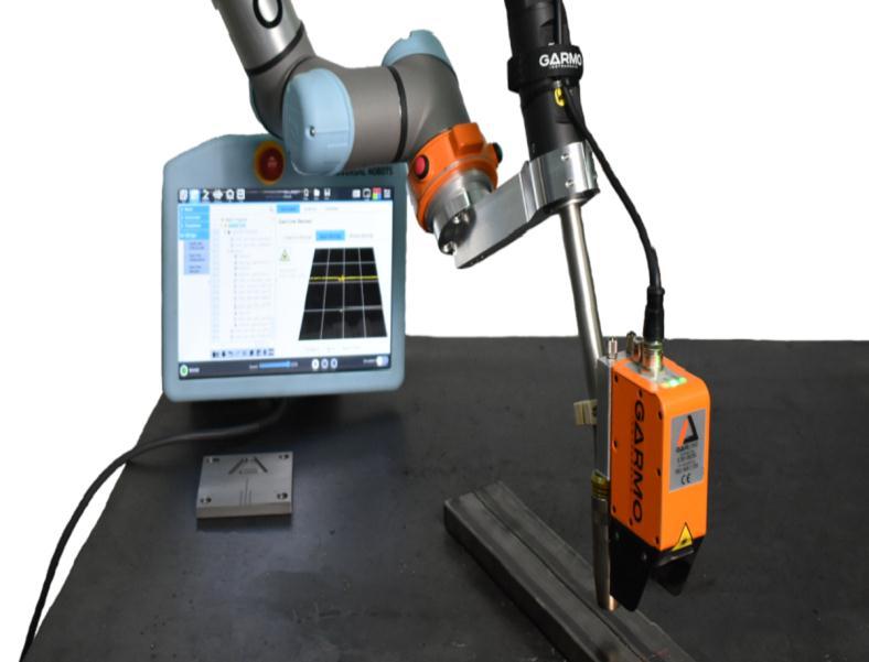
guided by the laser stripe sensor to the seam path trajectory. To remove errors, a control mechanism using a PLC to control a stepper was designed by the author [9]. After conducting several experiments the author [10] proposed a PID (Proportional-Integral-Derivative)controllerinthecontrolunitofthelaserseamtracker,whereoffsetvalueandrectifying voltagearetakenintoconsiderationasinputandoutput.
2.2 Advantages of Optical (Laser) sensor
1. Trackingisveryreliable
2. Highspeedcanbeachieved
3. TrackingisnotaffectedbyWeldsettings
4. Functionsoftheweldingareadaptable:SpeedandWeldsettings
2.3 Disadvantages of Optical (Laser) sensor

1. ThedepthoftheV-Jointoftheshinymetallikealuminiumcannotbedetermined
2. HighComplexity
3. HighCost
4. Trainingonthesystemisrequired
5. ThesensorismountedontheTorch,whichleadstotherestrictiontothejointaccess

6. Outsidelightinterferencecanaltertheperformanceaswellastheresultsobtained
Although the Optical sensor has many advantages, this system cannot be used by small-scale industries because of high capitalinvestmentandisdifficulttoreplace,asaninappropriatedatasettingmightcauseseverelosstotheindustryand its production. In addition to the high cost, shiny metals like Aluminium cannot be welded using Laser or Optical sensor technology. The data fetched by the controller can also get affected by the external light, which results in inaccurate results.Ithasbeenobservedduringtheexperimentsthattheimageacquisitionwasaffectedbythearcandspatterduring the welding process. Mota et al [11], showed that the effects of arc and spatter can be eliminated by using High power illumination lasers and optical filters. But the high brightness of the high-power laser can cause damage to the person operating it and can also get overexposed to the camera. Therefore, it becomes difficult to locate the seam feature point fromtheunclearimageisoneoftheissues.[12]AuthorYongZouproposedaCCAN-basedweldingimagemethodtosolve a problem of interference caused by arc and spatter in welding seam technology. This method helped in preventing the drift phenomenon in the welding seam tracking. This method also enhances the stability of tracking systems which improves welding accuracy. The author Y. Zou the paper [13] shows a new method based on the passive light vision technique,wheretheimageiscapturedbyaCCDcamera.Toobtainthedeviationbetweentheweldgrooveandweldtorch anarrowbandfilterisused.Thenoiseiseliminatedbythemedianfilterandwavelettransformandthedetailsoftheimage are obtained. This deviation of the welding torch from the centreline of the groove can be used in the Seam tracking of robots. In the paper [14] the author brings up the semi-autonomous robotic weld system, in which the vision sensor calculatestherobotweldtrajectoryandweldparametersbyusingtheinbuiltdatawhichiscollectedbyscanningbyvision sensorin3DCADdrawing.Thisapproachreducestheneedforprogrammingroboticweldparametersforeachpart.The datacanberefinedbyusingtherobotteachpendantaftertransferringthedatatothecontrolunit.Apreciseanduniform
weldseamisobtained whichincreasestheproductivity oftheroboticsystem.Inthispaper [15]Thelaserseamtracking methodisintroducedcategorizingitinto4stepsasfollows:
1) Detectionoftheinitialandtheendpoints
2) Detectionoftheedgeoftheweld
3) Measurementofthewidthofthejoint
4) Determiningtheweldingpathconcerningthepositionoftheweldingrobot
[15] The noise in the data is eliminated by the filtering mechanism and The result obtained by using all these 4 steps is verysatisfactory,reducingtheerrorsbyprecisepositionandaveragedeviationupto38.38%and41.71%respectively.
Tohaveauniformweldthroughoutthetrajectoryacquiredfromthecontourpointsonthejoint,thedataobtainedshould beerrorless.Tocircumventthesecomplications,aTactilesensingtechnologyhascomeforthtomakethistechniquemore reliable.

3. TACTILE SEAM TRACKER
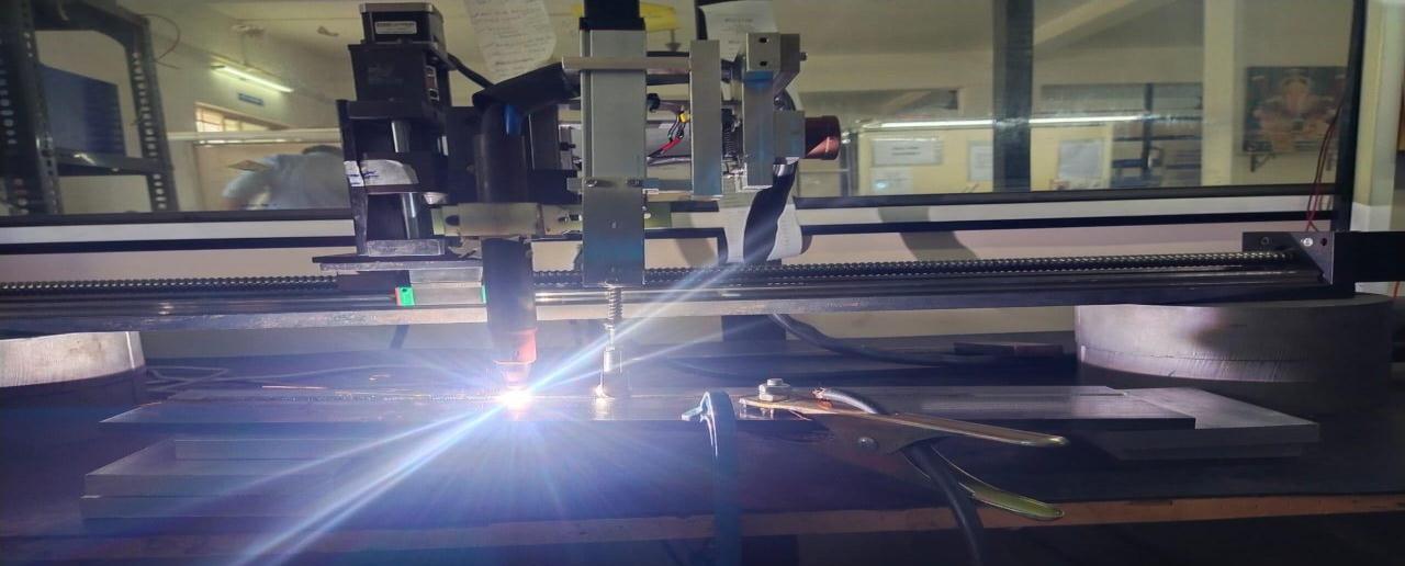
Tactile Seam Tracking Technology acts as an alternative solution by replacing the laser-based sensor with a fully automated mechanical sensor system. Similar to the Optical Seam Tracking System, Tactile sensors consist of two main subsystems namely Sensing Mechanism and Control Unit. Instead of the Laser sensor used in Optical Seam Tracker, a Tactile sensor is used which rides a probe tip and at the same time it also detects the deviation at the edge it touches, simultaneously sending the data of the contour plotting of the Trajectory to the control unit. Hence, this process is a closed-loopsystem. AsignalfromthecontrolunitisthensenttotheCrossslides.CrossslidesconsistofslidesinX,Y,and Zcoordinates,whosemotionsarecontrolledbyservoandsteppermotors.TheCrossslidearrangestheslidesinallthree directions to sync with the Trajectory path defined by the contour plotting done by the tactile sensor. As per the data obtainedbycontourplotting,aweldingtorchissenttofollowtheplottedtrajectoryandhenceauniformandevenweldis obtained.Itwasanalyzedthatmechanicalsensorsmightprovidesimilarseamtrackingwithaccuracyandprecisionasthat laser sensors. These mechanical sensors are not just economical but also quite compatible with industries at all levels of production.
3.1 Selection of sensors
Thetactileseamtrackingtechniqueusesaprobethatsensesadeflectionandalignstheweldingtorchatthe centreofthe weldseam.Thedeflectionsintheprobeareinallthree-dimensionalcoordinatesX,YandZ.Todetectthedeflectioninall threedirections,anarrangementofmechanicalpositionsensorsareused.ThesesensorscanbeaLinearpotentiometer,an encoder,LVDT,etc.Refertosection1ofthepaper.
3.2 Selection of Cross slides
Theselectioncriteriaforthecrossslideareasfollows:
1) Dimensionoftheselectedjoint
2) Determiningthestrokelength
3) Payloadrequirement
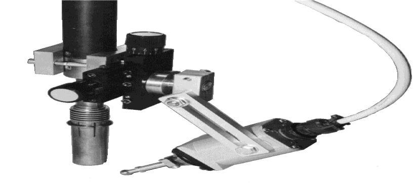
Thestandardslidesthatareavailableinthemarketare:
1) ST40
Thepayloadcapacityof18kg Strokelengthof8cm*8cm
2) ST250
Thepayloadcapacityof113kg Strokelengthof13*13

3) ST450
Thepayloadcapacityof204kg Strokelengthof25*25
The initial step in the selection criteria of the cross slide is to determine the dimensional range in which the joint of the componentistobewelded.Thedimensionalrangeofthejointhelpsustoascertaintheminimumandmaximumdeflection thatcantakeplace.Theapproximateknowledgeofdeflectionthatmightoccurinthestrokelengthrequiredforthecross slide can be anticipated. The next step is to determine the payload required. If the desired payload and stroke length is known,thelegitcrossslideisselectedamongthestandardcrossslidesavailableinthemarket. Figure10showsthecross slidesfortwodirections.
3.3 Selection of motors

Afterthedatafromthesensingmechanismistransferredtothecontrolunit,theControlunitadjuststheX,YandZslides ofthecrossslidetoaligntheweldingtorchinthecentreofthejoint.Thisadjustmentorthemovementofthecrossslideis donewiththehelpofmotors.Generally,theServomotorandsteppermotorareused.Figure11showsthemotorsusedto movethecrossslidesinTactileSeamTracker.
3.4 Design and Analysis of probe
The paper aims to plota contour and define a trajectory for a Tactile Seam tracking system to enable precise welding operation.Duringtheoperatingconditionstheprobegoesthroughmanydeformationsincludingstaticstructuralduetothe loads on the components, frictional contact between the workpiece and the probe, and thermal deformation due to the welding temperature. The probe has to be strong enough to sustain the real-time deformation taking place while the weldingoperation.All thesedeformationsmayreducethelifeoftheprobe,whichmightaffecttheoverall performanceof the machine system. To get precise real-time contour plotting, the deformations need to be minimized and the cross-
sectional dimensionoftheprobeshouldbemaintained.So,itisveryimportanttodesigna probethatismoresustainable and has a good life expectancy. Therefore, an Analysis of the probe is done to analyze stresses, Deformation, Factors of safety,Equivalentstress,andLife,andaccordingly,thedesignoftheprobeismodified.
3.4.1 Design parameters
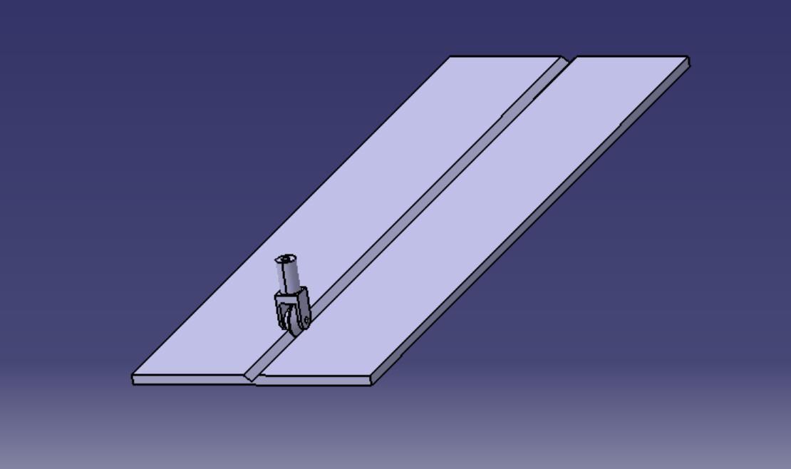
AVgrooveofanexpectablesizeof8mmdepthwitha30-degreeangleisconsideredandaprobeisdesignedasperits dimension.BoththeprobeandthejointaredesignedintheCADsoftwarecalledCATIAandtheanalysisisperformedonthe CAE software called ANSYS. Numerous types of probes can be used for contour plotting but for this paper we are consideringrollerprobes. ThedesignoftherollerprobewillbemodifiedafteranalyzingtheresultsobtainedfromANSYS andasuitabledesignwillbechosenforthesystem.

3.4.2 Material Selection
Afterexaminingthehardness,thermalcoefficientofLinearexpansionandcorrosionresistance,SS431wasselected.SS431 has its application in the manufacturing of bolts, shafts, pumps, propeller shafts and in laboratory appliances.The 400 series of stainless steels have higher carbon content, giving it a martensitic crystalline structure. This provides high strength and high wear resistance.ThechemicalandMechanicalpropertiesofSS431areasfollows:
Table1: Mechanical Composition of SS431
3.4.3 Meshing
After the geometry is generated, the 3D model of the probe meshes with an element size of 1mm. And the workpiece
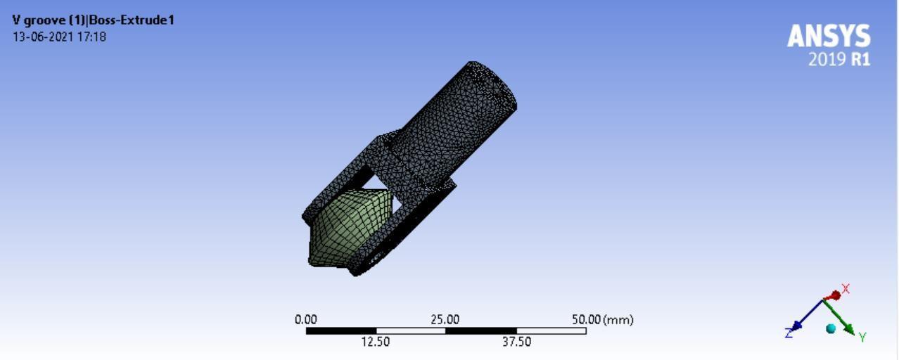
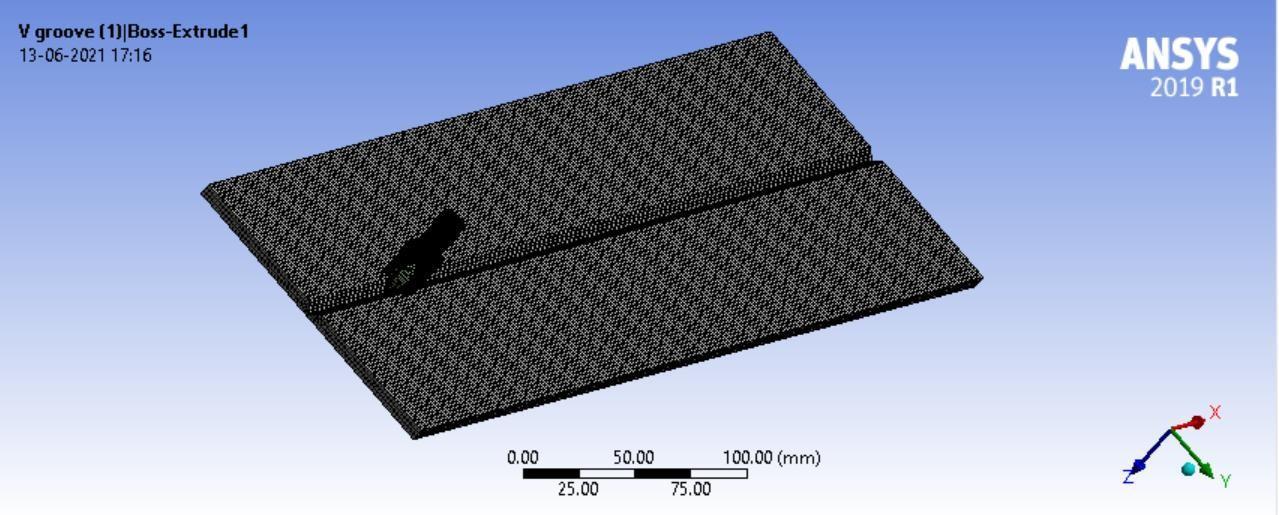
meshedwith
3.4.4 Steady State Thermal Analysis
During the welding conditions, thermal stresses are induced in the probe due to the contact between the probe and the workpiece and also due to the heat of the welding torch. These thermal stresses may cause the probe to deform, which might affect the sensing mechanism of the system. Data obtained from a deformed probe will not be accurate, hence it ll

affectstheefficiencyofthewholesystem.Steady-statethermalanalysisshowsthedistributionofstressonthecomponent andthedesigncanbemodifiedlater
Temperature constraints:
After discussingthe practical operatingparameterswiththeindustryfromthedomainof welding automation,theinitial temperature of the workpiece is 200 ℃ and the conventional temperature on the probe is 22 ℃ Figure 15 below shows theinitialtemperatureconstraintsgiventotheprobeandworkpiece.
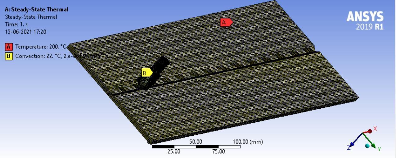

Results:
InFigure16 below,itisobservedthatthemaximumstressattherollingsectiontipoftheprobeisduetothermalstress induced due to heat transfer during welding operation which is observed to be 182.67 C. The minimum temperature observedis43.999C.Maximumstressisattherollersectionoftheprobeastherollersectionispartoftheprobewhich comes in contact with the workpiece under welding conditions, whereas the handle and upper section of the probe are wayfarawayfromthejointoftheworkpiece.

3.4.5 Static Structural analysis of the probe tip

To determine the deformation in the probe due to the loading conditions on the probe, static structural analysis was performed.TheProbeisundersmallpressurewhichkeepsit incontactwiththeVjoint,sotofindthestressesinducedin theprobeafterthepressureisappliedalongwiththeThermalStresses,StaticStructuralAnalysisisperformed.TheStatic StructuralanalysisusingtheFatiguetoolalsohelpsinpredictingtheFactorofSafetyandFatigueLifeoftheprobe.
Loads and constraints:
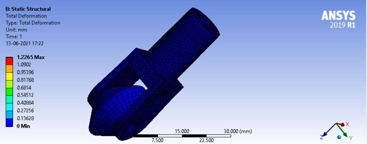
Alongwiththethermalstresses,stressesduetopressureandloadingconditionshavetobeconsidered.So,the pressureof 1.0053*10-4 MPaisappliedatthetwoupperfacesoftheprobe.Theworkpieceisfixedastheworkpieceisclampedduring theweldingoperatingcondition.
Results:
Figure 17 below shows the Total deformation of the probe is negligible concerning the dimension considered. But the maximumdeformationisobservedtobe1.2265mm.
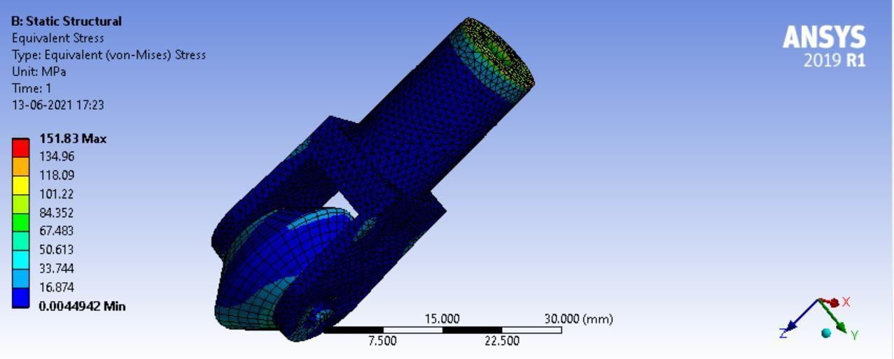
Figure18belowshowstheequivalentstressintheprobe,themaximumstressobservedistheholdingsectionoftheprobe androllingcontactbetweentheprobeandtipandweldjoint.Duetotheconcentrationoftheforceontherollingcontact betweentherollerandworkpieceandalsoduetotheloaddistributionattheholdingsection,maximumstressisinduced atthesetwosections.Themaximumstressis151.83Mpaandtheminimumstressis16.874MPa.
3.4.6 Factor of safety
Thefactorofsafetyisasignificantparameterasitexpresseshowstrongssystemisandhowstrongthesystemneedsto be.Thefactorofsafetyistheratioofyieldstresstoworkingstress.Ifthefactorofsafetyisgreaterthan1,thenthe design isconsideredtobesafe.

From above Figure 19, It is observed that the safety factor is less at the holding faces of the probe which is less than 1, whichisconsideredunsafeforuse.Atalltheotherpointsoftheprobe,thesafetyfactorisgreaterthan1.So,alltheother pointsoftheprobearesafe.
3.4.7 Life of the Spherical probe

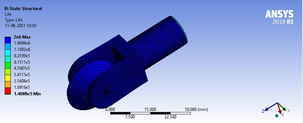
By doing fatigue analysis, the life of the spherical probe was found to be 15 years, if the probe worked for 2 hours in 1 cycle.Figure20showsthestudydonetoestimatethelifeoftheprobe.
The Overall Result of the study done on roller probe:

From the data obtained from the Steady-state thermal analysis, it is observed that thermal stresses are induced at the rolling contact between the roller and workpiece. Also from data acquired from static structural analysis, it can be observedthattheFactorofsafetyattheholdingsectionoftheprobeislessthan1.whichconsequentlymakesitanunsafe design. To term a design as safe design the factor of safety of the component should be more than 1. To track the weld joint,thestrengthoftheholdingjointoftheprobeneedstobemaximum,fortheprobetotrackaccurately.Theprobeacts as a component that senses and any deformation caused by the design failure in the holding section of the probe might alterthedatatransferredtothepositionsensors.Tomaintainthestiffnessandtrackingaccuracyofthewholesystem,the designhastobesafe. Toresolvethisproblem,anewprobewasdesigned,analysedandtested.Therollingcontactofthe probewasreplacedbythepointofcontactofthesphericalprobe.Todeterminethesafetyfactor,ananalysiswasdoneon ANSYSsoftware.
3.5 Analysis of spherical probe
Theresultsobtainedaftertheanalysisoftherollerprobewerenotappropriate.Requiredresultswerenotobtainedeven aftermanymodificationsinthedesigntominimizethestressesandtoincreasethefactorofsafety.Toresolvetheseissues, anewprobewasdesignedandverifiedbyindustryprofessionalsunderweldingconditions.Therollerprobewasreplaced by the spherical probe keeping the joint parameters the same. Analysis of the spherical probe was performed under the welding conditions and the results were satisfactory. The data from the design and analysis of the probe are mentioned below.
3.5.1 Design parameters
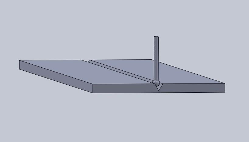
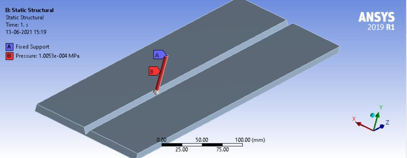
The 3D model isgenerated inthe Solidworkssoftware. AVgroove ofan expectable size of8mm depth with a 30-degree angle is considered and a probe of 8mm diameter is designed. Figure 21 shows the CAD Model of the V-groove and the sensingprobe.
3.5.2 Material selection
Afterexaminingthehardness,thermalcoefficientofLinearexpansionandcorrosionresistance,SS431wasselected.SS431 has its application in the manufacturing of bolts, shafts, pumps, propeller shafts and in laboratory appliances.The 400 series of stainless steels have higher carbon content, giving it a martensitic crystalline structure. This provides high strength and high wear resistance.ThechemicalandphysicalpropertiesofSS431areasfollows:

Table 3: Mechanical Composition of SS431
3.5.3 Meshing
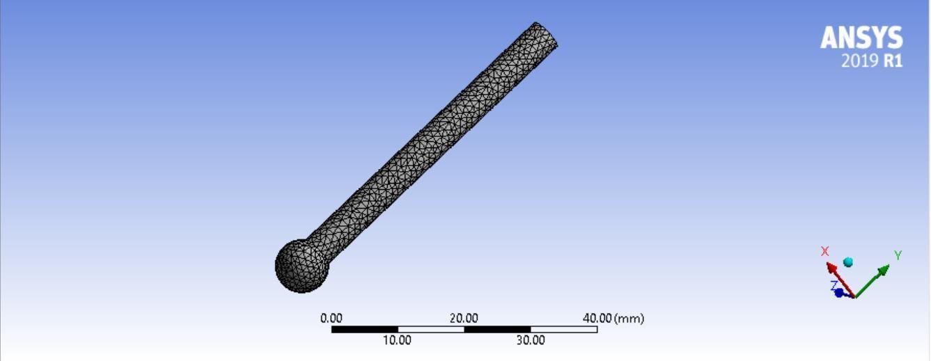
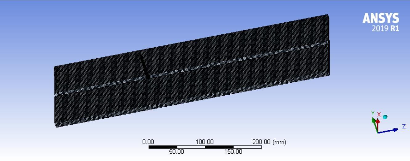
After the geometry is generated, the 3D model of the probe meshes with an element size of 1mm. And the workpiece meshedwiththeelementsizeof2mm.Finemeshisgiventoenhancetheaccuracy.
3.5.4 Steady state thermal analysis

During the welding conditions, thermal stresses are induced in the probe due to the contact between the probe and the workpiece and also due to the heat of the welding torch. These thermal stresses may cause the probe to deform, which might affect the sensing mechanism of the system. Data obtained from a deformed probe will not be accurate, hence it ll affectstheefficiencyofthewholesystem.Steady-statethermalanalysisshowsthedistributionofstressonthecomponent andthedesigncanbemodifiedlater.
Temperature Constraints:
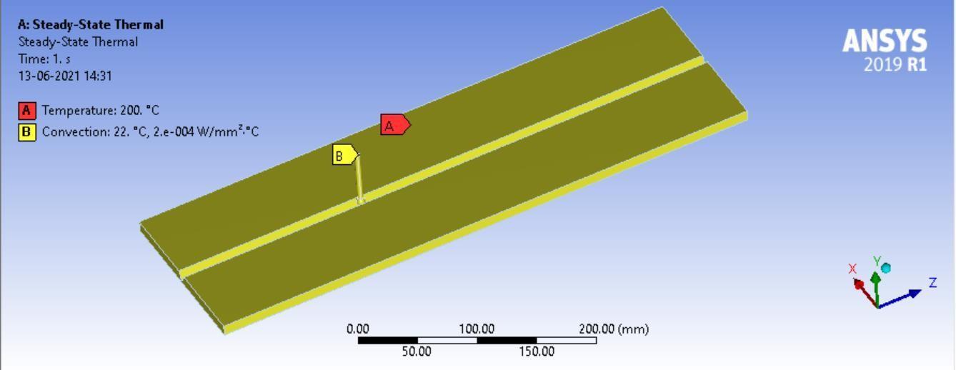
Afterdiscussingthepracticaloperatingparameterswiththeindustryfromthedomainofweldingautomation (Figure24), theinitialtemperatureoftheworkpieceis200Candtheconventionaltemperatureontheprobeis 22C.Thefigurebelow showstheinitialtemperatureconstraintsgiventotheprobeandworkpiece
Results:
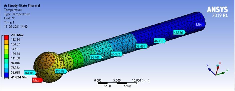
ThetemperaturedistributionisshowninFigure25.Themaximumtemperatureisatthetwopointsoftheprobewhichare in direct contact with the side faces of the V joint. The two faces of theV joint are under the temperature and when they comeincontactwiththepointsoftheprobetip,Heattransfer occursthereforethosepointsontheprobeareshownasa high-Temperature zone. The other points of the probe are away from the joints so they experience less temperature as comparedtothetipoftheprobe.S,theseareasareshownindifferentshadesofblue.Thetemperaturegoeson decreasing aswemoveawayfromtheprobetipandisminimumattheedgeoftheship.
3.5.5 Static Structural analysis of the Spherical probe tip:
TheSensingProbegoesthroughDisplacement,Stresses,StrainsandForcescaused byloadssoitisnecessarytoperform Static structural analysis. The Probe is under small pressure which keeps it in contact with the V joint, so to find the stresses induced in the probe after the pressure is applied along with the Thermal Stresses, Static Structural Analysis is performed. The Static Structural analysis using the Fatiguetool alsohelps in predicting theFactor of Safety and Fatigue Lifeoftheprobe.

Loads and Constraints:
Alongwiththe thermal stresses,the stresses due topressure also has tobeconsidered. So,the pressureof 1.0053*10-4 MPa is applied at the two upper faces of the probe. And the results are manipulated by Ansys solver. The Workpiece is fixedastheworkpieceisclampedduringtheweldingoperation.RefertoFigure26.

Results:
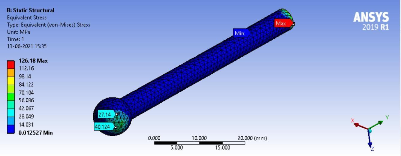
AboveFigure27showstheequivalentstressoftheprobe.Thestressdistributionismoreatthetwopointsoftheprobetip asthesepointsarecomingincontactwiththeVjoint.Someamountofstress is also observed at the top holding face of the probe because of the pressure acting on the faces oftheprobe.TheMaximumstressis126.18MPaandtheminimum is0.0125MPa.
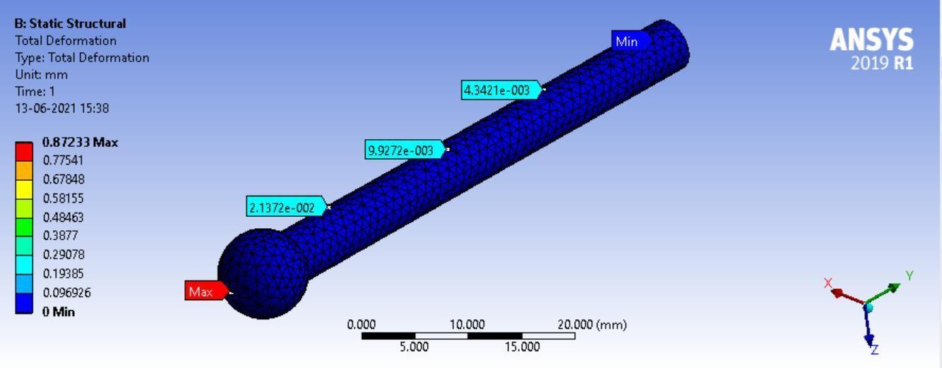
Figure 28 shows the Total deformation of the probe. Deformation is negligible compared tothe dimension of the probe. Maximumdeformationoccursatthecircularprobetipi.e.,0.8723mm andMinimumattheedgeoftheprobei.e.,0.09692 mm.
3.5.6 Factor of Safety
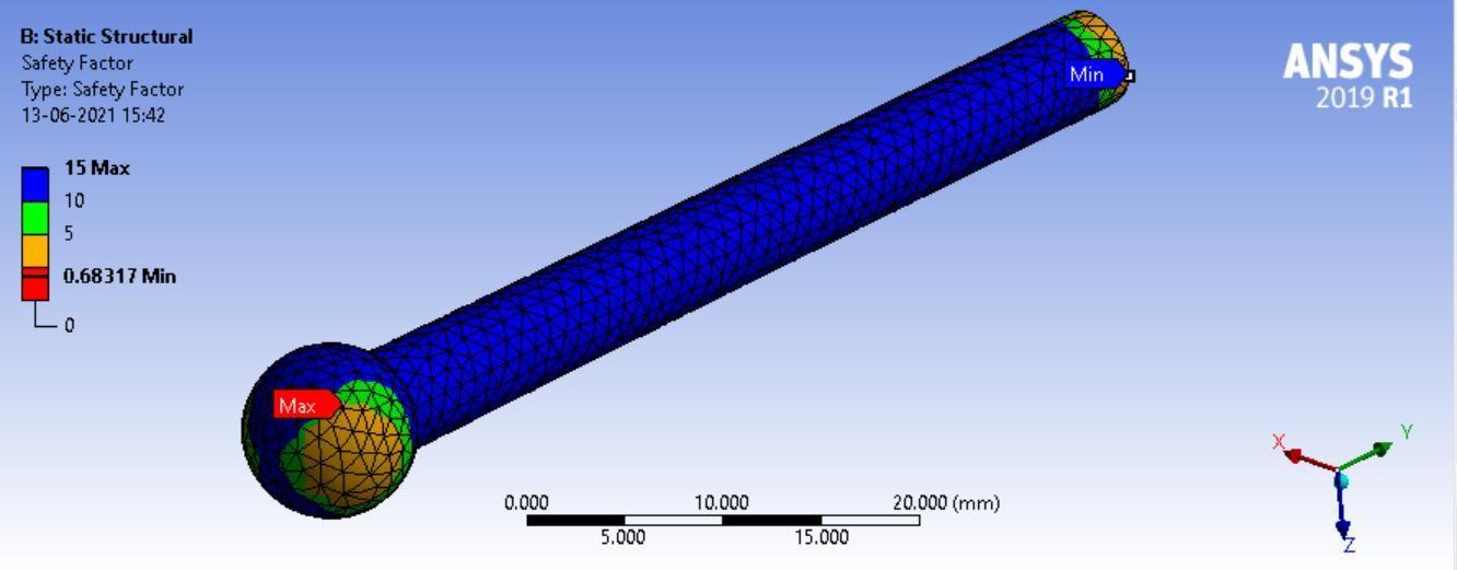
Afactorofsafetyisasignificantparameterasitexpresseshowstrongthesystemisandhowstrongthesystemneedsto be.Thefactorofsafetyistheratioofyieldstresstoworkingstress.Ifthefactorofsafetyisgreaterthan1,thenthedesign isconsideredtobesafe.

Above Figure 29 shows the Safety Factor of the probe. The Safety factor is less at the interface of the probe tip and the holding edge of the probe, but the overall designis safe. A factor of safety obtained is nearly equal to 1, so the design is consideredassafe.
3.5.7 Life of the Spherical probe
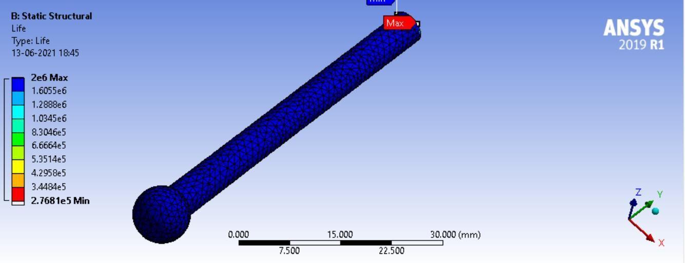
By doing fatigue analysis, the life of the spherical probe was found to be 30 years, if the probe worked for 2 hours in 1 cycle.ThestudyresultsareshownbelowinFigure30.
LifeofthesphericalprobeTip
The overall result of the study done on the spherical:
Fromthedataobtainedfromtheoverallanalysis,itisobservedthatthedistributionofthermalstressismoreatthetipof theprobeasittouchesthejointoftheworkpiece.Thecontactsectionoftheprobegoesthroughasmallamountofthermal deformation.Stressesduetotheloadactingontheprobearealsoconcentratedatthecontactsoftheprobeandworkpiece. Afactorofsafetywasfoundtobemorethan1,eveninthesectionsofhigh-stressconcentrations.Hence,theoveralldesign issafe.Theresultsobtainedfromfatigueanalysis,thelifeoftheprobewasobservedtobe30yearswhichisdoubleofthe rollerprobedesigned
3 CONCLUSIONS
Optical seam tracking is a popular method used in industry for tracking the weld joint, however, it comes with the following disadvantages. Firstly, The depth of the V-Joint of the shiny metal like aluminium cannot be determined. Also, Outsidelightinterferencecanaltertheperformanceaswellastheresultsobtained.Secondly,Thecostofthelasersystem isveryhigh,makingitanunfavourableoptionforsmall-scaleindustries. Anotherseam-trackingtechniqueusingatactile sensor has been designed to eliminate these problems. The sensing operation is done by the probe, which reduces the overallcostofthesystem.Inadditiontothis,nofiltersystemisrequiredtoreducethenoiseintheoutputdata.
The tactile seam tracking system is designed by analyzing the component in the welding condition by using simulation software.Initially,Asensingprobewitharollerwasusedinthissystemanditwaslaterreplacedbyasphericalprobe.The stresses induced at the interface of the probe and the weld joint were more in the roller probe tip as compared to the sphericaltip.Itcanbeconcludedthatthesphericaltipwillnot getdeformedandcanbeusedforalongertime.Bydoing fatigueanalysis,thelifeofthesphericalprobe wasfoundtobe30yearsandthatoftherollingprobewasfoundtobe15 years,whichshowsthatthelifeofthesphericalprobeismorethantherollingprobe,ifboththeprobeworkfor2hoursin 1cycle.Asthedeformationduetoloadandtemperaturearelessinthesphericalprobe,thedatasenttothecontrollerwill beaccurate.Theoverallresultsprovethatusingasphericalprobewillbeanefficient,long-lastingandcost-effectiveoption fortheindustry.
REFERENCES
[1] Wolffenbuttel,R.F., & Regtien, P. P. L.(1986, October). Integrated capacitive tactileimaging sensor. In Proc.16thInt. Symp.IndustrialRobots,Brussels(pp.633-641).https://doi.org/10.1016/0250-6874(89)80068-X
[2] Pires, J. Norberto & Loureiro, A. & Godinho, T. & Ferreira, P. & Fernando, B. & Morgado, Joel. (2003). Welding robots. Robotics & Automation Magazine, IEEE. 10. 45 - 55. 10.1109/MRA.2003.1213616.
https://www.researchgate.net/publication/3344650_Welding_robots

[3]Chen,S.B.(2011).ResearchEvolutiononIntelligentizedTechnologiesforRoboticWeldingatSJTU.In:Tarn, TJ.,Chen, SB.,Fang,G.(eds)RoboticWelding,IntelligenceandAutomation.LectureNotesinElectricalEngineering,vol88.Springer, Berlin,Heidelberg.https://doi.org/10.1007/978-3-642-19959-2_1
[4]DeXu, MinTan, XiaoguangZhaoand ZhiguoTu.SeamTrackingandVisualControlforRoboticArcWeldingBasedon Structured Light Stereovision. International Journal of Automation and Computing, vol. 1, no. 1, pp. 63-75, 2004. https://doi.org/10.1007/s11633-004-0063-0
[5] (1996). A robust visual seam tracking system for robotic arc welding. Mechatronics, 6(2), 141-163. https://doi.org/10.1016/0957-4158(95)00069-0
[6] Gao,X.,&Na,S.(2005).DetectionofweldpositionandseamtrackingbasedonKalmanfilteringofweldpoolimages. JournalofManufacturingSystems,24(1),1-12.https://doi.org/10.1016/S0278-6125(06)00002-1
[7] Gu, W.P., Xiong, Z.Y. & Wan, W. Autonomous seam acquisition and tracking system for multi-pass welding based on visionsensor.IntJAdvManufTechnol 69,451–460(2013).https://doi.org/10.1007/s00170-013-5034-6
[8] Kim,C.,Choi,T.,Suh,J.,Park,K.,Lee,J.,Kang,H.,Lee,M.,&Kim,S.(2008).SensorGuidedLaserWeldingRobotSystem. IFACProceedingsVolumes,41(2),4324-4329.https://doi.org/10.3182/20080706-5-KR-1001.00728
[9] Xu,D.,Fang,Z.,Chen,H.etal.CompactvisualcontrolsystemforaligningandtrackingnarrowbuttseamswithCO2 gasshieldedarcwelding.IntJAdvManufTechnol 62,1157–1167(2012).https://doi.org/10.1007/s00170-011-3873-6
[10] Shen, H., Lin, T., Chen, S. et al. Real-Time Seam Tracking Technology of Welding Robot with Visual Sensing. J Intell Robot Syst 59,283–298(2010).https://doi.org/10.1007/s10846-010-9403-1

[11] Carolina Pimenta Mota, Marcus Vinícius Ribeiro Machado, Roberto Mendes Finzi Neto & Louriel Oliveira Vilarinho(2015)Near-infraredvisionsystemformonitoringarcweldingprocesses,WeldingInternational,29:3,187-196. https://doi.org/10.1080/09507116.2014.932975
[12] Zou, Y., Wei, X., & Chen, J. (2020). Conditional generative adversarial network-based training image inpainting for laser vision seam tracking. Optics and Lasers in Engineering, 134, 106140. https://doi.org/10.1016/j.optlaseng.2020.106140
[13] Y.Zou,Y.Li,L.JiangandL.Xue,"Weldpoolimageprocessingalgorithmforseamtrackingofweldingrobot,"20116th IEEE Conference on Industrial Electronics and Applications, Beijing, China, 2011, pp. 161-165, doi: 10.1109/ICIEA.2011.5975571.
[14] Neto,P.,Mendes,N.,Araújo,R.,NorbertoPires,J andPauloMoreira,A.(2012),"High‐levelrobotprogrammingbased on CAD: dealing with unpredictable environments",Industrial Robot, Vol. 39 No. 3, pp. 294303.https://doi.org/10.1108/01439911211217125
[15] ZhangG,ZhangY,TuoS,HouZ,YangW,XuZ,WuY,YuanH,ShinK.ANovelSeamTrackingTechniquewithaFourStep Method and Experimental Investigation of Robotic Welding Oriented to Complex Welding Seam. Sensors. 2021; 21(9):3067.https://doi.org/10.3390/s21093067
[16] Ben-Ari, M., Mondada, F. (2018). Sensors. In: Elements of Robotics. Springer, Cham. https://doi.org/10.1007/978-3319-62533-1_2
[17]Rout,A.,Deepak,B.B.V.L.,&Biswal,B.B.(2019).Advancesin weldseamtrackingtechniquesforroboticwelding:A review.roboticsandcomputer-integratedmanufacturing,56,12-37.https://doi.org/10.1016/j.rcim.2018.08.003
[18]Zou,Y.,&Chen,T.(2018).Laservisionseamtrackingsystembasedonimageprocessingandcontinuousconvolution operatortracker.OpticsandLasersinEngineering.https://isiarticles.com/bundles/Article/pre/pdf/152342.pdf
[19]www.kunlintech.com
[20]https://metrology.news/ur-certified-optical-laser-seam-tracking-welding-sensors/

