
DEVELOPMENT OF A WHEEL HUB BY TOPOLOGICAL OPTIMIZATION METHOD APPLIED TO A SAE FORMULA VEHICLE
Carlos Roberto Schwaab 1, Sérgio Junichi Idehara1Abstract - In the automotive industry, the technological advancement of computational hardware and numerical method analyzes are increasingly used for the development of complex geometries and products. These have enabled a reduction in design time and manufacture costs. Following this tendency, this work presents the development of a rear wheel hub for a Formula SAE vehicle using the finite element method (FEM) and its numerical tools to obtain an optimum design. An information benchmark was used to create a baseline geometry in CAD software. This model was modified to reduce its mass by the use of a topological optimization. From the optimized design, the efforts due to the vehicle acceleration, braking,corneringand weighttransferloads were analyzed in the FEM model. The static and dynamic stress suffered by the wheel hub were calculated, as well as its safety factor. The results indicated that the mass reduction was possible about 37% of the original geometryandwithaninfinitelifecycleforfatiguefailure.
Key Words: Wheel hub, finite element method, Formula SAE,optimization,automotiveengineering

1. INTRODUCTION
FormulaSAE(FSAE)startedinBrazilin2004,aspartof a competition from the Society of Automotive Engineers (SAE). The objective was to address the shortage of engineersfocusedonhigh-performancevehiclesinthejob market.Thecompetitionconsistedofthedevelopmentofa vehicle prototype, which must be submitted to static and dynamic tests. Besides, evaluating the vehicle's technical characteristicsanddynamicperformanceonanendurance racing[1]
For vehicle design, the numerical method is essential in ordertoimprovetheperformanceandoptimizationofthe product,sinceitscomponentscanbeimprovedatalower cost compared to an experimental method. In the process of developing an automotive component, the use of finite element method (FEM) is essential, since analytical calculations may not be feasible for complex geometries, as generally found. Therefore, as the finite element method is able to perform the analysis of the vehicle or part of it, the method is widely used in the automotive industry[2]
Topological optimization is also an important tool in the development of components for vehicles. Since one of the main factors that influences the racing performance of a FSAE prototype is the mass of the vehicle, lower weight vehicles are designed in order to shorten the lap time. Whenperformingamassreductioninseveralcomponents oftheprototype,thereisasignificantmassdecreaseinthe vehicle that will significantly alter its dynamic performance. Numerous designers are applying this type of development based on simulation analysis and topological optimization to make new structures with improved results in the product design, as a wheel hub designed by Chu et al [3] using carbon fiber material in order to reduce the weight without loss of mechanical resistance.
The wheel hub is a rotational component and generally a componentthatsupportsfourtypesofdynamicloads.The first is the torque coming from the transmission system, thebrakingtorqueofabrakedisc,thethirdandfourthare the weight transferred from the vehicle during acceleration/ braking and the lateral force generated on the vehicle when cornering, both acting on the wheel hub bearing [4]. The purpose of the hub structure is to transmitandresisttheloadstothewheel/tireassembly.
As it is a component of the wheel assembly, it is considered part of the unsprung mass [5], and has influence on the suspension dynamics. Additionally, lighterthewheelhub,loweristhetransmissibilityofroad excitation to the sprung mass and has better contact conditionsbetweenthetireandthepavement [6].Bothof these situations improve the vehicle performance and safetycharacteristicsrelatedtodynamicstability.
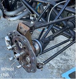
Thus, seeking to improve the dynamic behavior of the vehicle, an optimization of the structure of wheel hub is studies in this work. In Fig -1, the rear wheel assembly of the Formula CEM prototype is illustrated. On a FSAE type vehicle, the mounting that connects the chassis to the wheels via the suspension arms is known as a wheel assembly.Thissetisalsopartofthevehicledriveline.The development of the wheel hub is critical, since there is an influence on drive, brake and cornering dynamics, and overcomingroaduphillanddownhill[7]
Considering this scenario, this study uses concepts of vehicle dynamics and structural design for product
development, using the finite element method and topological optimization for the wheel hub design of a FormulaSAEvehicle.
Tostartthewheelhubmodelling,thereareseveraldesign requirements to be followed, such as driveline shaft diameter, bearing dimensions and wheel fastener pattern [10].Thisinformation was addedasa benchmarkingdata tocreateaninitialmodelofthewheelhub.
1.1 Wheel hub
The wheel hub is a component present in most vehicles, whether passenger, light or heavy commercial vehicles.Itisacomponentmountedonthevehicle'swheel set, and contains the wheel bearing and fasteners for the brake and wheel assembly, in addition to serving as the only attachment point for the wheel [8]. According to Bhanderi et al. [9], the rear wheel hub is in direct contact with four componentsof other vehicle systems:the brake disc, the wheel, the wheel bearing and the axle shaft for rear-wheel drive vehicle. Generally, the hub has two regionsknownaspetals:oneonthewheelattachmentand anotheronthebrakediscattachment[7]
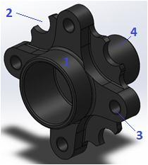
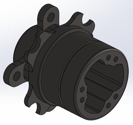
The rear wheel hub of a Formula SAE vehicle, Fig -2, is composedoffourmainsections:
(1) A region where the transmission system is coupled, whenvehiclehasrearorall-wheeldrive;
(2)Brakedisccouplingsectorbymountingbuttons;
(3)Vehiclewheelcouplingsector;
(4)Andapartconnectedbyinterferencetotheinnerrace ofthewheelbearing,thatsupportsthehub.
The most common coupling systems between the vehicle transmission and wheel hub is a constant-velocity (CV) joint(alsonamedashomokineticjoint)oratripodjoint.In Fig -2, the wheel hub used by the Formula CEM team for theyear2021employedtheCVjoint.Thenewdesignwill changeittoatripodjoint.
2. METHODOLOGY
In this section, the steps for the development of the wheel hub are presented. The first step models an initial geometryofthewheelhub,takingintoaccounttheposition requirements and interactions with other vehicle systems The second step is the determination of the loads that act on the component, including those from transmission system, brake, load transfer and lateral acceleration Afterwards, the initial geometry is subjected to a topological optimization considering these loads, in order to remove material from unsolicited areas in the component ThisprocessisbasedonsoftwareSolidWorks. Finally, a static and fatigue failure analysis of the FEM model of the wheel hub is carried out in order to verify whether the component is fit for use, using ANSYS software.
2.1 Baseline geometry
Initially, a conceptual geometry is developed in Computer AidedDesign(CAD)throughtheSolidWorkssoftware.The model is based on a benchmark, carried out through research with other FSAE teams. This geometry must be changeable in order to optimize its mass, reduces stress concentrators, and enable its manufacture according to availableresources.
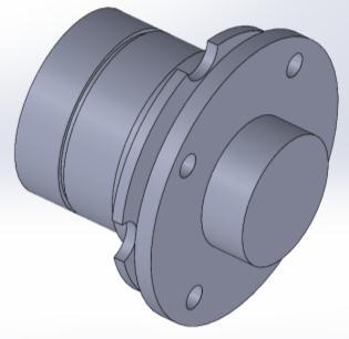
To model the geometry, the following was assumed. Firstly, it uses a tripod joint from the original equipment manufacturer (OEM) component as a joint between the axleshaftandthewheelhub.Boltsmakethecouplingwith the wheel disc in the 4x100 mm spacing pattern. The brake disc is positioned with four buttons, and a ball bearing as the wheel bearing. The resulting model is illustratedinFig-3
2.2 Load calculation: traction and braking
In order to determine the acceleration performance of thevehicle,themaximumtractiveforceofthevehicletires mustbedetermined.Itcanbecalculatedbythecoefficient offrictionbetweenthetireandtheroad,inadditiontothe normalloadontheaxles[11]
Assuming that the power and torque generated by the drivetrain are sufficient, the maximum tractive effort betweenthetireandthegroundisdeterminedbytheroad adhesion coefficient and vehicle parameters [12]. As the Formula CEM has only one drive axle in the vehicle rear, all the power generated by the engine is transmitted only tothesewheels.
According to Wong [11], the tractive effort ( ) of a vehicle with manual transmission and rear wheel drive canbedeterminedbyEquation(1)
Therefore, based in Equation (1), the value of the maximumtractionforceisequalto1,872.87N.
Forthebrakesystem,ofwhichthepurposeistocontrolor stopthevehiclemovement,thefrictiongeneratedbetween the brake discs and the brake pads generates the main braking force. For the analysis in this case of the wheel hub, the forces acting on the rear axle of the vehicle was analyzed.

Additionally, the maximum brake force ( ) that can besustainedincontactbetweenthetireandthegroundis determined from the normal load and the road adhesion coefficient. For the rear axle, it can be determined by Equation(2)[11]
UsingthedatapresentedintheTable-1andEquation(2), the maximum braking force value on the rear axle is 1,082.30N.
2.3 Load calculation: lateral movement
Thehighestvalueoflateralloadswithouttheprototype loses directional stability is 1,710 N according to Santos [13]. The author simulated in ADAMS/Car software for a FSAE vehicle a fish hook maneuver at maximum speed of 100 km/h. The lateral forces in the tire were determined in that work. Then, this value was applied for the calculationsofthelateralefforts.
2.4 Load calculation: vertical load transfer
Where is the friction coefficient of the pavement and the rolling resistance coefficient. For asphalt road, the adoptedvaluesare,respectively,0.85and0.013[11]. is the weight of the vehicle, the distance between the centerofgravity(CG)andthefrontaxle, theheightofthe center of gravity and the vehicle wheelbase. The specificationsofthevehicledataareindicatedintheTable -1
Table -1: Vehicledata.
Thelongitudinaleffectsofaccelerationandbrakingona vehicle generate a load transfer between the front and rear axles. When the vehicle is under the influence of positive acceleration, or under braking or negative acceleration, an inertial force similar to centripetal force develops[14]
According to Milliken and Milliken [14], the longitudinal loadtransfercanbedescribedbyEquation(3).
Where, is the load variation between the vehicle axles, is the longitudinal acceleration of the vehicle (measuredintheCG)and isthegravityacceleration.
Thetotalverticalforceononewheelofrearaxle( )is given by adding or subtracting the weight transfer in the staticweightdistributionasindicatedintheequation(4)
When a vehicle is turning, an inertial force called centripetal force appears, in the opposite way to the lateral acceleration developed in the contact between tire and pavement. The centripetal force is given by the term ,where istheCGlateralacceleration.Assuming that the mass distribution of the vehicle is symmetrical about the lateral axis, the load transfer due to turning movementcanbedescribedbyEquation(5). . (5)
Where,thevehicletrack is denoted by andtheheight of the CG by . The vertical load on one wheel is given by equation(6) (6)
Substituting the values, according to Table -1, into Equations (3), (4), (5) and (6), and assuming a longitudinal acceleration of ±1g and a lateral acceleration of 1.1g, the values of the vertical load on the rear wheel are given in the Table -2 for different vehicledynamicsituations
3. TOPOLOGICAL OPTIMIZATION
SolidWorks software allows, through the Simulation extension,theanalysisofmassreductionofthewheelhub shown in Fig -3. To obtain a rigid structure of the wheel hub,itshouldhaveasmallestpossibledeflectiongiventhe boundary conditions. The way to measure the displacementinordertodeterminethestructurestiffness isbasedonstrainenergy.Thus,carryingoutadesignthat considers the minimum strain energy, a maximum global stiffnessofthecomponentcanbefound[18]
2.5 Material properties
As the wheel hub is subjected to different loads and time-variable characteristics, it may fail due to structural fatigue. For a safer design, minimizing the occurrence of cracks [15], this methodology considers the effects of static and dynamic loads for an infinite fatigue life cycle The material of the wheel hub is an austempered ductile iron (ADI). ADI has higher fatigue strength and wear resistance than the traditional ductile iron [16] The ADI Wöhler diagram is present in Fig -4, considering the ultimate tensile strength ( ) of 1,103.00 MPa and the yield strength of 835.50 MPa. These values are applied in theEngineeringDatasectionoftheANSYSsoftware,asthe propertiesofthematerialusedintheFEMsimulation.
The applied value of a global fatigue coefficient (fatigue strength factor) is 0.63 and obtained based on Norton [17].ThepropertiesoftheADIfordensity,Poisson’sratio and elasticity modulus are, respectively, 7850 kg/m3, 0.3 and200MPa.
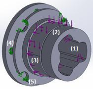
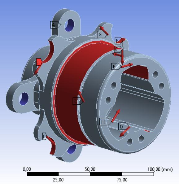
To run the topological optimization, the condition of lateral and positive longitudinal acceleration is considered, which is the major value calculated in Table2.Afterwards,boundaryconditionsaretheforcesfromthe powertrainsysteminthethreeinternalregionsofcontact of the tripod joint (1), the vertical load of sprung mass from the weight transfer (2) and the load from its lateral acceleration(3),bothintheregionofthebearingseat;and thewheel(4)andbrakedisc(5)attachmentsasconstrain. TheseconditionsareillustratedinFig-5
In this case, the objective function is chosen for its minimization of the wheel hub mass without losing the structure integrity. The mass reduction goal was set to 35%.

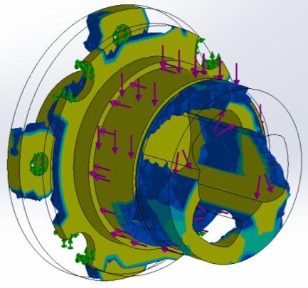
To evaluate the analysis, it is necessary to indicate the regionthatmustbepreservedbythedesignrequirement. Therefore, all areas where loads are applied must be preserved [19]. Also, the optimizer should keep the regions of the shaft shoulder and elastic seating ring. For the functional operation of the tripod joint, the internal facesofthehousingwerepreserved,aswellasaminimum thicknessformanufacturingbycastingprocessof4mm.
Fig -6 shows the regions that may undergo mass reduction. The regions highlighted in yellow are the ones thatshouldbekept,whiletheregionsinbluearetheones that can be removed from the component. Those regions may be eliminated without change the structure stiffness. As the solution of topological optimization gives a nonuniformdesign,anewmodelmustbecreatedbasedon that solution to be manufacturable. The reconstructed wheelhubispresentedinFig-7
Theinitialgeometryofthewheelhubhadamassof2,820 grams, while the final geometry had a mass of 1,764 grams. Therefore, the mass reduction is about 37% comparedwiththeoriginalmodel.
contact with the wheel fasteners the maximum size was 0.5 mm. The final mesh generated for the wheel hub is illustratedinFig-8.
Inthesimulationsforstaticandfatiguefailuresconsidered simultaneous different loading cases. These loads were determined in previous section as the maximum tractive force, maximum braking force and a greatest possible lateral force for the vehicle. The vertical load was applied on the bearing seat considering the major value of the Table -2 (Fig -9). This condition is an unlikely application case,wherealltheloadsareappliedatthesametimeand attheirmaximummagnitude,anditisusedtovalidatethe topologicaloptimizationresults.
As illustrated in Fig -9, the regions of contact of tripod jointreceivethetorqueofthetransmissionsystem,which was decomposed into three tangential forces applied in each section. The four regions in contact with the brake disc buttonsreceived one-fourthofthe maximum braking torque in tangential direction. The wheel fastener positionswereconsideredtobeconstraintpoints.
4. FINITE ELEMENT MODEL
The finite element method consists of a numerical method to solve mathematical problems used in the engineering, and can be applied in problems of structural analysis,heattransfer,andfluidflow,amongothersissues. The FEM presents an approximate numerical solution to the mathematical problem in question, thus representing thephysicalproblemwithacertainprecision[2].FEMisa usualtoolappliedbyengineerstomodelandsimulatereal conditionloadsonthevirtualproduct,asworkedbyYang etal[20]inawheelhubsimulationforquantifytheefforts inimpacttests.
For the model of this study, a quadratic tetrahedral element was used in the FEM model performed in ANSYS software. The wheel hub model is obtained with a maximum element size of 2 mm, while the regions in

5. RESULTS
5.1
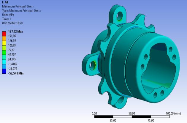
Fig-10presentsthemaximumprincipalstressfromthe static condition of the FEM model. The failure criteria for the selected material has a brittle type fracture [21], thus theprincipalstressisemployedfortheanalysisandsafety coefficientcalculation.
The critical regions are found in stress concentration locations;inthiscaseitisnearbythefastenerholes.These regions present a discontinuity in the flow of forces, and due to the mechanical characteristics of brittle materials, small radii and notches may start fractures in the structure,beinganimportantpointforstructuralintegrity verification. For the wheel hub deflection, Fig -11, the maximum value is about 13.3 µm. This magnitude can be considered acceptable, as it is applied in a region where the deflection would not interfere with the component's operation. Since, it is located in the external region of the housingontheothersideofthetripodjointcontact.
Basedontheregionwiththecriticalstressvalue,thestatic safety factor of the component is equal to 3.9. This is considered relatively high for this application, since the ideal design is to achieve a lower safety factor in order to reduce the mass of the product. However, since the application of wheel hub considers dynamic loads, it is expected that its fatigue safety coefficient is lower, as calculatedinnextsection.

5.2 Fatigue condition
Due to the difficulty of acquiring precise data of the time-dependent load acting on the component, a hypothesis of an input excitation varying between 30% and 100% of its maximum value is adopted. The fatigue model of Goodman was employed in this study for the safetycoefficientcalculation.
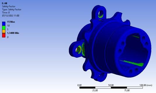
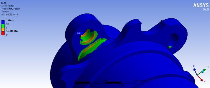
Fig -12 shows the safety factor determined based on the WöhlerdiagramofFig-4.Thatcriticalregionalsoappears inthewheelboltsfixation.Thehighstressisaresultofthe combined effect of loads, like bending, shear and axial stress provoked by the loads of the tripod joint, brake buttons and vertical weight transfer load in the stress concentration location, Fig -13. These points are possible failure regions, where a surface crack may be generated [22].
Fig
Therefore,thevaluefoundforthefatiguesafetycoefficient of the new design of the wheel hub is 1.35. This value is determined for an infinite life cycle. The results of the safety coefficient assures that the solution of the topological optimization is adequate to be used in the vehicle.
6. CONCLUSION
The present study developed a model of a rear wheel hub for Formula SAE vehicle. From vehicle dynamic requisites, several load situations were identified, which component may be requested during its operation. It was found that a drive condition in acceleration, simultaneous with turning movement, results in higher vertical load on thewheelbearing.Thisconditionwithdrivetorqueonthe tripodjointwasappliedforthetopologicaloptimizationto designaproductmodelthataimforaminimummass,but keeping its structural stiffness. A new product was obtainedwithamassreductionfrom2,820gramsto1,764 grams, thus guaranteeing a lighter design with lower fabrication costs. I.e., less material would be necessary in the casting process. The results of the failure analyses made by FEM calculations can be considered satisfactory, since a fatigue safety factor of 1.35 was obtained. This level of factor is in accordance with the standard adopted by the team. Thus, the component has an infinite lifespan that ensures the wheel hub may be applied for the future vehicleprototypes.
REFERENCES
[1] SAE International, Formula SAE rules 2022: Formula SAErules2022,2.1ed.,SAEInternational,2021.
[2] J. Fish, T. Belytschko, A first course in finite elements, JohnWiley&Sons,2007.
[3] D. Chu, W. Bai, Y. He, M. Ye, J. Li, “Research on lightweighttechnologyofnewcarbonfiberwheelhub strutucture”, IOP Conf. Series: Earth and EnvironmentalScience,632,2021,pp.1-8.
[4] K. Karthikeyan, R. Kishore, K. Jeeva, K. Harin, R.S. Kannan, “Topology optimization of an ATV wheel
hub”, Journal of Physics: Conference Series, 2027, 2021,pp.1-8.
[5] V.Gowtham,A.S.Ranganathan,S.Satish,S.J.Alexis,S.S. Kumar, “Fatigue based design and analysis of wheel hub for student formula car by simulation approach”, IOP Conf. Series: Materials Science and Engineering, 149,2016,pp.1-9.
[6] V.Shah,P.Patel,M.Keshav,“Modelingandanalysisof integrated wheel hub”, Journal of Physics: Conference Series,2256,2022,pp.1-9.
[7] J.V. Umesh, Y. Abhishek, “Designing and optimization of wheel assembly of a Formula student car”, International Journal of Current Engineering and Technology,2016,pp.307-320.
[8] B. Mohite, “Stress analysis and optimization of front wheel hub”, International Journal for Research in Applied Science & Engineering Technology, 2018, pp. 378-387.
[9] S. Bhanderi et al, “Design and optimization Formula SAE drivetraincomponents”,International Journal for Research in Applied Science & Engineering Technology,Changa,2022,pp.492-510.
[10] A.Dalvietal,“Design,optimizationandmanufacturing of wheel assembly system of Formula society of automotive engineers (FSAE) car”, International JournalofCurrentEngineeringandTechnology,2020, pp.218-227.
[11] J.Y. Wong, Theory of ground vehicles, 3. ed., Ottawa: JohnWiley&Sons,2001.
[12] T.D. Gillespie, Fundamental of vehicle dynamics, Warrendale:SocietyofAutomotiveEngineers,1992.
[13] R.K.P.Santos,2016,Desenvolvimentodeprodutopara sistema de suspensão de veículo de competição [Product development for competition vehicle suspension system], Bachelor's dissertation, Joinville: FederalUniversityofSantaCatarina.
[14] W.F.Milliken,D.L.Milliken,Racecarvehicledynamics, Society of Automotive Engineers, Warrendale, USA, 1995.
[15] M. Wakid, N.T. Hidayat, W.D. Setiawan, “Wheel-hub and upright development on GE 19 racing cars for international student car competition”, Journal of Physics:ConferenceSeries,1700,2020,pp.1-9.
[16] J. Olawale, K. Oluwasegun, “Austempered Ductile Iron (ADI): a review”, Materials performance and characterization,5(1),2016,pp.289-311.
[17] R.L. Norton, Machine Design: An integrated approach, 4.ed.,NewJersey:PearsonPrenticeHall,2011.
[18] M.P. Bendsoe, Optimization of structural topology, Shape,andMaterial.Berlin:Springer,1995.
[19] P.F. Xu, S.Y. Duan, F. Wang, “Reverse modeling and topological optimization for lightweight design of automobile wheel hubs with hollow ribs”, International Journal of Computational Methods, 17(9),2020,pp.1-12.
[20] L.Yang,H.Yang,H.Tan,P.Hu,X.Cheng,J.Lu,“Impact test simulation and structural optimization of aluminum alloy A356.2 wheel hub”, IOP Conf. Series: JournalofPhysics:Conf.Series,1074,2018,pp.1-7.
[21] M. Kuna, M. Springmann, K. Mädler, P. Hübner, G. Pusch, “Fracture mechanics based design of a railway wheelmadeofaustemperedductileiron”,Engineering FractureMechanics,72,2005,pp.241-253.
[22] T.Shinde,R.Chavan,P.Savadekar,D.Shinde,N.Jagtap, “Failure analysis of a wheel hub of formula student racingcar”, J.Inst.Eng.India Ser. D,102(1),2021,pp. 73-78.