Volvo Penta TD1030ME VE TWD1030ME TWD1031VE TAD1031GE TAD1231GE TWD1231VE TAD1232GE Workshop Manual

Page 80

Fuel system - Design and function

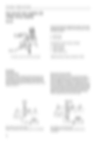
Fuel shut-off valve supplied with voltage during stopping General Fuel shut-off valve for stopping the engine. The valve changes the direction of flow in the fuel system during the stop procedure. A. Solenoid valve B. Valve housing

Connections in valve housing, markings: T. Inlet from fuel tank F. Outlet to feed pump P. Inlet from fuel filter

0 Volt

I.

The diagram shows the fuel flow during operation.

Outlet to injection pump

Tightening torque for pipe connections: 22 Nm.

Function During operation

During the stop procedure

The valve is not connected and the fuel has the normal direction of flow. The fuel pump (3) induces fuel from the tank (5) via the pre-filter (1) after which the fuel is pressed through the fine filters (4) and on to the injection pump (7).

When the key switch is moved to the stop position (“S”) the solenoid valve (2) is activated. The valve therefore changes the direction of the fuel flow to and from the feed pump, whereby an underpressure of 0.3– 0.4 bar is built up in the injection pump’s fuel chamber. This prevents filling of the pump element and the engine stops (the pump element requires overpressure for filling). The overflow valve (6) prevents fuel flowing into the injection pump via the return pipe.

0 Volt

12/24 Volt

Flow diagram, fuel shut-off valve Engine in operation (the solenoid valve is not activated)

Flow diagram, fuel shut-off valve The stop function is activated (the solenoid valve is connected)

78

Turn static files into dynamic content formats.

Create a flipbook

Articles inside

Troubleshooting

1min
pages 160-161, 163

Electricalsystem

2min
pages 148-149

Cooling system - Service Procedures

5min
pages 144-147

Cooling system - Service Procedures

2min
pages 142-143

Cooling system - Service Procedures

3min
pages 140-141

Cooling system - Service Procedures

1min
pages 138-139

Cooling system

1min
pages 128-129

Schwitzer turbocharger

8min
pages 121-127

Intake and exhaust systems - Service procedures

3min
pages 118-120

Service procedures

3min
pages 111-114

Intake and exhaust systems

1min
pages 109-110

Fuel system - Service procedures

1min
pages 106-107

Fuel system - Service procedures

1min
pages 104-105

Fuel system - Service procedures

2min
pages 102-103

Fuel system - Service procedures

2min
pages 100-101

Fuel system - Service procedures

3min
pages 98-99

Fuel system - Service procedures

6min
pages 84-91

Service procedures

1min
pages 82-83

Fuel system - Design and function

1min
pages 80-81

Fuel system

3min
pages 74-79

Oil cooler, leakage test

1min
page 73

Lubricating system - Service procedures

1min
pages 68-69

Lubricating system Design and function

1min
pages 64-65

Engine body - Service procedures

1min
pages 58-59

Engine body - Service procedures

2min
pages 54-55

Engine body - Service procedures

3min
pages 50-53

Engine body - Service procedures

4min
pages 44-49

Valves, adjustment

11min
pages 35-43

Engine body - Service procedures

2min
pages 32-34

Engine body - Service procedures

3min
pages 28-31

Engine body - Service procedures

1min
pages 26-27

Engine body - Service procedures

2min
pages 24-25

Engine body Design

2min
pages 18-21

Repair instructions

6min
pages 9-12

General information

2min
page 8

Safety Precautions

6min
pages 5-7
Issuu converts static files into: digital portfolios, online yearbooks, online catalogs, digital photo albums and more. Sign up and create your flipbook.