EVC-C
Installation procedure, engine room
PCU, installation
Fuel and fresh water level senders
PCU label Green
Pink
X2:DATALINK
X3:ENGINE
X2 Green
Data link – EVC bus cable
X3 Pink
Engine and transmission
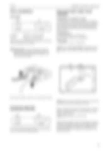
There is a label on the PCU showing the connectors with marking and color coding. IMPORTANT! It is very important to reduce stress from the cables to the connectors. It is recommended that all cables are fixed to the PCU with strain reliefs.
Installation of sender in tank The Volvo Penta fuel and fresh water level senders are suitable for a max. tank depth (H max) of 600 mm (23"). If the tank is deeper, use another sender but note that this sender must have the following resistance scales: Fuel (two types). 3 –180 ohms, 3 ohms = empty tank. 240 –30 ohms, 240 ohms = empty tank Fresh water 3 –180 ohms, 3 ohms = empty tank.. NOTE! Type of fuel level sender is identified by the EVC system when setting “FUEL TANK SET EMPTY”.
Mount strain reliefs as shown in the illustration above. NOTE! Never use the fuel level sender as a fresh water sender. Corrosion problems can occur.
Connect the engine and transmission to the PCU Green
X2:DATALINK
Pink
X3:ENGINE
Connect the cable from the engine, marked CONN X3, to connector X3:ENGINE (pink).
Make a hole for the sender in the fluid tank, diameter 60 mm. Locate the hole so that the float can move freely inside the tank. NOTE! Clean all burrs out of the tank. Adjust sensor length (L=H/2) on the basis of the min. and max. fluid levels. Then do not to forget to extend the sensor length by the gap (A). The gap (A) between the tank and the maximum level must not be less than 40 mm.
43


