8 minute read
Installation procedure, helm

from Volvo Penta D4, D6, D9, D12, D16 Electronic Vessel Control Installation Manual_51339553 PDF DOWNLOAD

Y-connector, location
The Y-connnector is used to form a branch in the EVC standard bus cable when there are several helm stations (HCUs) in the system. Also please refer to the Building a network, requirements chapter.
Key switch and relay for external accessories
IMPORTANT! There must always be one key switch to operate each engine. The key switch shall be connected to the main helm station. On additional helm stations start/stop panels should be used.
IMPORTANT! The Y-connector must always be connected directly to the PCU (X2) or the HCU (X2) without using any extension cables.
Locate a dry, suitable place for the switch and make a hole according to the drawing.
The switch fits to 2 mm (0,08”) panel. If the switch is installed in a thicker panel the switch housing can be trimmed by up to 10 mm (0,4”), 1 mm (0,04”) between each flute.
Connection to the HCU
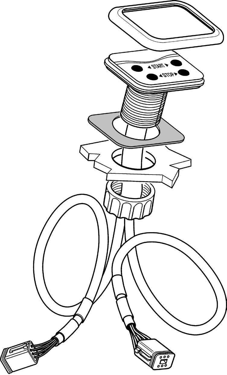
Start/stop panel
Use templates enclosed in the mounting kits. Please refer to the Templates for controls and panels chapter.
NOTE! There are start/stop panels suitable for single and twin installations.
IMPORTANT! For twin installations, it is essential to distinguish between the Red and the Green connections. Red is for port engine and Green is for starboard engine.
The port engine is the master engine.
Flush-mounted panel
Single engine panel is shown.
The key switch is connected to the HCU, X4:KEY connection (gray) togheter with the relay socket for external accessories.
IMPORTANT!
Make a hole for the button panel using the template enclosed with the installation kits. Also refer to the Templates for controls and panels chapter.
The insert depth is 4 mm (0.16") including gasket. Separate the outher part of the gasket (1) from the inner part. Remove the protective paper and fit the gasket (2) in the panel recess.
Install the panel as illustrated in the figure.
Never cut or modifiy the Volvo Penta EVC cable harnesses. For extra power supply use the Volvo Penta relay for accessories.
Refer to the Relay for external accessories section.
NOTE! It is important that the self adhesive gasket is fitted properly in the panel recess.
Frame-mounted panel
Connection to the HCU
Single engine panel
Make a hole for the button panel. The hole must be of diameter 52 mm (2.05").
Separate the inner part of the gasket (2) from the outher part. Remove the protective paper and fit the gasket (2) on the underside of the panel. Install the panel as illustrated in the figure and place the frame over the panel.
NOTE! It is important that the self adhesive gasket is fitted properly on the under side of the panel.
Connect the start/stop control panel cable to the connector marked X4:KEY (gray) on the HCU.
EVC control panel
Flush-mounted panel
IMPORTANT!
Frame-mounted panel
Never cut or modifiy the Volvo Penta EVC cable harnesses. For extra power supply use the Volvo Penta relay for accessories.
Refer to the Relay for external accessories section.
Please refer to the Start/stop panel section for assembling instructions.
Use the templates enclosed with the mounting kits. Please refer to the Templates for controls and panels chapter.
Figures show an EVC control panel for twin engine installation.
Connection of the EVC control panel
Single engine panel
Connect the EVC control panel cable to the connector marked AUXILIARY BUS on the instrument cable harness. The instrument cable harness in turn, is connected to X3:AUX (pink) in the HCU.
Twin engine panel
Connect the EVC control panel cable to the connector marked AUXILIARY BUS on the instrument cable harnesses on the HCUs, red colored cable to port and green colored cable to starboard engines.
The instrument cable harnesses in turn, are connected to X3:AUX (pink) in the HCUs.
IMPORTANT! Green cable to starboard HCU and red cable to port HCU.
Powertrim panel
Connection of the EVC control panel and the Powertrim panel
IMPORTANT! In a twin installation the Powertrim panel must be connected to the HCU for the port engine. The port engine is always the master engine in the EVC system.
NOTE! The Powertrim panel controls both port and starboard drive in a twin installation.
NOTE! For Powertrim switch on side mounted controls, please refer to the Controls, electronic section.
Single engine
Connect the EVC control panel cable marked CONN X3 to the Powertrim panel.
The Powertrim panel and instrument cable harness in turn, is connected to in the HCU, X3:AUX (pink).
Twin engine
Connect the red colored cable to the Powertrim panel, port HCU.
The green colored cable is connected to the connector marked AUXILIARY BUS on the instrument cable harnesses on the starboard HCU.
The instrument cable harnesses in turn, are connected to X3:AUX (pink) in the HCUs.
IMPORTANT! Green cable to starboard HCU and red cable to port HCU.
In a twin installation the Powertrim panel must be connected to the cable harness from the port engine HCU.
Relay for external accessories
Relay
12V, 20A (D4/D6/D9)
24V, 20A (D6/D9/D12/D16)
Relay socket
Connection points on relay socket
Power to accessories
Battery supply
Cable harness
The relay controls the power supply to external accessories. The relay position (open or closed) and the power supply depend on the key switch position. The relay is normally open and there is no power when key switch is in the OFF position.
The relay cable and the relay can also be fitted to a secondary helm station with a start/stop control panel. In such an installation the relay is activated by the key switch on the main helm station.
NOTE! All relays in a drive line, and in an active or inactive helm station are operated by the key switch.
Relay diagram
Connection 85 and +86 are wired from the EVC cable harness.
Figure shows the key switch in OFF position and the relay in open position.
Connect power supply for external accessories from the battery to connector 30 on the relay socket.
IMPORTANT! Never supply any external accessories from the EVC system. Always use the relay.
Connect external accessories to pin 87 which will supply power when the key switch is ON.
Cables from battery to relay and from relay to accessories must be dimensioned for the expected maximum current. There must also be a fuse in the circuit between battery and relay, preferably close to the battery.
Maximum current through the relay is 20 Amp.
Maximum output is:
12 V 240 W
24 V 480 W
Connection to the HCU when using a key switch
Connection to the HCU when using a start/stop panel
The relay socket is permanently connected to the cable for the key switch. The key switch cable is connected to the HCU, X4:KEY connection (gray).
The start/stop panel is connected to the HCU, X4: KEY (gray) or to separate relay cable harness (option).
The cable harness is option. The connector on the harness is marked KEY and the harness is connected to the HCU, X4:KEY connection (gray).
Instruments
Choose dry suitable places for the instruments.
NOTE! Max. distance (CC) between instruments without using an extension cable is 220 mm (8.6").
IMPORTANT! Always connect instruments which are common for both engines, such as speedometer, rudder indicator etc. to port HCU
The port engine is the master engine in the EVC system.
Instrument with attaching nut
Instrument with attaching clamp
NOTE! Attaching clamp is used when dash thickness is between 12 mm (0.5") and 25 mm (1.0"). For dash board thickness less than 12 mm (0.5"), please refer to Instrument with attaching nut.
12–25 mm (0.5–1.0")
Dash board hole diameters: mm (2.05")
Make a hole, diameter 85 mm (3.35") or 52 mm (2.05") depending on type of instrument.
Fit the instrument as illustrated in the figure. Install the gasket (1) between the instrument and the dashboard.
Flush-mounted instrument
Dash board hole diameters: 110 mm (4.33") tachometer, speedometer 85 mm (3.35") tachometer, speedometer mm (2.05") all other instruments
NOTE! An attaching nut is used when dash board thickness is up to 12 mm (0.5"). If dash board thickness is greater than 12 mm (0.5"), please refer to Instrument with attaching clamp.
Make a hole, diameter 110 mm (4.33"), 85 mm (3.35") or 52 mm (2.05") depending on the type of instrument.
Fit the instrument according to the figure. Install the gasket (1) between instrument and dashboard.
NOTE! The position of the attaching ring when insert depth exceeds 2.5 mm (0.1").
Dash board hole diameters: 83 mm (3.27") 49 mm (1.93") mm (0.16")
NOTE! Holes diameters should be 105 mm / 83 mm / 49 mm. Insert depth should be 4 mm (0.16").
Make a hole, diameter 105 mm (4.13"), 83 mm (3.27") or 49 mm (1.93") depending on type of instrument.
Place the sealing ring (X-ring) between the dashboard and the instrument.
Fit the instrument.
Connection of EVC System Tachometer and other instruments
Multilink/tachometer/ synchronization cable, 6-pin
To other instruments
EVC system tachometer
Protection plug
Multilink/tachometer/ synchronization cable
X5 MULTILINK
3-pin instrument cable (incl. in the tachometer kit)
Max. 220 mm (8.6") (all instruments)
Multilink/tachometer/ synchronization cable, 6-pin
MULTILINK BREAKOUT
MULTILINK
CONN X5 Yellow
Extension cable, 3-pin 1.0 m (3 ft), 3.0 m (10 ft)
Connect the other instruments to the 3-pin EasyLink connector in the tachometer.
Protection plug
Connections to:
- Multilink accessories
CONN X5 Yellow
Green Yellow Pink Gray Blue X7:CONTROLS X8:NOT
Connect the EVC System Tachometer to the HCU connection X5 (yellow). Connect directly to X5 using a multilink/synchronization cable.
Allternatively use a Y-split multilink cable and the MULTILINK BREAKOUT connection. See figure.
Connection tachometer
IMPORTANT! Always plug the open end of the instrument cable to prevent corrosion. Use the plug attached to the cable harness.
X5:MULTILINK X2:DATALINK X3:AUX X4:KEY Installation procedure, helm EVC-C
IMPORTANT! Do not install an Y-split cable without having the MULTILINK BREAKOUT connected.
Instrument, panels and auxiliary cable, 6-pin (option)

Instruments
EVC control panel
Buzzer
GAUGES
The instrument cable is connected to the HCU X3: AUX connector (pink).
BUZZER
This cable is optional. It is used when an EVC system display is installed and an additional buzzer is required.
HCU secondary helm station
Buzzer
Tachometer (early type)
Instruments
GAUGES
BUZZER
AUXILIARY BUS
EVC control panel EVC system display HCU
The cable can also be used for an additional buzzer when the EVC system includes an EVC system tachometer. The instrument serial bus can also be used.
Instrument cable
Multisensor
IMPORTANT! In a twin installation, when using one combined EVC system display, the display must be configured as a “TWIN” before auto configuration is performed.
In a twin installation. when using two EVC system displays, the displays must be configured as “PORT” resp. “STARBOARD” before auto configuration is performed.
Buzzer (option)
Gauges
Mount the buzzer under the dash board in an appropriate place by using one or two stripes.
Connect the buzzer cables to the connectors marked BUZZER in the instrument cable harness.
IMPORTANT! Note the pinarity of the buzzer and buzzer cable: Red/blue to red cable, positive (+) and black to black cable, negative (–).
Auxiliary dimmer unit (ADU)
If the existing installation comprises instruments that are not of the EasyLink type, then an ADU can be installed. This means non-EasyLink instrument can also have the lighting intensity adjusted with the dimmer function.
The ADU can be fitted anywhere along the chain of other EasyLink instruments. See the figure below.
The number of ADUs required depends on how many filament lamps/LEDs there are in the circuit. One ADU can supply 5 x 1.2 W (12 V/24 V) filament lamps or 30 x LEDs, 15 mA (12 V/24 V).
When attaching to the auxilary + supply, an extra fuse of max 5 A must be used. See positioning in figure below
Non-EasyLinkequipment
Non-EasyLinkinstrument
Auxilary Supply 12 V/24 V
Fuse box
R/BL, Fused supply
Non-EasyLinkequipment
SB, 0 V
ADU
EasyLink connection
Terminal block
EVC System Tachometer
EasyLink-instrument R/GR, outR, out +
IMPORTANT! Connect supply via relay for external accessories.
LEDs with dropping resistor (or lamps) connected in parallel
Auxilary Supply 12 V/24 V
Fuse max 5A
R/BL SB
SB = (solid) black R = red R/BL = red/blue R/GR = red/gray
R/GR, Out -
R, Out +
ADU
EVC instrument bus In resp. Out
Synchronizing engines in twin installations
To synchronize the engines the multilink/tachometer/ synchronization cable (A) must be installed between the HCUs for starboard and port engines in a twin installation.
The marking sleeves on the cable are yellow and named MULTILINK.
The multilink/tachometer/ synchronization cable (A) is a part of the multilink chain connected to X5: MULTILINK (yellow) on each HCU. See figure above.
IMPORTANT! There must be a syncronizing cable installed between the HCUs on all helm sations.
IMPORTANT! Do not install an Y-split cable without having the MULTILINK BREAKOUT connected.
NOTE! If the system is equipped with e. g. an EVC display an Y-split cable must be installed between the HCU X5 and the display cable. The syncronizing cable is then connected to the Y-split part, marked MULTILINK.


