
9 minute read
Idling speed calibration (If needed)

from Volvo Penta D4, D6, D9, D12, D16 Electronic Vessel Control Installation Manual_51339553 PDF DOWNLOAD

NOTE! When calibrating idling speed the Full Throttle Forwards position on the lever corresponds to maximum idling speed.
NOTE! D4 and D6 engines only: Idling speed adjusting can only be done when the engine temperature is more than 40°C (104°F). When temperature is below 40°C (104°F) only Warming Up mode is activated.
1. Activate helm station by pushing the ACTIVE STATION BUTTON on the EVC panel.
2. Enter calibration mode.
3. Start the engine.
Settings, general
NOTE! For all setting procedures: Activate helm station by pushing the ACTIVE STATION BUTTON on the EVC panel.
Pop-up in display indicates: IDLE SPEED SET RPM
4. Adjust the idling speed with the control lever. Idling speed can be adjusted to a value between:
D4 engines 700–750 rpm
D6 engines 600–650 rpm
D9 engines 500–750 rpm
D12 engines 500–700 rpm (MP), 500–800 rpm (MH)
D16 engines 550–600 rpm
Confirm rpm by pushing the NEUTRAL BUTTON.
5. Move lever to neutral position and stop the engine.
OEM-mode
Enter OEM-mode
NOTE! Always exit OEM-mode before changing helm station.
Fuel tank settings
1. Activate helm station by pushing the ACTIVE STATION BUTTON.
2. Enter OEM-mode
3. Select and enter SETTINGS from MAIN MENU. Select and enter OEM MODE from SETTINGS.
LED
Single installation
LEDs
Fuel tank volume setting
4. Select and enter FUEL TANK TANK VOLUME.
5. Set the fuel tank volume by turning the NAVIGATION WHEEL to an appropriate value and confirm by pushing.
Empty fuel tank setting
NOTE! The fuel tank must be empty.
Twin installation
1. Enter OEM-mode by pushing the MULTIFUNCTION BUTTON for at least 5 seconds.
2 The red (red/green) LED(s) is flashing and popup screen OEM MODE ACTIVATED is shown for approx. 5 seconds.
In twin installations one of the tachometer display is activated. To change tachometer, push TACHOMETER SELECTION BUTTON.
Exit OEM-mode
3. Exit OEM-mode by pushing the MULTIFUNCTION BUTTON for at least 5 seconds. The red (red/green) LED(s) stops flashing. Pop up screen is shown in display for approx. 5 seconds.
6. Select and enter FUEL TANK SET EMPTY.
7. Confirm empty tank in the PUSH WHEN EMPTY window.
Fuel alarm (if needed)
NOTE! The default level of the fuel alarm is set to 0% of the tank volume, which means that the alarm is off. For the alarm to function, the desired alarm level must be set.
8. Select FUEL ALARM SET LEVEL. Push NAVIGATION WHEEL.
9. Set the level (in %) by turning the NAVIGATION WHEEL clockwise or counter-clockwise to an appropriate value and confirm by pushing the NAVIGATION WHEEL.
Fuel tank calibration
Full tank calibration
NOTE! A FULL TANK CALIBRATION requires that FUEL TANK EMPTY has been set.
When FULL TANK CALIBRATION is selected, the fuel level sender is calibrated in two steps. Empty and full. This only gives a very rough estimation of the fuel level. Therefore all trip data concerning and based on, remaining fuel volume should be recognized as approximated values only.
1. Activate helm station by pushing the ACTIVE STATION BUTTON.
1. Select SETTINGS from MAIN MENU by turning NAVIGATION WHEEL. Push NAVIGATION WHEEL to enter SETTINGS MENU.
2. Select FUEL TANK CALIBRATION and push NAVIGATION WHEEL.
3. Select FULL TANK CALIBRATION by turning NAVIGATION WHEEL. Push NAVIGATION WHEEL to enter FULL TANK CALIBRATION.
4. Fill fuel tank and push NAVIGATION WHEEL. Push BACK BUTTON to return to SETTINGS MENU.
Fuel alarm pop-up
The fuel level alarm pop-up will appear when the fuel level is lower than fuel alarm setpoint. The pop-up shows the percentage of fuel remaining.
Acknowledge fuel alarm by pushing NAVIGATION WHEEL.
Fuel level alarm pop-up will re-appear every 10 minutes until the fuel level in tank is higher than fuel alarm setpoint.
Fuel level signal loss
If the fuel level has been set and the fuel level signal is lost, for instance in the case of sensor malfunction, the fuel level alarm signal loss pop-up will appear.
Fuel multipoint calibration
When FUEL MULTIPOINT CALIBRATION is selected, the fuel level sender is calibrated in five equally divided steps; 20 % full (pos 1), 40 % full (pos 2), 60 % full (pos 3), 80 % full (pos 4), 100 % full (pos 5). NOTE! TO perform multpoint calibration, fuel tank must be less than 20% full. If calibration skips POS 1 and goes directly to POS 2, the fuel tank contains too much fuel and the calibration will not be correct.
1. Activate helm station by pushing the ACTIVE STATION BUTTON.
2. Select SETTINGS from MAIN MENU by turning NAVIGATION WHEEL. Push NAVIGATION WHEEL to enter SETTINGS MENU.
3. Select FUEL TANK CALIBRATION and push NAVIGATION WHEEL.
4. Select FUEL MULTIPOINT CALIBRATION by turning NAVIGATION WHEEL. Push NAVIGATION WHEEL to enter FUEL MULTIPOINT CALIBRATION.
5A. If the number after “POS” in the display is flashing: Fill fuel tank with displayed volume (POS 1) and push NAVIGATION
WHEEL. Add fuel (do not reset the pump) up to displayed volume for each POS until the tank is filled.
6. Push BACK BUTTON to return to SETTINGS MENU.
5B. If the number after “POS” is not flashing: Fill fuel tank with displayed volume (POS 1) and push NAVIGATION
WHEEL. Repeat procedure for each POS until the tank is filled.
6. Push BACK BUTTON to return to SETTINGS MENU.
Multisensor calibration
Speed factor
The speed factor for the boat´s paddle wheel speed sensor can be adjusted at a resolution of 1% and is used by the EVC to apply a correction to the output from the speed sensor.
Set speed factor
Set speed factor while driving the boat. Compare displayed speed with speed data from GPS (or other boat) and adjust the speed factor until they correspond.
Adjust the speed factor by turning the NAVIGATION WHEEL.
Once adjustment value is reached, the data is stored by pushing NAVIGATION WHEEL.
Information message
Start attempt with gear engaged
The engine control lever must always be in neutral before starting. If not, this pop-up will be shown.
Approximated trip data
This pop-up will be shown if no multipoint fuel tank calibration is performed.
Retrieving faults
The EVC system is retrieving faults from its nodes.
Monitoring mode (inactive station)
An inactive station can show system information. Push MULTIFUNCTION BUTTON on the inactive station.
It is possible to navigate the menus when in monitoring mode.
Depth alarm (Option)
All depth alarm functions are accessed through this menu.
Requirements
- Activate helm station
- A multisensor needs to be installed
- A signal (approved) must be generated. This is shown in the EVC tachometer display or EVC system display.
DEPTH ALARM, ON/OFF
Depth alarm can be switched ON/OFF.
Set Depth
Adjust the depth alarm value by turning the NAVIGATION WHEEL. The value can be adjusted at a resolution of 0.1 m (1 ft).
Once adjustment value is reached, the data is stored by pushing NAVIGATION WHEEL.
Depth Offset
The depth sounder can be placed somewhere on the hull that gives another depth than the desired depth. You can then add or subtract a distance so that the display shows the depth from, for example, the lowest point on the boat, or from the surface.
Adjust the depth offset value by turning the NAVIGATION WHEEL. The value can be adjusted at a resolution of 0.1 m or 1 ft.
Once adjustment value is reached, the data is stored by pushing NAVIGATION WHEEL.
Depth alarm pop-up
The depth alarm pop-up will appear when the depth is less than the depth alarm setpoint. The pop-up shows the actual depth.
Acknowledge depth alarm by pushing NAVIGATION WHEEL.
The depth alarm pop-up will re-appear every 30 seconds until the depth increases and exceeds the depth alarm setpoint.
Depth alarm signal loss
If the depth alarm is enabled and the depth signal is lost, for instance in the case of sensor malfunction, the depth alarm signal loss pop-up will appear.
EVC system display
Description
Structure of the display functions
Button 1 Engine different(10 fuel informations)
Button 2 Multi (display in several windows)
Volvo Penta display EVC system (EVC system display) is an instrument which displays operating information about the engine and allows you to communicate with the engine’s electrical system.
Operation information is shown on an LCD display. The driver can select the display mode operative on the display with the aid of the five buttons on the front of the instrument.
The four buttons at the furthest left are used to display operating information in different ways. The button at the furthest right is used to adjust the display contrast and to access the so-called configuration menu. Various settings etc. can be done in it. You can also use the configuration menu to reach the display mode SYSTEM INFORMATION (which can also be reached via button 2, please refer to the schedule below). This display mode functions in the same way as the display in the tachometer (EVC system tachometer).
Before the display is used, it may be necessary to modify the way that the display shows operating information, to comply with user requirements. You can see the settings that can be changed in the section about the configuration menu.
IMPORTANT! In a twin installation, when using one combined EVC system display, the display must be configured as a “TWIN” before auto configuration is performed.
In a twin installation. when using two EVC system displays, the displays must be configured as “PORT” resp. “STARBOARD” before auto configuration is performed.
Button 3 Trip Button 4 Graph (display as graphs)
Start image
This is the starting image that is shown on the display for a brief period after starting.
If the unit gives a constant audible warning after starting, the self-test has failed. The unit will still work, but may behave in an unexpected manner.
Symbols for operating information
Engine speed
Coolant temperature
Engine temperature
Fuel pump pressure
Oil pressure
Coolant pressure
Speed
Fuel consumption/time

Turbocharge pressure (current)
Induction air temperature
Exhaust temperature
Voltage
Oil pressure, drive
Oil temperature, drive
Fuel level
Differential pressure, oil filter
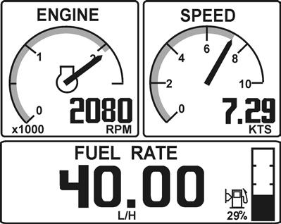
Display after starting screen
Display mode ENGINE (button 1) is always shown after the starting screen when the display is first started up (more information about this display mode can be found below in the instructions). Once the display has been used, it will always show the display mode when it starts up, that was selected when the display was last switched off.
Connection fault
If the display does not register transfer of operating information from the electrical system, the pop-up window will flash CONNECTION LOST. When operating information has been registered/reset, the pop-up window disappears.
Configuration menu structure
System Information
Settings
Read more about this display mode on the next page
Language (8 available) Click sound ON, OFF
Engine PORT, STARBOARD TWIN, SINGLE
Engine series D1/D2, >D2 Settings GLOBAL, LOCAL
Display
Units
Configuration menu (button 5) (Depressed for longer than 3 s)
The configuration menu is used to:
- access the display mode SYSTEM INFORMATION
- do various settings for the display
- reach information and functions for servicing the display
Please refer to the configuration menu structure below and read the following section, which explains each section in the menu.
NOTE! The port engine or both engines must have the ignition switched on when display settings are changed.
System
Demo Com Viewer Prog. tx About
Engine [2500 rpm: 9000 r/min] in stages of 500 rpm
Speed On, off
Speed 10 KNOT: 100 KNOT] in stages of 10 (in appropriate units)
Graph interval 2MIN, 10MIN, 30MIN, 60MIN, 2 H, 4 H, 8 H
Speed Knots, mph, km/hr
Distance NM, Miles, km
Oil pressure kPa, psi
Turbo pressure kPa, psi
Fuel consumption* Liter/hr, Gal(US)/hr, IGal/hr
Temperature degrees C, degrees F
Volume Liter, Gal(US), Imperial Gallons
Depth (std distance) m, ft
Menu SYSTEM is for service technicians
The UNITS menu is only available if LOCAL has been selected in the menu SETTINGS
* Requires trip computer software
Display mode System Information
SYSTEM INFORMATION is a display mode that functions in the same way as the display in the tachometer (EVC system tachometer). You navigate round these functions, using the buttons on the freestanding control panel.
In display mode SYSTEM INFORMATION there are several functions:
- Display of operating information, information messages and alarm (NOTE! The display is adapted to suit the size of the panel in the tachometer).
- Settings for displaying operating information in this display mode.
- All calibrations.
Detailed instructions for the functions in display mode SYSTEM INFORMATION are found in the section about the tachometer in this owner’s manual.
Information message and alarm
The display automatically switches to display mode SYSTEM INFORMATION when the electrical system needs to show information messages or alarms. Instructions about how information messages and alarms should be handled are found in the section about the tachometer and in the section ”In case of emergency” in the operator’s manual.
System
Menu SYSTEM is intended to provide the necessary functions and information for service technicians.
- Demo: Switches between demo mode ON/OFF The unit is in normal operation mode when Demo is OFF.
- Com Viewer: Shows the latest messages received on the communication inputs
- Prog tx: Transfers the contents of the application program in the flash memory to other CANtrak units on the same CANbus link
- About : Shows the following information:
ID no: Display serial number
Eeprom: No. of writes to the EEPROM
Vers: Software version number
Chk: Flash memory checksum
Part no: Volvo’s part number for the software
Source: Shows the source of the received data
Label: Label allocated on the bus. Each unit on the same bus must have its own unique label.


