
6 minute read
Other special equipment

from Volvo Penta D4, D6, D9, D12, D16 Electronic Vessel Control Installation Manual_51339553 PDF DOWNLOAD

The tools below are intended for use in work on the cable harnesses of the engine. The tools are not included in Volvo Penta’s range, they must be ordered from a local AMP or Deutsch dealer. If you experience problems in contacting a dealer, please contact Volvo Penta Quality Action Center for advice.
Deutsch connectors
HDT-48-00 Crimping tool
0411-310-1605 Disassembly tool
16-pin CPC connector, d=1.6 mm (0.063")
725 840-1 Disassembly tool
58 495-1 Crimping tool
JPT connector (42-pin EDC, 2 and 3-pin Bosch etc.)
726 534-1 Disassembly tool 1.6 mm (0.063") pin width
726 519-1 Disassembly tool 2.8 mm (0.11") pin width
825 514-1 Crimping tool
Blades and sockets 3.5 mm (0.14")
725 9380 Disassembly tool
825 582-2 Crimping tool
4.8 mm (0.19") and 6.3 mm (0.25") cable clamps. Tongues and socket terminals
825 514-1 Crimping tool
Deutsch service kit incl. connectors and crimping tool
11 666 200 NOTE! Volvo Part no. only
General view
Major components
Helm Control Unit (HCU), flybridge. Port engine (master)
Helm Control Unit (HCU), flybridge. Starboard engine
Electronic Controls
Helm Control Unit (HCU), main station. Port engine (master) Helm Control Unit (HCU), main station. Starboard engine
Powertrain Control Unit (PCU) Port engine (master)
Helm Control Unit (HCU) Port engine (master) Engine Control Module (ECM)
Powertrain Control Unit (PCU) Starboard engine
Helm Control Unit (HCU) Starboard engine
Reverse gear solenoid valves
EVC system with two inboard engines (twin installation) and three individual helm stations.
Electronic controls
Top mounted controls
Side mounted control
Control, single engine
Control, twin installation
Lever controls for electronic control of engine speed and gear shifting. Available in black or stainless steel housing and for both single and twin installation. The controls are equipped with neutral switches.
Side mounted lever control for electronic control of engine speed and gear shifting. Available for single installation.
Side mounted control with Powertrim switch
Side mounted control. DPH and DPR applications Neutral switch
Side mounted lever control for electronic control of engine speed, gear shifting. The control is available with buttons for Powertrim adjustments and control. Available for single installation. Including cable 2.0 m (6 ft).
Side mounted lever control for electronic control of engine speed, gear shifting and Powertrim. Available for single installation. Including cable 2.0 m (6 ft).
EVC control panels
Powertrim control panel, stern drive DPH/DPR
A control panel is required to start and operate EVC engines.
The panels can be installed with frames or flush on dashboard. The panels are supplied with the necessary connections.
The panel can be installed with a frame or flush on dashboard. The panel is supplied with the necessary connections.
Start/stop control panel, secondary helm station
Start/stop panel, single engine
EVC system display, including cable
The Volvo Penta EVC system display is an on-board instrument for indication of engine operating values, boat speed and other data. The display consists of a self-contained, computerised unit for fixed installation on a dash board. A Liquid Crystal Display (LCD) screen is used for data presentation.
The EVC system display can show information from one or two engines.
If only a display is used (no tachometer) this requires an additional buzzer and an instrument, panels and auxiliary cable.
IMPORTANT! An EVC system display can be connected together with a tachometer. The display can also substitute a tachometer. The EVC system must have either a tachometer or a display.
Key switch, main station
To start and stop the engine from a secondary helm station.
The panel can be mounted with a frame or flush on dashboard. The panels are supplied with all necessary connections.
On the main helm station a key switch to power up the system and start/stop the engine must be installed.
The key switch is available in kits for single and twin installations. A kit for twin installations has two switches which can be operated with the same key.
Instruments
There is a variety of instruments available for the EVC system. The instruments can be ordered with black or white dial face.
The instruments can be mounted with an attaching ring or clamp or flush on dashboard. The instruments are delivered with the necessary wiring for connection to the system.
Some of the most common instrument types are shown below.
Voltage ∅ 52 mm (2.05") (12V/24V)
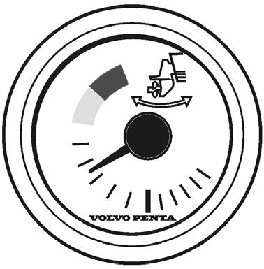
Trim instrument, analog ∅ 52 mm (2.05")
EVC system tachometer. Engine speed incl. buzzer and communication display
∅ 85 mm (3.35") ∅ 110 mm (4.33") (rpm).
The EVC system tachometer has an integrated buzzer and a communication LCD showing alarms, diagnosis data and information about the system. NOTE! The EVC system allows maximum one tachometer per helm station (HCU).
Trim instrument, digital ∅ 52 mm (2.05")
Rudder indicator ∅ 52 mm (2.05")
Speedometer ∅ 85 mm (3.35")

∅ 110 mm (4.33") (knots, mph)
Fuel level ∅ 52 mm (2.05")
Engine oil pressure ∅ 52 mm (2.05") (bar alt. psi)
Coolant temperature ∅ 52 mm (2.05") (°C alt. °F)
Instrument ring kit, chrome/black
The kit contains a front ring, a gasket and an attaching nut or an attaching clamp.
Diameters 52 mm (2.05"), 85 mm (3.35") or 110 mm (4.33") depending on type of instrument.
Multisensor
The multisensor is available in two designs, for transom mounting and for hull mounting. The multisensor submits data about boat speed, water depth and water temperature. Data can be shown in the EVC display. The speed data is also available in an instrument (speedometer).
Gasket for flush mounted instruments
4–20 mA input interface for auxiliary control levers
Input interface to aftermarket control systems that support 4–20 mA. No calibration is needed.
If the instruments should be flush mounted into the instrument panel, a gasket must be fitted to prevent water from entering behind the panel.
Auxiliary dimmer unit (ADU)
4–20 mA output interface for auxiliary control levers
Output interface toaftermarketcontrolsystemsthat .aftermarketcontrolsystemsthat aftermarket control systems that support 4–20 mA. No calibration is needed.
Dimmer for instrument lights in auxilliary instruments and equipment. Instruments not supported by the EVC system (third party instruments). The function is controlled by the multifunction button ( ) on the EVC control panel.
NMEA 0183 interface
Actuator D4/D6, stern drive
Early design EVC-C Major components
Transmits:
Information about boat speed from a GPS or similar, to be presented on an instrument and in the tachometer or the EVC system display. An NMEA interface/ multisensor must be installed to supply this information to the EVC system.
NMEA 2000 interface
Actuator which operate the shift control cable to the stern drive.
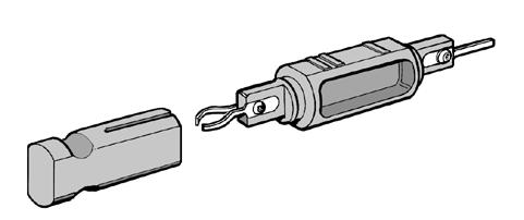
Adapter for mechanical controls
Transmits:
Engine data information to third party NMEA 2000 compatible equipment.
Information about boat speed from a GPS or similar, to be presented on an instrument and in the tachometer or the EVC system display, An NMEA interface/ multisensor must be installed to supply speed information to the EVC system.
Relay for external accessories
Use of an adapter for mechanical controls will enable you to use any mechanical control in combination with the EVC system. The adapter will convert the mechanical push-pull movement into an electric signal.
A neutral switch with a connector (pig tail) is connected to the adapter lever.
Install the adapter as close as possible to the control to reduce the amount of force needed to move control lever and make sure the location is dry and easy accessible.
The adapter should also be used for trolling function when a mechanical control is used.
Buzzer (option)
The EVC architecture is prepared to operate a relay to power up additional equipment when the engine key switch is turned on.
Relay 12 V, 20A D4, D6, D9
Relay 24 V, 20A D6, D9, D12, D16
Fuel level sender and fresh water level sender
Powertrain control unit, PCU
Helm station control unit, HCU
The fuel and water tank levels can be displayed on the EVC display or in separate instruments.
Level sender suitable for tanks with a height of max.
600 mm (23").
Fuel level sender resistance (two types):
3 –180 ohms, 3 ohms = empty tank
240 –30 ohms, 240 ohms = empty tank
Fresh water level sender resistance:
3 –180 ohms, 3 ohms = empty tank
IMPORTANT! The fresh water sender potentimeter is protected against corrosion. Make sure to use the right type of sender.
Rudder angle sensor
The PCU node is to be located in the engine room. The PCU communicates with the engine and with the drive or the reverse gear. It also communicates with the helm station control unit HCU, via the standard bus cable.
The HCU node is to be located close to the helm and the components that it controls. It communicates with the PCU via the standard bus cable.
The HCU is equipped with a LED (STATUS). When installed the LED is flashing quickly when power is on and is off when power is off. Connector X8 is plugged.
The rudder angle sensor, 3–180 ohms, is connected to the EVC system through the engine/transmission cable harness. A special instrument or display on the dashboard shows the rudder angle.
IMPORTANT! On the PCU and HCU there is a label (1), with serial no. and chassis identification. There are also corresponding labels on the engine. The reason for having individually programmed PCU:s and HCU:s is that the software must correspond to each engine specification or helm specification (equipment and functionality).
Please refer to chapter Identification of the PCU and the HCU


