Electrical systems – 5000 Functional description T-code 789, 790, 791, 817, 818
Valid from serial number 985777-
Date 2007-05-11
Order number 249896-040
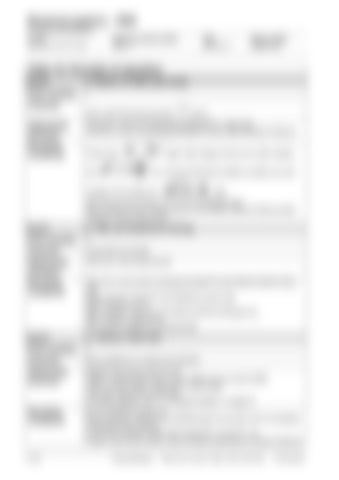
Table 10: Principle of operation Event:
2. Switch on (PIN-code entry)
Prior event(s)
1
Action(s) Enter valid PIN-code and press
[A17]
Influencing elements
Emergency switch-off closed [S21] [INP.SUPPLY +24V] high Tiller arm in drive not activated [S10] [INP.TILLER ARM IN DRIVE POS] low
Resulting conditions
Power lamp and
lights. Main display shows hour meter reading for 4 seconds followed by battery condition as a per-
centage of full charge and
[A6]
Mechanical brake remains on [Y1, A1:OUT.BRAKE] high Main contactor output remains high [A1:OUT.MAIN CONTACTOR] and Main contactor remains open [K10]
Event:
3. Tiller am lowered for driving
Prior event(s)
2
Action(s)
Lower tiller arm handle
Influencing elements
Tiller arm in drive sensor [S10]
Resulting conditions
Tiller arm in drive sensor activates [S10] [INP.TILLER ARM IN DRIVE POS.] high Brake solenoid control [A1:OUT.BRAKE] remains high Brake remains on [Y1] Main contactor output [A1:OUT.MAIN CONTACTOR] goes low Main contactor closes [K10] 24V (power) supplied to [A1],[A3] & [A5]
Event:
4. Traction, forks first
Prior event(s)
3
Action(s)
Move butterfly [L1] in forks drive direction.
Influencing elements
Butterfly Hall sensors [A2:S10-18] Platform staying down sensor [S19]. Platform not up sensor [S59] Gates up sensor [S53], Gates down sensor [S56] Fork load supervision sensor [B4] Parameter settings. See “11.4.4 Speed limitation” on page 34
Resulting conditions
[A1:OUT.BRAKE A] goes low Brake solenoid control [A1:OUT.BRAKE] goes low & brake coil [Y1] energises, mechanical brake releases Current fed to traction motor field winding (S2 +ve and S1 -ve) Pulsed current fed to traction motor armature proportional to butterfly deflection
11- 28
Service Manual
7SLL12.5, 16, 20, 13.5S, 12.5F, 16F, 20F
© TIEE SARL

