16 minute read
ElectricalSystem–5000

from Toyota Forklift 7SLL12.5 7SLL16 7SLL20 7SLL13.5S 7SLL12.5F 7SLL16F 7SLL20F Service Manual SN 985777

Technical specifications – Curtis 1243
13.10Technicalspecifications–Curtis1243
* Under special test conditions.
14.1General
To avoid functional problems with the lowering valve (Y41), such as unintentional lowering of forks, the valve must be cleaned and the function checked before replacing the valve.
14.3Adjustments7PM18
14.3.1Adjustingthepressurelimitvalve
The pressure limit valve is set to the correct value at the factory, but may need to be adjusted if the valve or the complete hydraulic unit is replaced.
The truck should be capable of lifting a load of between 1850-1900 kg.
1.Lockingnut.Usespecialtool,seedrawinginchapter“Tools”.
2.Adjusterscrew,pressurelimit. Adjustingclockwiseresultsinincreasedpressure. Adjustinganticlockwiseresultsindecreasedpressure.
3.Pressurelimitvalve.Usespecialtool,seedrawinginchapter “Tools”.
•Loosen the locking nut (1) using a special tool (see drawing 3.2). Place a load of 1800 kg on the forks and check that the truck can lift it.
•If the truck lifts 1800 kg, place a further 100 kg on the forks. Check whether the truck can lift the load.
•If the truck lifts 1900 kg, adjust the pressure limit by turning the adjuster screw (2) anticlockwise using a 4 mm allen key until the truck cannot lift the load.
Adjustments 7PM18
14.3.2Tools
•Use a 22 mm standard socket and turn it down to the values shown below in drawing A, when you wish to loosen or tighten the pressure limit valve.
•Use a 10 mm standard socket and turn it down to the values shown below in drawing B, when you wish to loosen or tighten the locking nuts.
14.4.1Adjustingthepressurelimitvalve
The pressure limit valve is set to the correct value at the factory, but may need to be adjusted if the valve or the complete hydraulic unit is replaced.
The truck should be capable of lifting a load of between 2050-2100 kg.
1.Lockingnut.
2.Adjusterscrew,pressurelimit. Adjustingclockwiseresultsinincreasedpressure. Adjustinganticlockwiseresultsindecreasedpressure.
•Loosen the locking nut (1) using a 13 mm spanner.
•Place a load of 2000 kg on the forks and check that the truck can lift it.
•If the truck lifts 2000 kg, place a further 100 kg on the forks. Check whether the truck can lift the load.
•If the truck lifts 2100 kg, adjust the pressure limit by turning the adjuster screw (2) anticlockwise using a 4 mm allen key until the truck cannot lift the load.
Adjusting the pressure limit valve
14.6Adjustingthepressurelimitvalve
The pressure limit valve is set to the correct value at the factory, but may need to be adjusted if the valve or the complete hydraulic unit is replaced.
The truck should be capable of lifting a load of between 2050-2100 kg.
1.Lockingnut.
2.Adjusterscrew,pressurelimit. Adjustingclockwiseresultsinincreasedpressure. Adjustinganticlockwiseresultsindecreasedpressure.
•Loosen the locking nut (1) using a 13 mm spanner.
•Place a load of 2000 kg on the forks and check that the truck can lift it.
•If the truck lifts 2000 kg, place a further 100 kg on the forks. Check whether the truck can lift the load.
•If the truck lifts 2100 kg, adjust the pressure limit by turning the adjuster screw (2) anticlockwise using a 4 mm allen key until the truck cannot lift the load.
PowerTrakcylinder–6680
Dismantling of PowerTrak cylinder
15.2DismantlingofPowerTrakcylinder
Make sure that the truck is unloaded and that the forks are lowered.
•Turn the key to neutral and pull out the battery plug.
•Dismantle top covers and head.
•Release the hydraulic hose (1).
•Carefully unscrew the screws (2) to the clamp (3) that holds the spring guides.
•Lift out the PowerTrak cylinder (4). Assemble in reverse order.
The measurement between washer and screw head should be 49 mm.
WARNING! Risk of injury. There is a risk of personal injury in conjunction with work on the PowerTrak system. Follow the instructions carefully.
16-Batterycharger(Inbuilt)–8340
16.1General
SMCI is a battery charger intended for valve-regulated or freely ventilated lead acid batteries. It is adapted for batteries from about 100 Ah up to 320 Ah.
The charger which uses advanced switch techniques is connected to a normal (grounded 230 V single phase) socket (B) and the built-in micro controller then controls charging following the pre-set charging curve. During charging the charging process is displayed with a status indicator on the standby housing (A).
The micro controller also controls charging with respect to charging time and temperature in the charger so that charging can be limited, e.g. if a fault occurs in some cell in the battery or when there is insufficient cooling of the charger.
SMCI 300 is delivered pre-set for 24 v and with software intended for charging valve-regulated or freely ventilated lead acid batteries.
The size and type of the battery are selected using the switch on the side of the fan(C) which is accessible via a slotted head screwdriver.
16.2Charging
Connect the charger to the mains. When charging starts after a few seconds, the orange status indicator on the standby housing(A) lights up. Yhis indicator remains lit until the battery is fully charged and the indicator turns to green.
Charging time varies depending on the type of battery and the degree of discharge. Normally the charger is started after working hours and the battery is fully charged the next morning. A highly discharged freely ventilated battery of 320 Ah may need up to 14 hours re-charging time, a VR battery even longer.
Some time after charging (depending on, for example, type of battery) SMCI 300 switches to maitenance charging. The green indicator remains lit to show that the battery is fully cgarged.
When charging is completed, the mains plug is placed in the standby housing.
Batterycharger(Inbuilt)–8340
Troubleshooting and service
T-codeValidfromserialnumber
677, 678, 679723984--
DateOrdernumber
2005-02-02222995-040
16.3Troubleshootingandservice
First check whether the charger indicates an error. A red, blinking indicator means that the charger cannot detect that any battery is connected. Check the cables, pole terminals and other connections to the batteries. Measure battery voltage.
If the charger still doesn´t work, send it to your supplier for repair.
16.4Technicaldata
Size 250x115x67 mm
Weight 1,6 kg
Ambient temperature -25°C till +40°C
Mains voltage 90-255 V AC 45-400 Hz
(Reduced charging current for mains voltage below 200 V
Rated voltage 24 V DC
Rated current 30 A
Max output 750 W
Efficiency > 86%
Battery type
Freely ventilated lead batteries (with water refilling). Valve regulated (VR) lead batteries.
Protection IP 20
General
Temperature regulated cooling fan, protected against faulty polarisation
8700
TruckCom 3.5 User Manual -for trucks using the “PowerDrive” platform. This Manual is valid for version 3.5 of TruckCom p/n 182147-008.
17.1General
TruckCom is a communication program which communicates with trucks equipped with CAN (Controller Area Network) communication. It enables the following tasks to be performed:
•downloading truck control software.
•viewing and adjusting operator / truck parameters and hour meters. Additionally, the truck’s parameter set (including hour meter values) can be saved to file and reloaded later.
•viewing diagnostic data for various digital inputs / outputs and analogue data including voltages, currents and certain temperatures. The program is a Windows program running under Windows® 95/98, Windows® XP/2000 and Windows® NT.
17.2Connection
A CAN interface of the CPC-PP type is needed to connect it to the truck, with attendant cable. Connect the interface via the printer port on a PC. Connect the cable between the interface and the truck's CAN terminal.
The CAN interface is supplied with power from the truck electronics and is protected from any high voltages in the truck if a fault should occur.
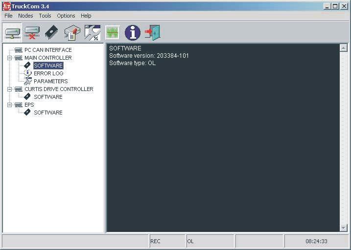
17.3.1Mainprogramscreen
The Main window opens when the program is started. This shows the menu bar, tool buttons, workspace, log window and status window.
17.3.2Nodes
Devices which are connected to and communicate via the CAN interface are called nodes. The nodes detected on the bus are shown in the node window. The current node status and input component/information is shown with different icons.
17.3.3Icons
IconDescription
Node OK is shown when contact is made with a node and no errors have been reported.
Node not connected is shown when there is no contact with a node in the network.
Node not OK is shown when an error has been reported by a node. Click on node to obtain more information.
Program version is shown when information is available on which software is installed. Click to obtain more information.
Information is shown when a node has information on, for example, error codes.
Truck report
GB“17.7Truck report function” on page 7
Parameters is shown when a node has information on a parameter.
17.3.4Toolbuttonsandmenubar
The tool button bar allows direct access to the program’s most common functions. The menu bar allows access to all the program functions. Explanations of each menu bar item are given in the relevant section.
17.3.5Informationwindow
The right section of the main window contains a status window where different messages are shown.
To see previous messages, use the scroll arrows in the right margin.
17.3.6Statusbar
There is a status bar at the bottom of the main window, which shows variable status when the program is run.
The following are shown from the left: Help text "pop-up" via the mouse cursor, connected/not connected to network, truck type connected, initiation result of CAN interface and the present time.
17.4Connectionfunction
To connect the PC the network, select the Scan units function. This can be done with the menu <Nodes | Scan units> or with the tool button [Scan nodes]
This should also be done when the truck is supplied with voltage and in normal drive mode.
The program will now run a check and installation of the CAN interface. A diagnosis will also be carried out to check which units are connected in the system. The result of this diagnosis is shown in the Node window.
17.5Disconnectionfunction
Select the Disconnect function to disconnect from the network. This can be done with the menu <Nodes | Set PC off-Line > or with the tool button [Set PC off-Line].
The CAN interface is then reset and the CAN cable can be disconnected if so required. This enables connection to another truck without having to close the program.
Downloading program function
17.6Downloadingprogramfunction
To download a new program to one of the nodes, select the Download software function. This can be done with the menu <Tools | Download software... > or with the tool button [Download]

17.6.1Normaldownloading(truckwithkey)
Select Open.. to open the file to be downloaded into a node. The file name, file type and version number are shown in the window for file information. If it is file for a controller, indicate which type of controller is to receive the file. Start downloading by selecting Start... and by restarting the truck by turning the key off and on twice. Restart must be made within 20 seconds from when the Start button has been activated.
Close the download window when the download is ready, and then disconnect the PC from the network. A new connection can now be made to verify the new program.
17.6.2Normaldownloading(truckwith keypad)
Select Open to open the file to be downloaded into a node. The file name, file type and version number are shown in the file information dialogue box. If it is file for a controller, indicate which type of controller is to receive the file. Start downloading by depressing and then releasing the red key on the keypad.
Downloading program function
The truck must be restarted within 20 seconds from the time the Start key has been actuated.
When downloading has been completed, close the download dialogue box and then disconnect the PC from the network. It is now possible to reconnect to verify the new application.
17.6.3Emergencydownloading(truckwith
keypad)
•Disconnect the battery connector.
•Select OK in the dialogue box.
•Keep the red key on the keypad depressed while reconnecting the battery connector.
•Release the red key to commence downloading.
17.6.4Downloadinginoldversionsoflogic
Card
To download to older versions of electronic cards which do not support restart with key, the button Old card... should be used instead of Start... Downloading is carried out in the same way, except that restart is done by using the battery lug instead of the key.
17.6.5Emergencydownloading(truckwith
keypad)
E141 will be shown in the truck’s display when starting, if for any reason there is no program in the electronics card (interrupted downloading). Communication with the truck via the PC will then be minimised. Use “E141” to download the program in the card.
On some trucks, a counter, which continuously counts up, is displayed. NOTE!
Once programmed, the logic cards in some trucks can only be upgraded with the same basic firmware. In other words, it is not possible to replace the basic firmware (other machine type).
Truck report function
17.7Truckreportfunction
It is possible to generate a report to a file or disk with the truck’s configuration and status. Select menu <Tools | Generate truck report...> or with the tool button Truck report. Save the report in Report.file.

NAME
Example of information generated in the truck report:
[GENERAL]
REPORT DATE-TIME=2004-01-19 11:11:58
CPC-PP SERIAL No=8002041
MACHINE NUMBER=555555
CUSTOMER=CUSTOMER 1
TECHNICIAN=NONAME
[CAN NODES]
MAIN CARD=0
CURTIS DRIVE CONTROLLER=16
[MAIN CARD CONFIGURATION]
SOFTWARE=181179-001
HARDWARE=167833-004
SERIAL NO=53676
[DRIVE CONTROLLER CONFIGURATION]
SOFTWARE=5
DRIVE CURRENT LIMIT (A)=300
FIELD MAXIMUM (A)=34
SERIAL NO=52857
MFG Date:=26/05/03
HOUR METERS]
A IGNITION TIME=81
B TOTAL MOVEMENT=7
C DRIVE MOTOR TIME=7
D PUMP MOTOR TIME=0
S SERVICE TIME=7
The contents of certain rows can vary according to truck type.
Parameters function
17.8Parametersfunction
To change the truck parameters, select the Parameter function. This can be done with the menu <Tools | Change parameters > or with the tool button Parameters.
NOTE!
The truck must in Normal mode (i.e. not Parameter mode) when connecting TruckCom. Otherwise TruckCom will report “Unable to determine truck brand”
The parameter numbers follow the description in the respective truck Service Manuals, section 5000.
The parameter window shows the information and the current settings for all parameters. The parameters are divided into 4 tabs.
•[Driver] - driver; driver parameters and PIN code storing
•[Truck] - truck; service parameters
•[Time] - time; time-related service parameters
•[Option parameters] - option parameters. (no. 15 to 19)
WARNING!
Do not attempt to make any adjustments to the option parameters unless you have sufficient knowledge of the truck’s options/ modified functions. Specially modified trucks may require that you have access to special service information. Improper adjustment of the option service parameters may result in a malfunction.
17.9Diagnosticsfunction
To access diagnostics, select the Diagnostic function. This can be done with the menu <Tools | Diagnostic...> or with the tool button Diagnostic.
NOTE!
If the value “---” is shown in a field, or a “read status LED” is red, the communication has been interrupted for some reason and error data cannot be shown.
NOTE!
The tab information displayed in the diagnostics mode depends on the type of truck connected.
17.9.1Representationofsignalcolours
The screen dumps shown in the following section have been modified to improve legibility in black & white print.
Clicking on the tiller arm tab will display a dialogue showing the following:
• Speed lever -the status of the speed control and travel direction selector. The status of each individual hall element is displayed.
• Buttons -The status of the control buttons is displayed. “Sxx” refers to the switch designations as given in the circuit diagram.
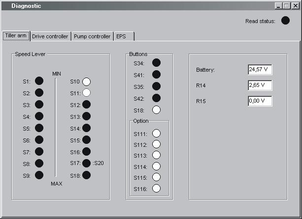
• Option -Status of option buttons
• Battery -The measured battery voltage
•R14 -Shows the measured signal voltage from the lift/lower control
• R15 -Not used at present
17.9.3“DriveController”tab(transistor regulator-travel)
Clicking on the Drive Controller tab will display a dialogue showing the following:
•Status of digital inputs and outputs of the transistor regulator. pin refers to the motor controller pin designations as given in the circuit diagram.
• Field PWM - The effective power output supplied to the field circuit as a percentage.
• Armature PWM - The effective power output supplied to the armature circuit as a percentage
• Field current - The current flowing in the field circuit in Amperes.
• Armature current - The current flowing in the Armature circuit in Amperes
• Raw throttle data - The received speed control signal as a percentage.

• Temperature - The temperature of the output stage of the transistor controller in degrees Celsius
• Inp pin 10 - The input voltage from the mode/pressure sensor. “digital o” indicates the digital status of the input.
• Inp pin 11-The input voltage from the man-on platform sensor. “digital o” indicates the digital status of the input.
17.9.4“Pumpcontroller”tab(transistor regulator-pump)
If the truck is equipped with a lift/lower transistor regulator, the Pump controller tab displays the following:

•Status of digital inputs and outputs of the transistor regulator. pin refers to the motor controller pin designations as given in the circuit diagram.
•Field PWM, Armature PWM, Field current, Armature current, Temperature - Measured values from the transistor regulator for the pump motor. See the explanation on page 10
• Raw throttle data - The received lift/lower signal as a percentage.
•Out pin9 - The output signal to the proportional lowering valve as a percentage.
• Inp pin 10 - The input voltage from the pressure sensor. “digital o” indicates the digital status of the input.
• Inp pin 11 - The input voltage from the pressure sensor. “digital o” indicates the digital status of the input.
Clicking on the “EPS” tab will display a dialogue showing the following:
“Status”
•“Operational” - Indicates the status of the servo’s control system
•“EPS enabled” - Indicates the status of the servo’s power stage output.
•“Reference switch reached” - indicates status of drive wheel in centre reference switch.
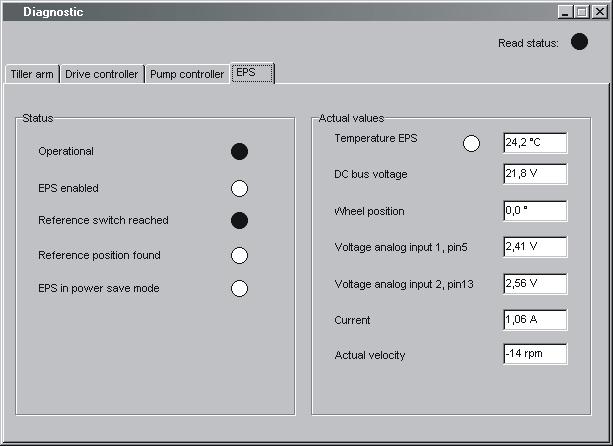
•“Reference position found” - indicates whether a successful steering in centre has been performed.
•“EPS in power save mode” - Shows whether the steering servo is in the standby mode (following a certain amount of inactivity).
“Actual values” (Measured values)
•“Temperature EPS” - The temperature of the steering servo output stage in degrees Celsius.
•“DC bus voltage” - Supply voltage to steering servo
•“Wheel position” - Shows the estimated steering angle of the drive wheel.
•“Voltage analog input 1, pin5”- The measured DC input signal (0) from the steering potentiometer.
Other menu functions
•“Voltage analog input 2, pin13”- The measured DC input signal (1) from the steering potentiometer.
•“Current” - the measured current supplied to the steer servo motor in Ampere
•“Actual velocity” -The measured rotational speed of the steer servo motor shaft in r.p.m.
17.10Othermenufunctions
17.10.1Savetofile
The truck parameters can be saved in the PC for downloading at a later date. Select <File | Save to file | Parameters >. All parameters in the nodes which are connected to the bus will be scanned in and saved in a file. If only the hour meters are needed, select <File | Save to file | Hour meters >.
17.10.2Downloadfromfile
A set of parameters can be downloaded from the PC to the truck. Select <File | Load from file | Parameters >. The parameters in the file will be copied to the nodes connected to the bus. If only the hour meter settings are needed, select <File | Load from file | Hour meters >.
17.10.3ResetCANadapter
If problems should occur when resetting the CAN adapter connected to the PC, this can normally be done manually by making sure that the adapter is supplied with voltage and then selecting <Nodes | Reset CPC-PP >.
17.10.4Deleteerrorcodelog
To delete the truck’s error code log, start the truck in parameter mode and then select < Tools | Erase error log >.
17.10.5Resethourmeter
To reset the truck’s hour meter, start the truck in drive mode and then select < Tools | Reset hour meters >.
17.10.6Readerrorcodelog
To show the truck’s error code log, select < Tools | Read error log >.
Specifications
T-codeValidfromserialnumber 677, 678, 679723984--
17.10.7Adjustdateandtime
To quickly adjust the truck’s data and time, select < Tools | Adjust date & time >. The time given in the PC will now be downloaded into the truck.
NOTE!
This does not apply to trucks without a real-time clock.
17.10.8Adjustingthehourmeteronolder
Cards
To adjust the hour meter on trucks with older cards, select < Tools | Adjust Hour meters >. The time given in the PC will now be downloaded into the truck.
17.10.9Help AbouttheTruckComapplication
To see program information, select <Help | About TruckCom... > or use the tool button [Information].
17.10.10Exit
To exit the program, select <File | Exit > or use the tool button [Exit].
17.11Specifications
17.12Installation
NOTE!
The program must be installed from the hard disk.
NOTE!
The software application in the computer can be damaged, which is why the PC installation should be performed by someone with the required knowledge. TOYOTA does not accept any responsibility for any errors that occur during the installation.
NOTE!
All references to PC operating system actions, menus and commands are based on the English language version of Windows® .
17.12.1InstallationonaPCwithWindows® 95/98
If a previous version of the TruckCom application has been installed on the PC, it will be necessary to edit the System.ini file.
Start the Msconfig.exe application by selecting the Start button, selecting Run and then typing msconfig. Click on System.ini and open the folder (386Enh).
Unmark the option at Device=C:\Windows\Cpcppvd.vxd.
Save the change and close the application.
Now continue with installation
The software application is supplied on a CD or via a network. Start installation by running X:\SETUP.EXE, where X:\ is the drive on which the installation application can be found. Then follow the on-screen instructions.
2000
To make the application work, it is necessary to first enter a value in the Windows® Registry and then make a few changes in the Windows® Control panel.
Due to the built-in Windows® security, this must be done manually. The instructions below provide step-by-step guidance to enable these changes and make the interface operate under Windows XP and Windows 2000.
The changes can be made either before or after TruckCom is installed.
•Open the Registry Editor. To do this, select the Start button, then Run, type regedit and hit Enter.
•Mark the Enum folder which can be found under HKEY_LOCAL_MACHINE\SYSTEM\CurrentControlSet inside the Registry Editor.

Select the Edit option, then Find and type PortName to search for the correct folder.
NOTE!
The location of the folder differs between different computers (some may be .. \Enum\Root\.., while others could be ...\Enum\ACPI\... etc.). Thus be sure to search for the correct folder.
When the folder is found, check that LPTx(x=1,2,3,4) is displayed in the PortName data field and that the folder name is Device Parameters.
Right-click with the mouse in the right box to enter a new value of the DWORD type and with the name
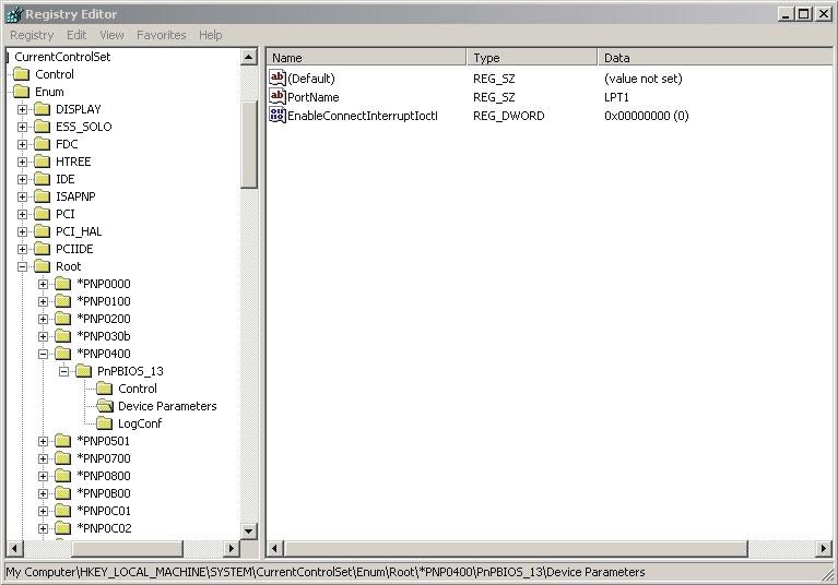
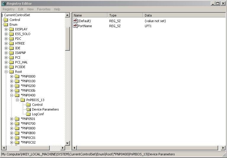

Installation
Changes in Windows® Control Panel
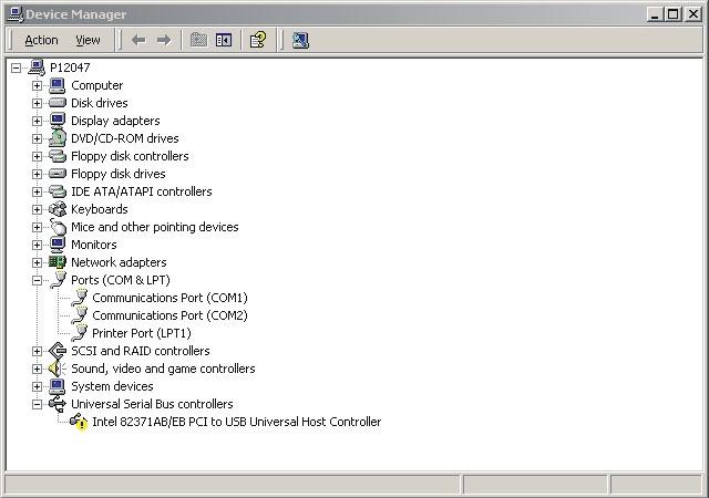
Select the Start button. Choose Settings, then Control Panel and double-click on System, then select Hardware. Click on Device Manager and open Ports (Com & LPT).

Double-click on the LPT port to be changed, and select the Port Settings tab. Check the "Use any Interrupt assigned to the port" option and click on OK.

The software application is supplied on a CD or via a network. Start installation by running X:\SETUP.EXE, where X:\ is the drive on which the installation application can be found.
Then follow the on-screen instructions.
17.12.3InstallationonaPCwithWindowsNT
The software application is supplied on a CD or via a network. Start installation by running X:\SETUP.EXE, where X:\ is the drive on which the installation application can be found. Then follow the on-screen instructions.
17.12.4Incaseofcommunicationproblems
withCAN
Make sure the computer settings for the printer port in the BIOS Setup are as follows:
Port address:0378
IRQ:7
Mode:Output only
For detailed information on how to change the Setup settings, refer to the User's Guide supplied with the computer.
17.12.5Touninstall
To uninstall TruckCom under Windows®, select the Start button, Settings, Control Panel, Add/Remove Programs. To uninstall you must then select the TruckCom Program and click Change/Remove.