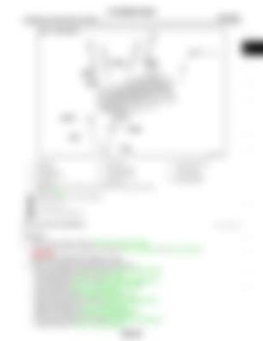
CYLINDER HEAD [HR16DE]
< REMOVAL AND INSTALLATION >
A
EM
C
D
E
F
G
H JPBIA4098GB
1.
Spark plug
2.
Valve collet
3.
Valve spring retainer
4.
Valve spring
5.
Valve spring seat
6.
Valve oil seal
7.
Valve guide (INT)
8.
Valve guide (EXH)
9.
Valve seat (EXH)
10. Valve (EXH) A.
11. Valve (INT)
I
12. Valve seat (INT)
J
Replacement must be following the disassembly and assembly procedure. Refer to EM-211 : Always replace after every disassembly.
K
: N·m (kg-m, ft-lb) : Should be lubricated with oil.
L
Removal and Installation
INFOID:0000000006449923
REMOVAL 1. 2.
3.
M
Release fuel pressure. Refer to EC-551, "Work Procedure". Drain engine coolant and engine oil. Refer to CO-11, "Draining" and LU-26, "Draining". CAUTION: Perform this step when the engine is cold. Remove the following components and related parts. • Front road wheel and tire (RH): Refer to WT-7, "Exploded View". • Fillet mold: Refer to EXT-26, "Exploded View" • Front fender protector (RH): Refer to EXT-22, "Exploded View". • Drive belt: Refer to EM-155, "Removal and Installation". • Air duct: Refer to EM-161, "Exploded View". • Intake manifold: Refer to EM-163, "Exploded View". • Fuel tube and fuel injector: Refer to EM-173, "Exploded View". • Water outlet: Refer to CO-26, "Exploded View". • Exhaust manifold: Refer to EM-166, "Exploded View". • Rocker cover: Refer to EM-178, "Exploded View". • Front cover and timing chain: Refer to EM-181, "Exploded View". • Camshaft: Refer to EM-191, "Exploded View".
EM-209
N
O
P

