CYLINDER BLOCK < UNIT DISASSEMBLY AND ASSEMBLY > • Install knock sensor (1) with harness connector facing toward the rear of engine. A
[MR16DDT ]
: Cylinder block left side : Engine front
CAUTION: • Never tighten mounting bolts while holding the harness connector. • If any impact by dropping is applied to knock sensor, replace it with a new one. PBIC3246J NOTE: • Check that there is no foreign material on the cylinder block mating surface and the back surface of knock sensor. • Check that knock sensor does not interfere with other parts. 17. Assemble in the reverse order of disassembly.
Inspection
INFOID:0000000006337298
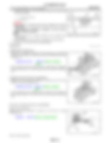
CRANKSHAFT END PLAY • Measure the clearance between thrust bearings and crankshaft arm when crankshaft is moved fully forward or backward with a dial indicator (A). Standard and Limit
: Refer to EM-134, "Cylinder Block".
• If the measured value exceeds the limit, replace thrust bearings, and measure again. If it still exceeds the limit, replace crankshaft also. JPBIA4436ZZ
CONNECTING ROD SIDE CLEARANCE • Measure the side clearance between connecting rod and crankshaft arm with a feeler gauge (A). Standard and Limit : Refer to EM-134, "Cylinder Block". • If the measured value exceeds the limit, replace connecting rod, and measure again. If it still exceeds the limit, replace crankshaft also. JPBIA4437ZZ
PISTON TO PISTON PIN OIL CLEARANCE Piston Pin Hole Diameter Measure the inner diameter of piston pin hole with an inside micrometer (A).
Standard
: Refer to EM-134, "Cylinder Block".
PBIC3265J
Piston Pin Outer Diameter
EM-112
