1 minute read
Control and operation


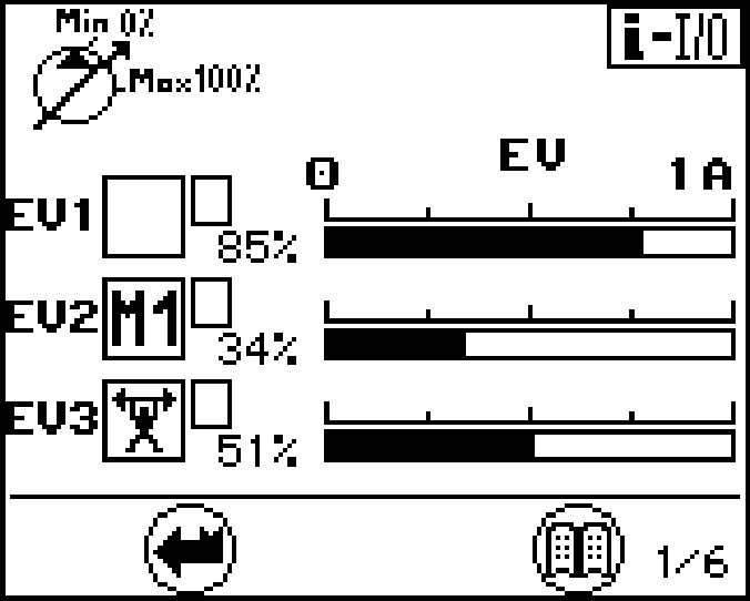
Page 1 provides the service life in hours for:
Press the Menu button. Page 2 is displayed.
The technical data menu, page 2, provides information on : Press the Menu button again. Page 1 is displayed.
To exit the menu: Press the Back button. The submenu will be aborted.
Status of hydraulic pumps and electrical inputs and outputs menu
Quantity limitation menu
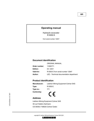
Page1givesinformationabouttheoperatingpositionofthehydraulicpumps.Itgives the following indications for each working pumps :
If the flow limitation is activated for the pump. If it occurs, the symbol "R" is dis- played in the field TI, see main screen. The screen 1/6 shows an example with theflowlimitationM1activated,whichlimitsthepumpP2to34%ofthemaximum flow.Shouldseveralflowlimitationsbeactuatedatthesametime,sotheonewith the smallest flow value has priority.
The graphic bar with electric current value indicates for the pump the amount of the momentary flow control signal.
Press the Menu button again. Page 2 is displayed.
The present LR solenoid current (current value for power control) is showed on screen 2.
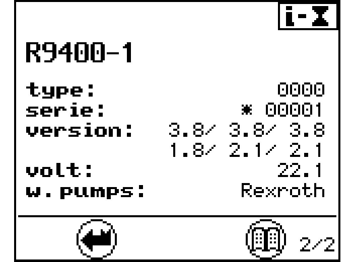
Press the Menu button again. Page 3 is displayed.
The screen 3 indicates for the fan pumps the amount of the momentary flow control signal.
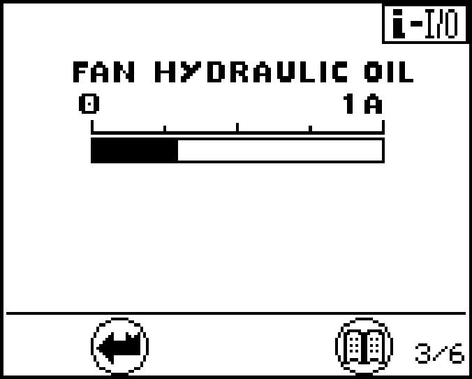
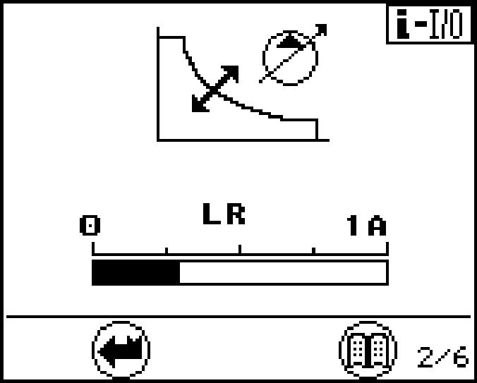
Fig. 3-19 Electrical inputs
Press the Menu button again. Page 4 is displayed.
Press the Menu button again. Page 5 is displayed.
Press the Menu button again. Page 6 is displayed.
Pages 4, 5 and 6 provide an overview of the status of different electrical inputs. input has been deactivated.
The status of the inputs can be changed using the menu "set data" - "set E-code".
The screen 4 indicates the status of the inputs for the different movements.
Thescreen5indicatesthestatusoftheflowlimitation.M1,M2,...correspondtomachinespecific(internal)oilflowlimitations.I1,I2,...correspondtopredefinedoilflow limitations (see also menu "set option").
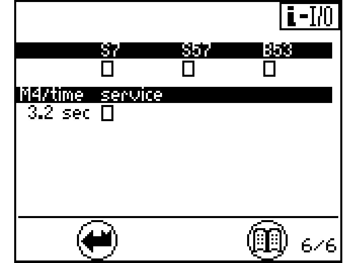
The screen 6 indicates the status other inputs. For the frequency inputs B53, the equency is recognised by the system
B53 Swing motor sensor
S7 Safety lever servo control S57 Swing brake
To exit the menu: Press the Back button. The submenu will be aborted.
Error menu (operating errors and electrical system errors)
There are 3 selection options in this menu: list Exxx, machine errors recorded by the sensors are listed. list E-elec, all main screen cable errors stored when operating are listed.

list S-Exxx, all errors which appeared when the service connector was connected are listed.
To select the desired error type:
Press the Down or Up arrow key. The following or preceding error type will be displayed with a black background.
Press the Menu button.
The submenu on a black background will be displayed. Ifmorethan6errorcodesarepresent,arrowkeyDownorUpcanbeusedto scroll to the next page.
Machine error list Exxx:
Select list Exxx
Press the Menu button.
The first page of the submenu appears.
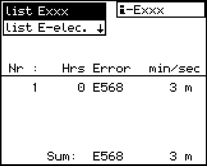
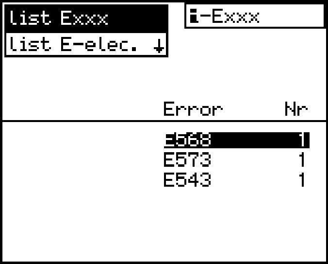
All errors and their error codes are listed on the first page. Use the Down or Up arrow key to select the error code desired. Press the Menu button again.
The second page of the submenu appears.
Operatinghoursandthedurationofthefirstandlasttenoccurrencesoftheerrorse-