10 minute read
Control and operation


To check the mechanical swing gear brake: When the uppercarriage is stationary.
Press button S17 to apply the mechanical swing brake. Push the left joystick to the right and then to the left as far as the stop. If the swing brake function is OK, the uppercarriage does not start swinging.
Semi-automatic swing brake control (optional equipment)
Press button S17 to release the swing brake. LED in the button goes out.
The swing gear brake is in mode semi-automatic and can now be controlled as follows by the rocker switch S57:
Tilt down the rocker switch S57 on the joystick handle. Thebrakeisappliedwhentheuppercarriageisatstandstill,respectivelyitapplies as soon as the uppercarriage speed gets lower than a limit value.
Tilt up the rocker switch S57. The brake remains released permanently.
Note!
TheredLEDbesidethebuttonS17islightinginanycasewhenthebrakeisapplied. If this light does not go out when the rocker switch S57 is tilted up, the button S17 must first be pushed to pre-select the semi-automatic mode.
Caution!
Thebrakeonlyapplieswhentheuppercarriageisnearstandstillandifnoswingmotion is actuated with the joystick.
To stop the uppercarriage when working on a slope: Tilt down the rocker switch S57
Use the joystick to reduce the uppercarriage speed. Move the joystick back to "0" position only after the brake operates.
Emergency stop of the uppercarriage swing motion
Theswingbrakecanbeapplied independently of theuppercarriage RPMby switching the "Swing brake" button S17 to position "applied".
Caution!
Perform this braking via "Swing brake" button S17 only exceptionally, i. e. in emergency cases, since it causes fast abrasion of the brake discs.
copyright © Liebherr-Mining Equipment Colmar SAS 2021
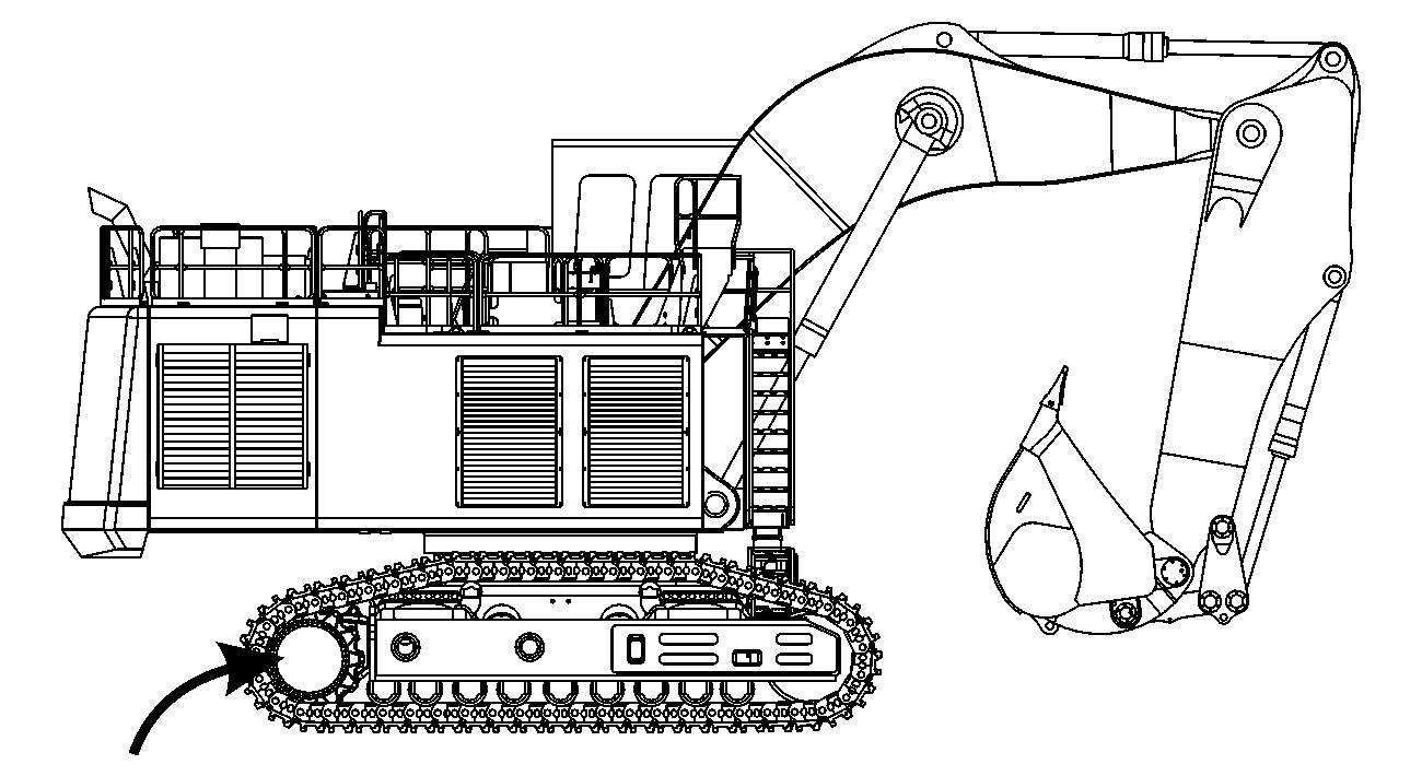
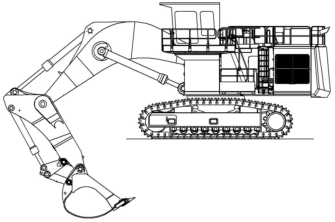
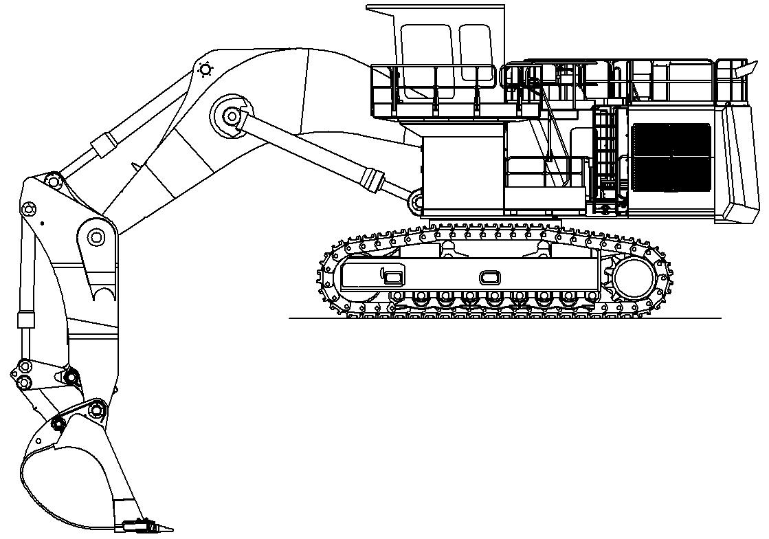
3.4.2Working position
Fig. 3-65 Working position – machine
Work with the machine is generally to be carried out over the idler.
Note
Drive backwards when you are working lengthwise with the backhoe bucket.
3.4.3Joystick functions when setting up themachine Operating the stick cylinder
The stick cylinder is operated using the left joystick 4
Push the joystick back a Stick will be drawn in.
Push the joystick forwards b Stick will be extended.
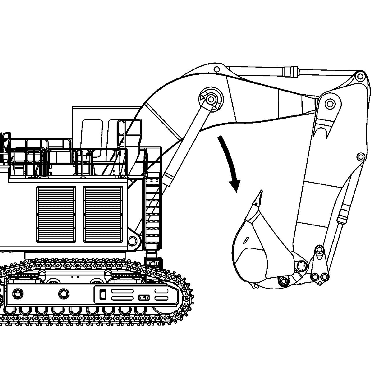
Operating the boom cylinder
The boom cylinder is operated using the right joystick 3
Fig. 3-67 Operating the boom cylinder

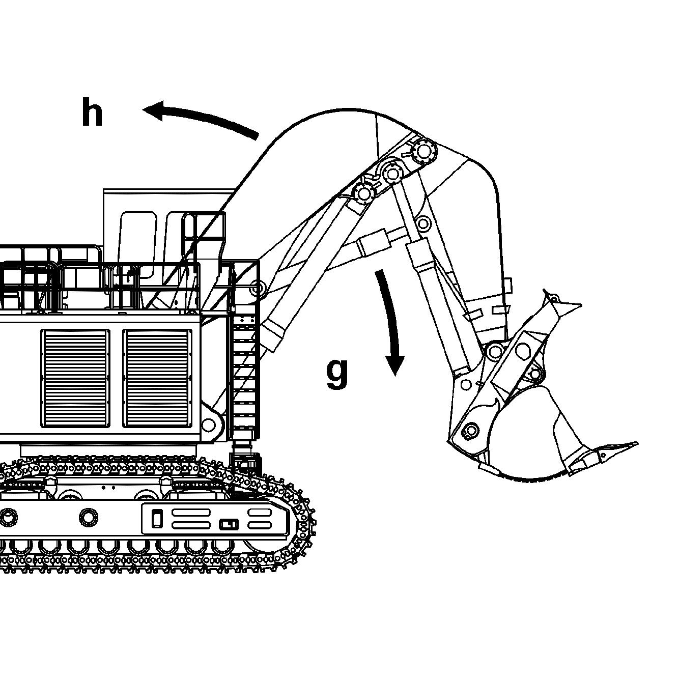
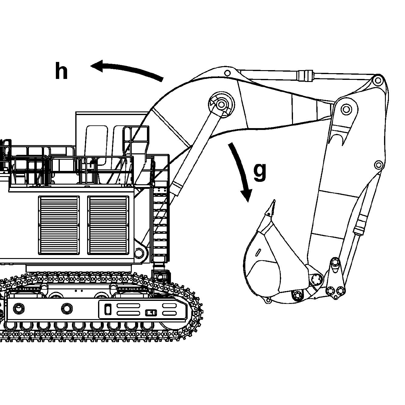
Push the joystick back h Equipment will be raised. Push the joystick forwards g Equipment will be lowered.
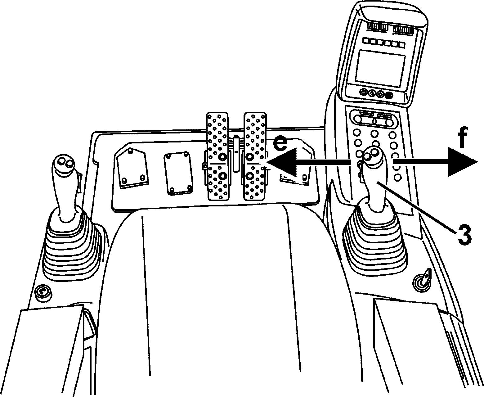
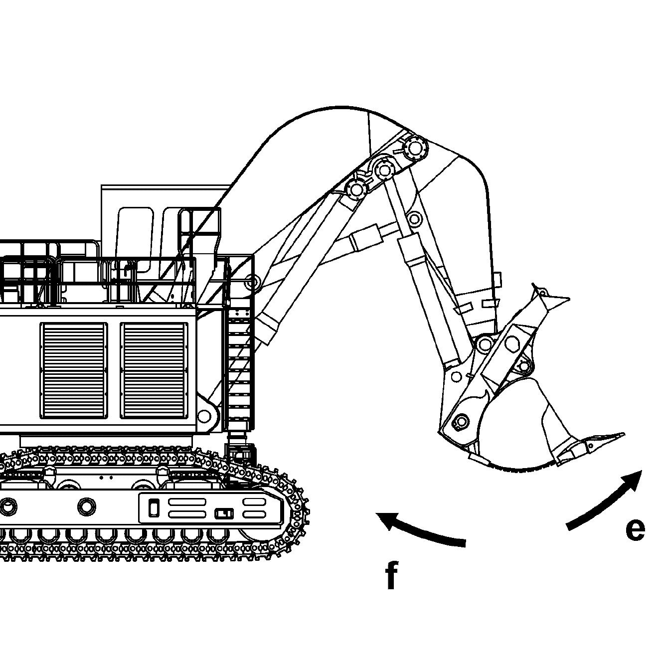
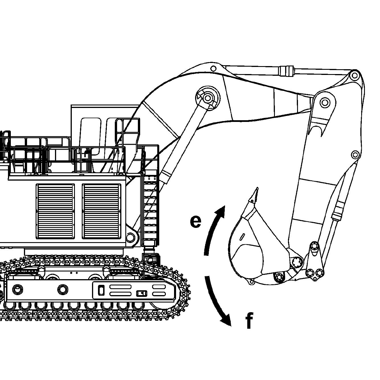
Operating thebucket
The bucket cylinder is operated using the right joystick 3.
Push the joystick to the left e Bucket will be tilted inwards. Push the joystick to the right f Bucket will be tilted outwards.
The bottom dump shovel bucket is moved via two pedals, 7a and 7b.
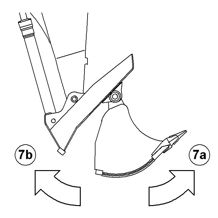
Push pedal 7a. Shovel bucket will be opened. Push pedal 7b Shovel bucket will be closed.
Floatpositionofboomcylinderforbucketoperation(optional equipment)
Position
To turn on the float position for the lift cylinders, Move the right joystick 3 forward, Push the button S5 on top of the handle at the same time.
Now the bucket can be used for grabing work while moving the joystick 4 forward to extend the crowd cylinders.
Theattachmentcanthenmovefreelyupordowndependingongradeandthebucket will automatically follow the ground contour.
Combined movements
Movingajoystickdiagonallyresultsintheworkfunctionsconcernedbeingcombined. This allows different equipment movements to be activated at the same time. The operator can do the following movements without any additional manipulations. When the swing movement is actuated, all working functions / movements are possible without affecting the swing movement.
Duringtravel, every attachment movement is possible,but theswingmovementhas priority. In this case, the travel movement is reduced.
3.4.4Loweringtheworkequipmentwhenthemotorisnotrunning
In an emergency, the equipment can be lowered when the electric motor is not running.
Fig. 3-71 Lowering the equipment when motor is not running
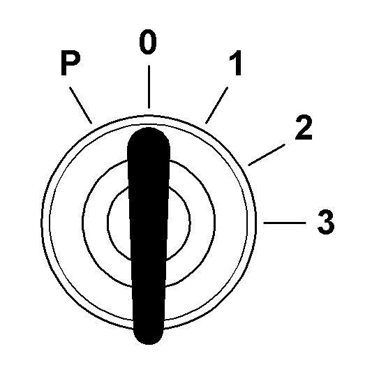
Turn the ignition key to contact position 1
Operate the joystick or the foot pedals until the equipment has lowered.
Note
Thisreserveislimitedandisonlysufficientforsmallmovementsofthepilotcontrol devices.
Only operate the joystick in the directions for lowering the equipment.
3.5General working methods
3.5.1Minimum impact working methods for your machine
Toincreasethe servicelife of themachine andavoidunnecessary damage andthe resulting repairs, please note the following points: stopping the equipment on the walls of the ditch. the equipment is knocked against the materialtoberemoved,inthelongitudinaldirectiontoo,isnotpermitted.Repeatedly hitting the work equipment against rock or other hard material will damage steel parts and machine components. andworktool,theworktoolcouldhitor operator. in rocky material. This will extend the work cycles and could result in damage to the bucket and other machine components. l partner if special teeth are required for heavy or special applications. thisshouldoccur,slowlylowerthemachineto the ground. Do not permit the machine tolower quickly and do not intercept the falling movement using the hydraulics,since this couldresultin damage to the machine.
3.5.2Preparatory activities
Danger!
Risk of fatal injury and damage to the machine when working. erating instructions.
Position the machine so that the load material can be taken up above the idler.
Danger!
Insufficient support and machine damage.
Danger!
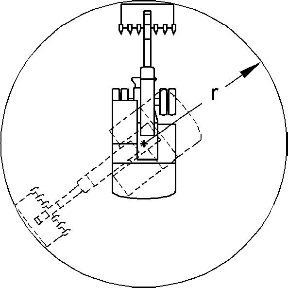
Risk of fatal injury due to rotating the machine. Ensure that nobody stands within the hazard area r of the machine.
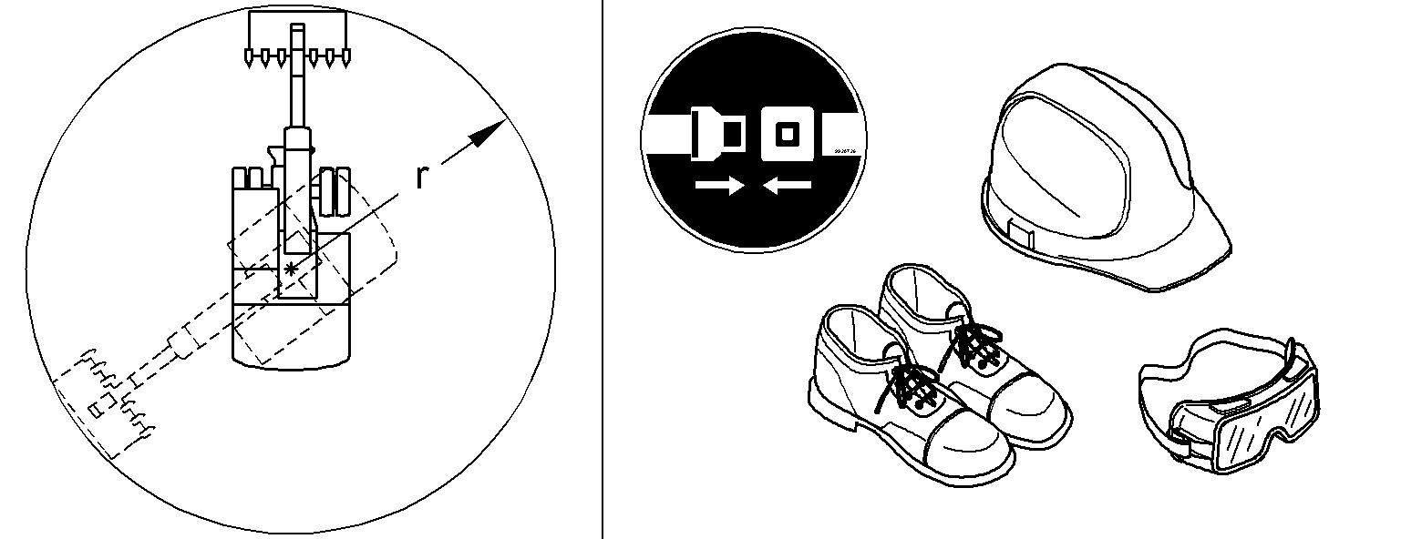
Caution!
Risk of injury when working.
Always wear safety shoes and, particularly when leaving the cab when demolition work is going on, a protective helmet and safety glasses.
Always wear the seat belt. Use the horn to give a short warning signal before starting work.
3.5.3Positioning of the machine
Settingupproperlyisapre-requisitetosafeefficientloading,andhelpsmaintainstability,power andbenchlevels.It will alsoreduceoperator fatigue.Positionthe excavator as close to the working face as safety permits.
Caution!
Always ensure there is sufficient clearance between the counterweight and the face, including allowing for any rocks or material that may fall down.
The recommended digging range is about a 90° arc in front of the machine (A).
Note!
Avoiddigging at right angles to the tracks.
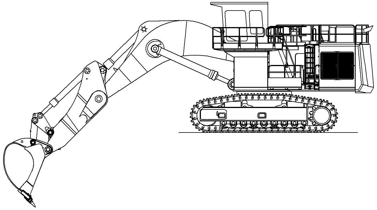
3.5.4Working with the backhoe bucket
Danger!
Risk of fatal injury and damage to the machine when moving the backhoe bucket. Ensure that the backhoe bucket is not slewed too close to the cab. tor.
Ensure that nobody is standing within the hazard area of the backhoe bucket.
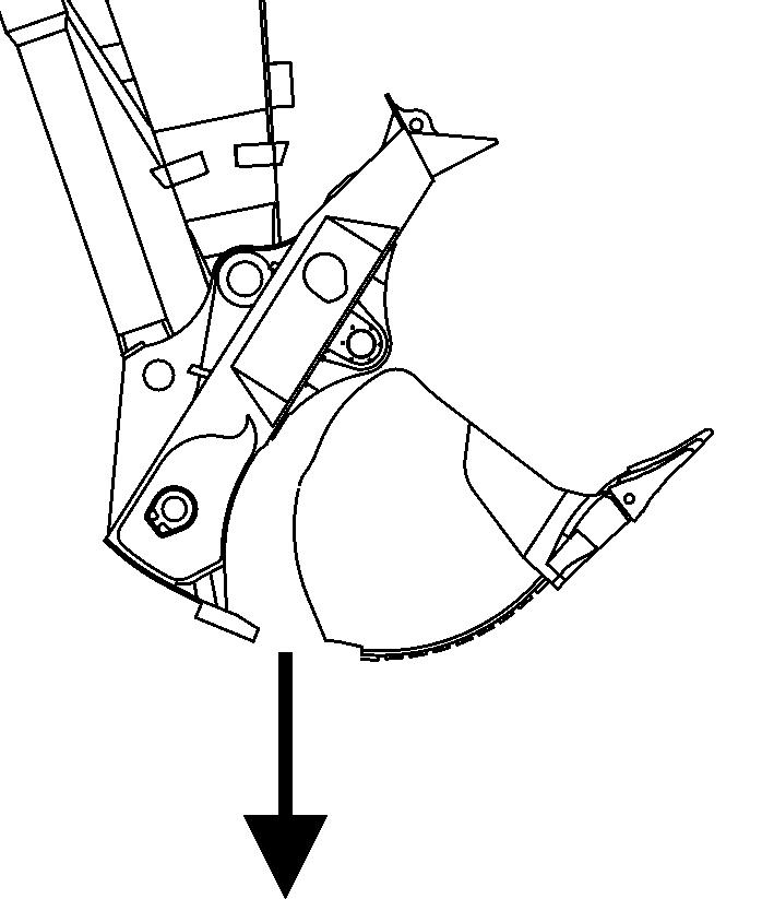
Aligntheshovelarminsuchawaythatitsundersideisatanangleofapprox.30° forward to the vertical.
Align the backhoe bucket in such a way that its underside can enter the ground at an angle with the axle of the shovel arm between 10° and 20°.
Taking up grab material
To lift out the grab material, slowly and evenly slew in the shovel arm.
Assoonastheshovelarmisatanangleofapprox.45° backwardtothevertical, raisetheboomslowlyandevenlyinadditiontoslewingintheshovelarmandthe backhoe bucket. Stopping suddenly will result in impact loads and vibrations. When the backhoe bucket is full or the shovel arm can no longer be slewed in, raise the boom and backhoe bucket until the filled surface is parallel to the ground.
Note!
Foraefficientdigging,thedepthofthe of the shovel arm.
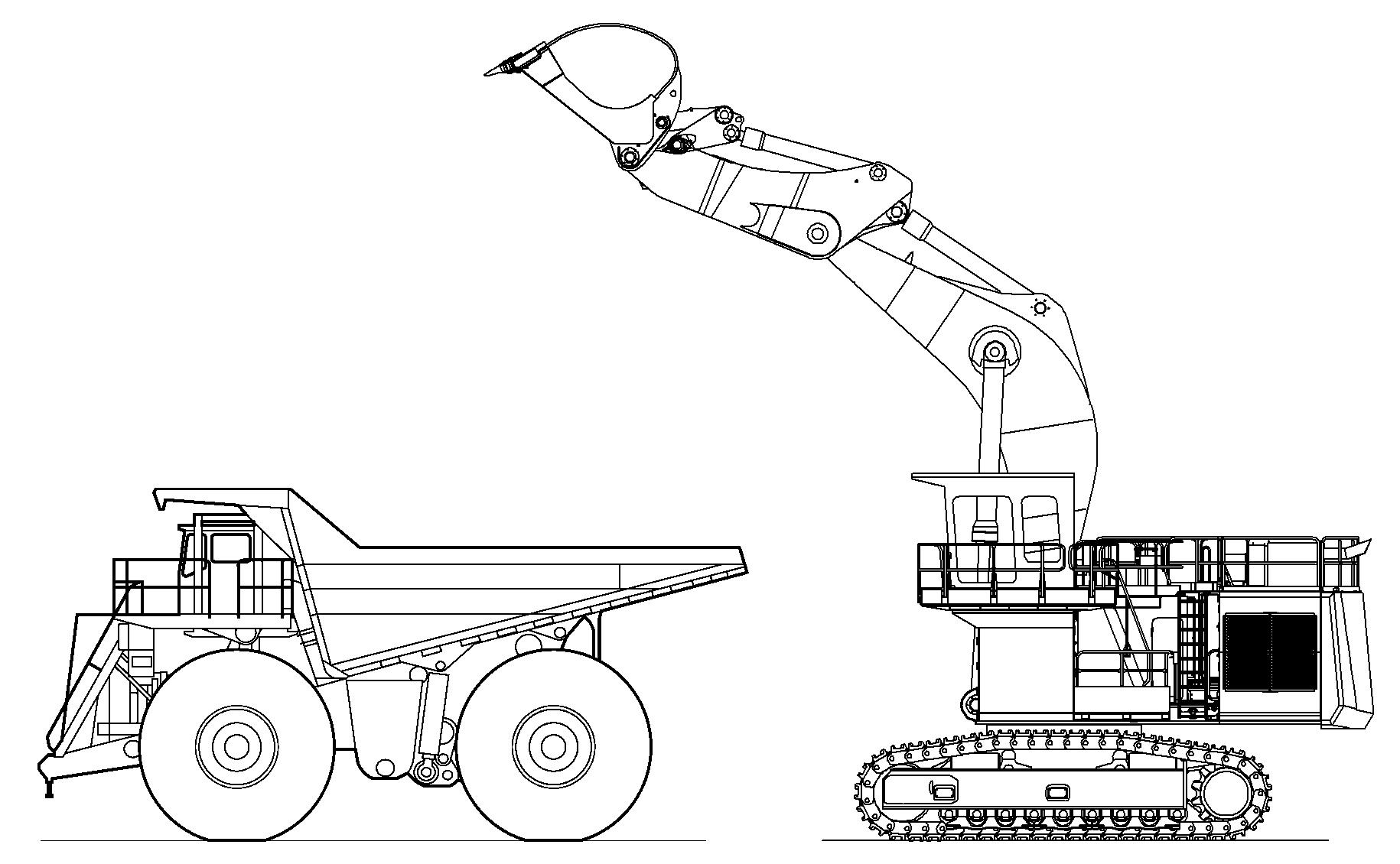
Loading the transport vehicle
Danger!
Risk of fatal injury due to falling grab material.
Do not load the transport vehicle so high that the grab material could drop out over the walls of the vehicle.
Ensure that nobody is standing in the danger.
Load anoccupied truck only if all safety requirementsarefulfilled, notably inorder to protect the truck operator.
3-79 Emptying grab material
If possible, the machine should stand higher than the transport vehicle to avoid having to lift the grab material unnecessarily.
Stopthetransportvehicleinapositionthatallowsittobeloadedfromtherearor the side.
Slew the machine's equipment above the loading area of the transport vehicle. Distribute the grab material evenly over the loading area of thetransport vehicle by slewing the backhoe bucket and shovel arm out, slewing the upper carriage and possibly also moving the boom.
Ifthebackhoebucketisnotsufficientlyemptiedorthereisstillgrabmaterialinthe backhoe bucket, slew thebackhoebucketin andout several times to loosenthe grab material.
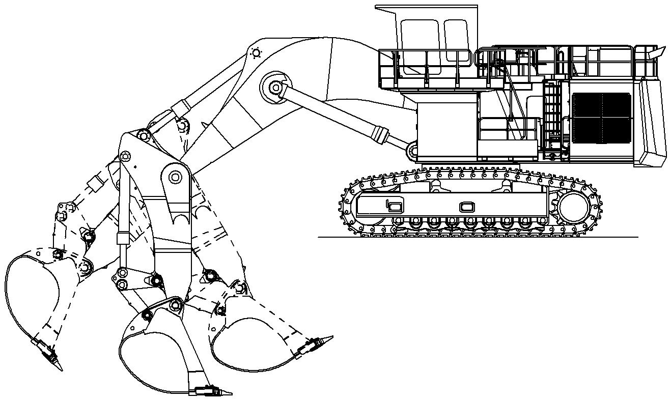
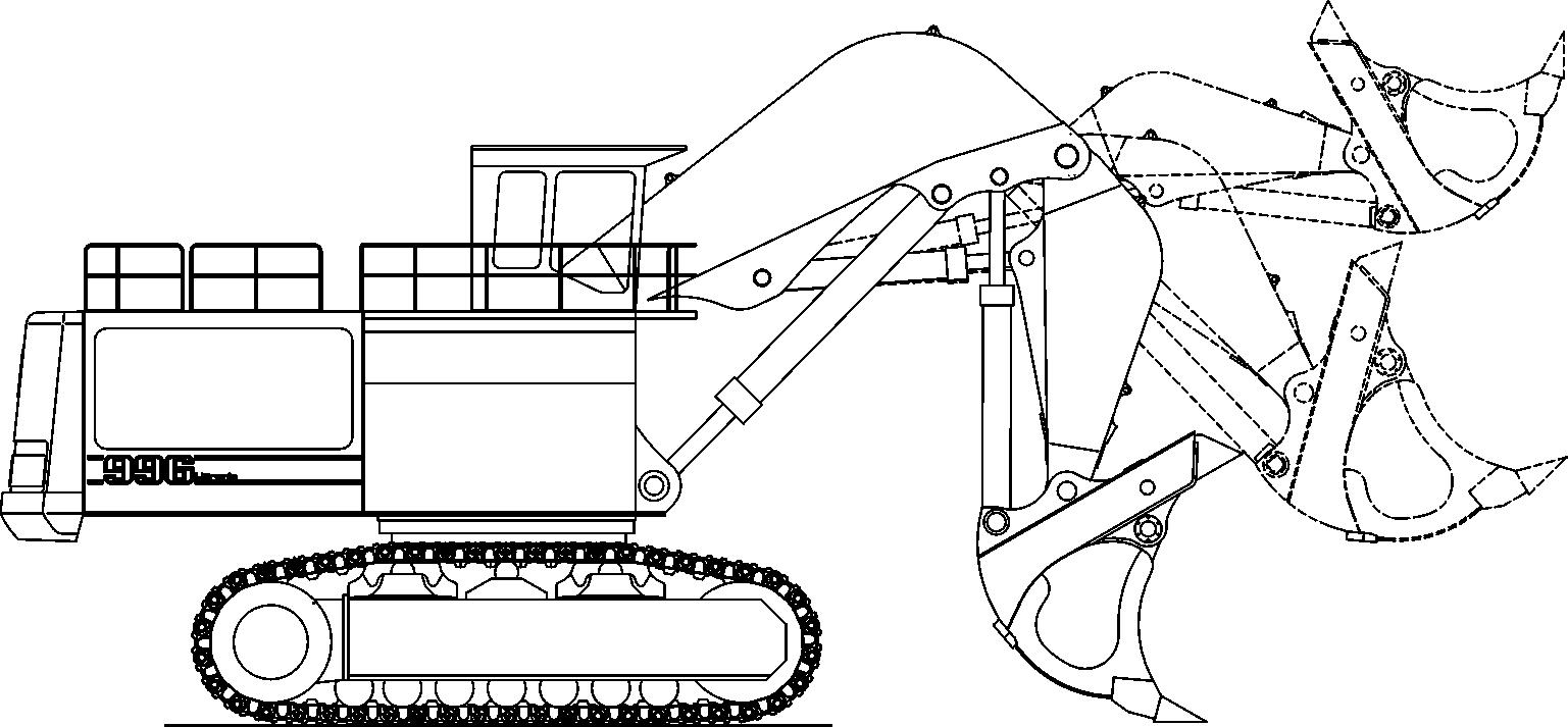
3.5.5Working with the Shovel bucket Digging
Tomaximisemachinepowerandbreakout,maintaingradeandfillthebucket,correct digging angles and technique should be used.
3-80 Digging
Mostdiggingshouldbestartedwiththebucketalmostfullycrowdedback(50mm off stops or end of cylinders).
When cleaning up or digging at floor level, angle the teeth aggressively to break out any toe that may be encountered.
Keepingtheheel ofthebucketoffthegroundthereforecreatingavoidunderthe rear of the bucket.
Operate with the teeth and bucket lip doing all the work.
Note!
Avoiddigging at right angles to the tracks.
Caution!
Eachtimethe stick is crowded back tocommencea cut, extreme caution must be taken not to hit the tracks.
The clam must always be closed when di Avoid working on the cylinder limits and bucket stops during the digging cycle. Continual use of these practises will lead to premature failure of seals and Orings andcan causestress fractures totheclam, stickand bucket and damage to the boom and superstructure.
Crowd the bucket in (down) while closing the clam. This practise makes use of gravity to help minimise shock loading on the bucket cylinders.
Neverdig,orattempttobringdownanymaterialoverhang,withthebucketwhile the clam is open or partly open.
Do not attempt to dig or clean the floor or face with the clam open. These practises can cause considerable damage to the clam cylinders.
Unload the bucket
Fig. 3-81 Unloading of the bucket
Whendumpingtheload,tipthebucketforwardslightlyastheclamopens.Thishelps direct the material to fall centrally into the tray and avoids spillage.
Thepositionofthebucket backboardwhentheclam opens,directlyaffectstheposition of the load in the tray.
Bucket in ideal position resulting in material falling straight down. Loading centre of the haul truck.
3.6Transport
3.6.1Travelling procedures for mining machine
Thelifeexpectancyofundercarriagecomponentsisbasedonstandardworkingconditions with a maximum travel ratio of 5% per service meter unit. Working and / or travelling on uneven ground and / or abrasive material will influence the lifetime of the components and attract additional cost for the undercarriage components.
Downhilloruphilltravelonaslopehasalsoaneffectonthelifeexpectancyofundercarriagecomponentsandontheirwearrate.Indeed,eveniftheslopeangleisbelow the maximum permitted travelling angle, the increase of the slope angle causes the increase of the force and of the contact pressures applied on all track components (trackpadassembly,sprocket,...).Onanindicativebasis,thetravelforceappliedon thetrackcomponentsismultipliedbytwofromaslopeangleof5°(8,7%)andismultiplied by 2,5 from a slope angle of 10° (17,6%).
In general travel action has to be kept to the lowest level that is possible. Minimize travelling with turning through a narrow turning circle and long distance travel.
To minimize the travel ratio, professional mine planning with longfront winning sectionsispreferred.Ifdiggingoperationsatvariousspotsarenecessary,apropershort termandlongtermplanofwinningoperations hastobeemployedtoguaranteelong term use of the excavator at one place before moving to another location.
However, if frequent machine movement is necessary, the following set of procedures defined by Liebherr to minimize possible machine damage, downtime and wear have to be taken into consideration.
General
In order to move themachineforwards: withthe excavator instandardforward position, depress travel pedals all the way forward with the toes. Direction of travel is in the direction of idlers.
Inordertomovethemachinebackwards:withtheexcavatorinstandardforwardposition, depress travel pedals all the way down with the heels. Direction of travel is in direction of the drive sprockets.
Moving the machine during loading operations
Moving the machine during loading operations means adjustment of excavator digging and / or truck loading position of some meters.
Important procedures: position as close as possible to the excavator undercarriage. counter turning the undercarriage, is not allowed,because it couldcausepremature structural damage to the machine. thetrackswherethemachinewillnotturn, youmust move the machine several meters forwards and / or backwards and attempt to turn again. inturningthetracks,i.e.ifturningtotheright,swingupperdecktotheleftandvice versa.
Walking the machineover distance
Fig. 3-82 Hazard area r
Walking the machine distances means any movement of the machine of more than 100 m or for a time period longer than 3 minutes, whatever comes first.
Inadditiontoabovementionedguidelines,whenmovingthemachineduringloading operations, the following procedures apply: eanall very dirty parts of the undercarriage and remove the unwanted materials. ature of the drive components, including the track and carrier rollers.
Danger!
Duringthemovementofthemachine,thepersonwhichischeckingthetemperature of the different rollers must always be out of the hazard area r of the machine and t and in radio contact with him.
For the checking of the temperature, the excavator should stop moving. And only when the excavator is stopped, the person could go in the hazard area r to check the temperature of the different rollers. The machinecould only start moving againwhen the driver has seen the operator out of the hazardarea r growing up about 20°C above ambient temperature, interrupt travel and only commence again after parts have sufficiently cooled. tospeedupcoolingprocedureitisadvisable to have a water truck standby, to hose the heating components during travelling or coolingbreak. venewithminesafetyregulations,swingwhilsttravellingtoequallyloadtrackrollers. However, always ensure that clear forward vision is maintained.
Travelling the machine down grades or upgrades
Inadditiontoabovementionedguidelines,whenmovingthemachineduringloading operations or when walking the machine distances, the following procedures apply: opeandnotperpendicularto theslope,with the uppercarriage aligned with the undercarriage.
7° (10%), it would be better to walk themachinedownwiththetrackmotorfirst,i.e.themachineismovedbackwards. esmustbeattherearoftheexcavator.
indicatedinthe"Technical data" sectionofthis manual(machinemustbe ableto walk up unaided). When moving down the ramp never allow the machine to fall downontheattachment.Whenwalkinguptherampnever useattachmenttoassist the movement by pushing with the hydraulic power of the bucket, stick or boom.
Travelling the machine first time
The slide bearing (friction bearing) of the track rollers needs some time for runningin.Ifthebearingbecomeshotatanearlystageofmachinelife,thismaycauselubrication problems during further life. Therefore when travelling the machine the first time aside from all above mentioned guidelines it is strongly recommended to move carefully and at reduced speed.
Note!
Warrantymaybecomevoidiffailuretorecognizeandcomplywiththerecommended travel operating procedures, as outlined in this document, is noted.
3.6.2Excavator lifting and lashing operations
Danger!
For safety reasons, always consider the precautions given in this section.
Lifting precautions
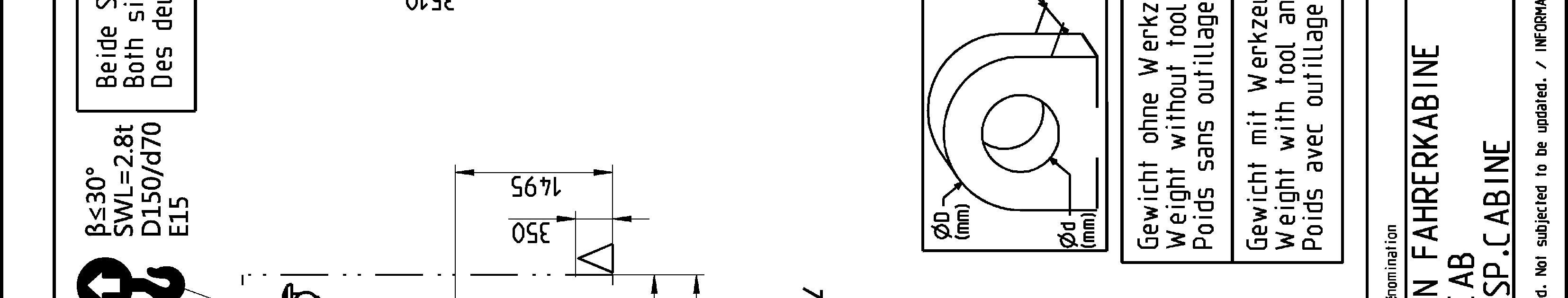
Lift element: sponding transport drawing, of other kind (cables, chains, slings) if necessary, es in accordance with the regulations, respecting the angles given on the sticker for lifting and lashing operations (refer to the description below).
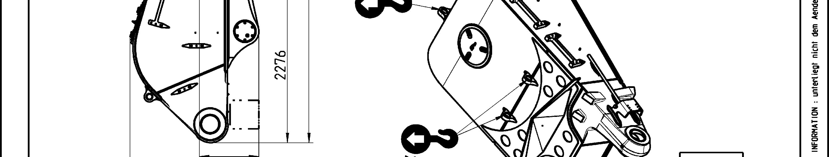
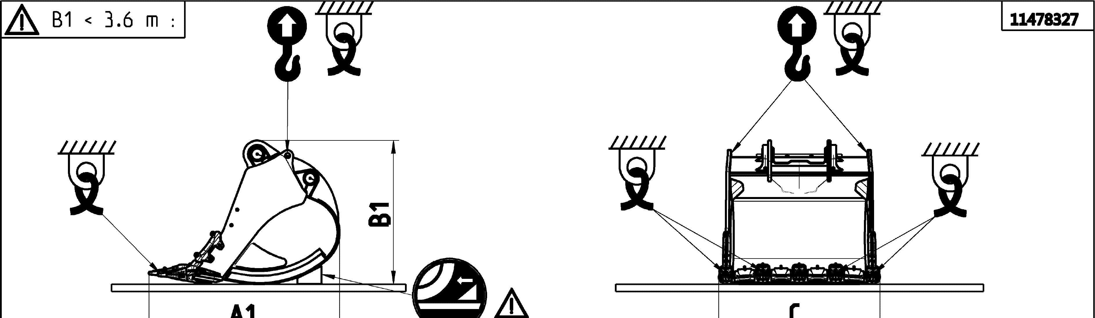
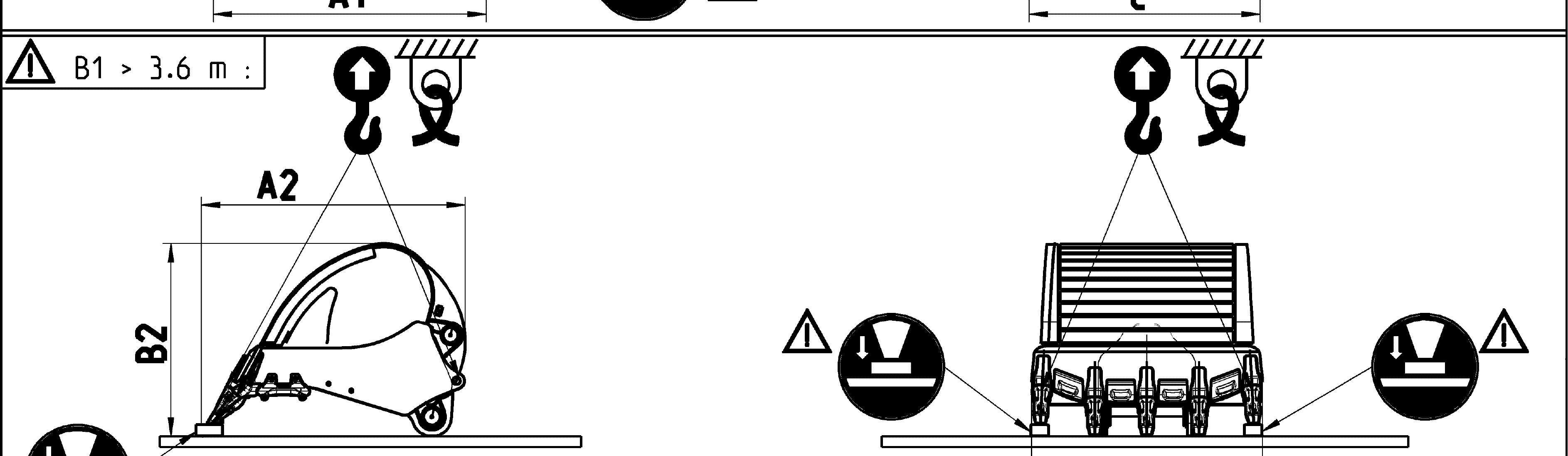
Additional lifting precautionsfor backhoe buckets e center of gravity of the bucket. transport position as shown in the transport drawing. 6 m, turn over the bucket safely.
When you lift the backhoe bucket, also obey the precautions that follow: the stickers placed on the bucket.
Additional lifting precautionsfor shovel buckets
When you lift the shovel bucket, also obey the precautions that follow: the stickers placed on the bucket.
Lashing precautions
Lash element: e center of gravity of the bucket. in order to ensure safe lashing, sponding transport drawing, respecting the angles given on the sticker for lifting and lashing operations (refer to the description below), supporting surface so as to avoid element to slip (e.g. using wooden parts, nonslip mats...), friction is guaranteed by manufacturer certificates, between each contact surface (e.g. between the load and the support, between the support and the flatbed trailer), actsurfacesbetweentheflatbedtrailerandtheload carried are free of dirt, ice, snow, oil and grease.
Additional lashing precautions for backhoe buckets
When you lash the backhoe bucket, also obey the precautions that follow: he center of gravity of the bucket. tions. The height B1 gives the correct transport position as shown in the transport drawing.
Additional lashing precautions for shovel buckets
When you lash the shovel bucket, also obey the precautions that follow: he center of gravity of the bucket.
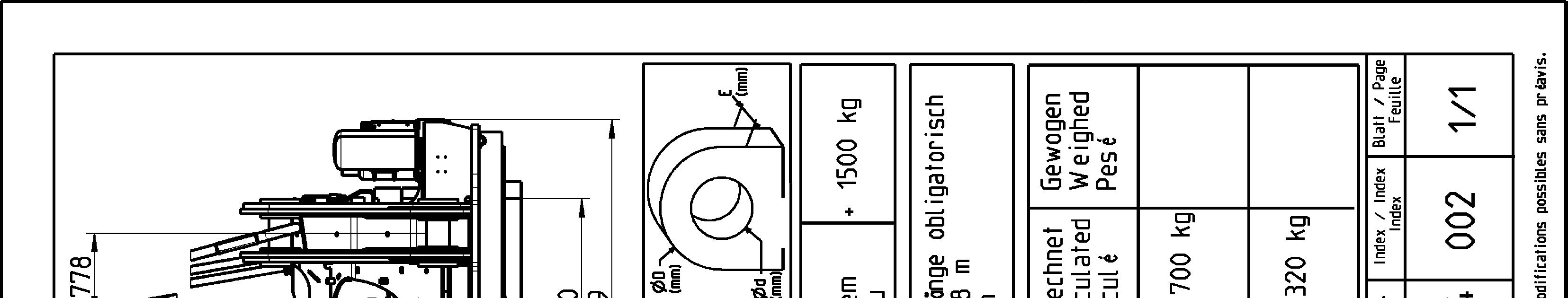
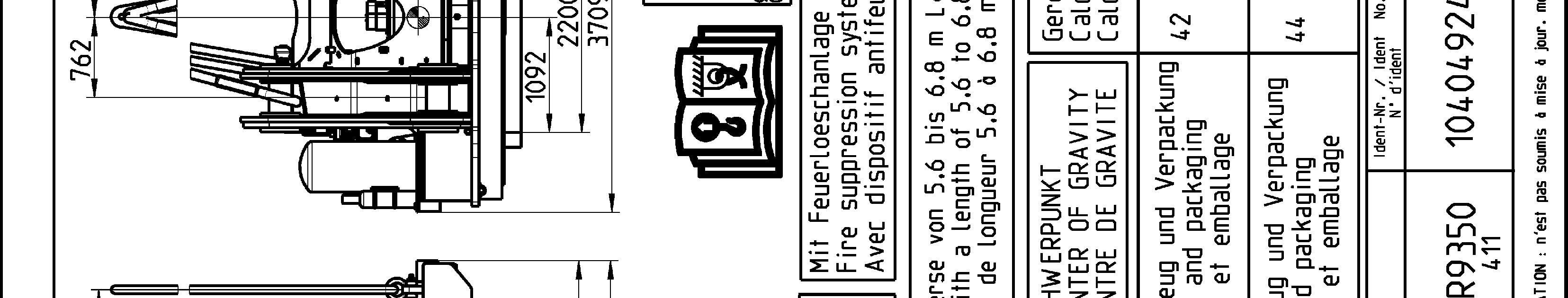
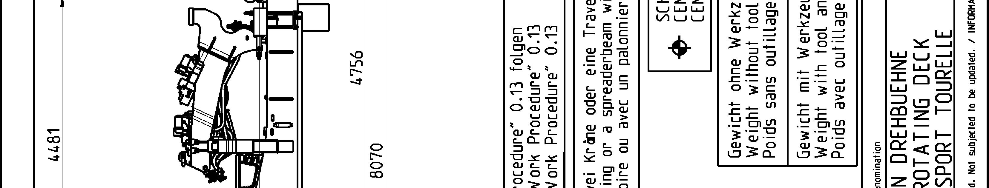
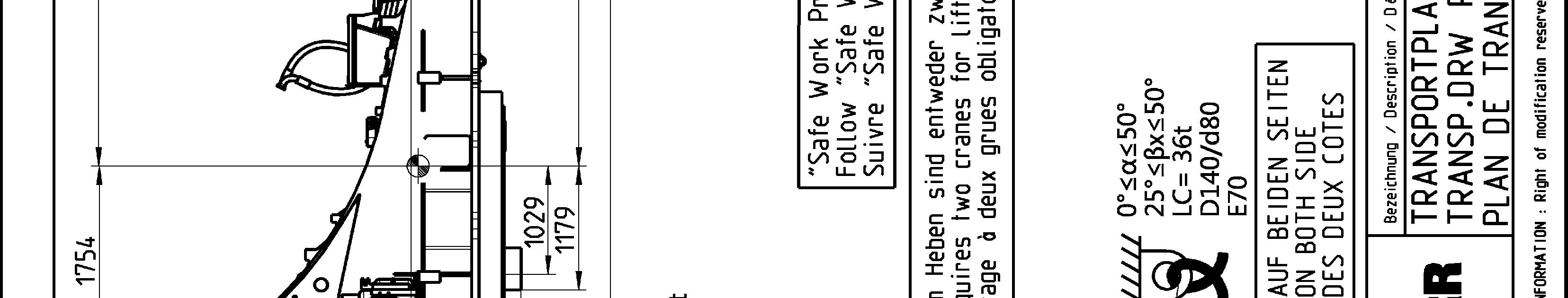
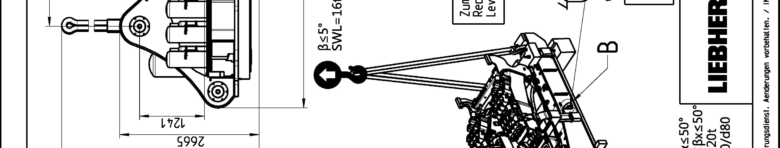
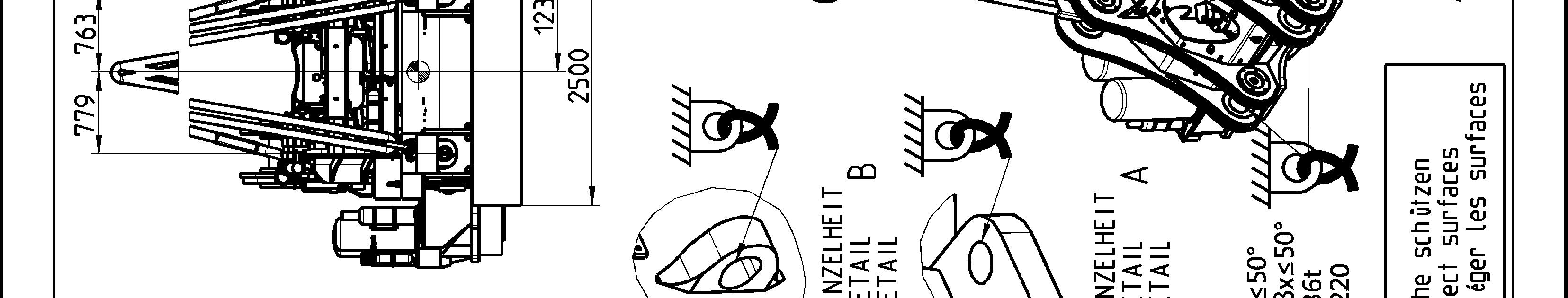
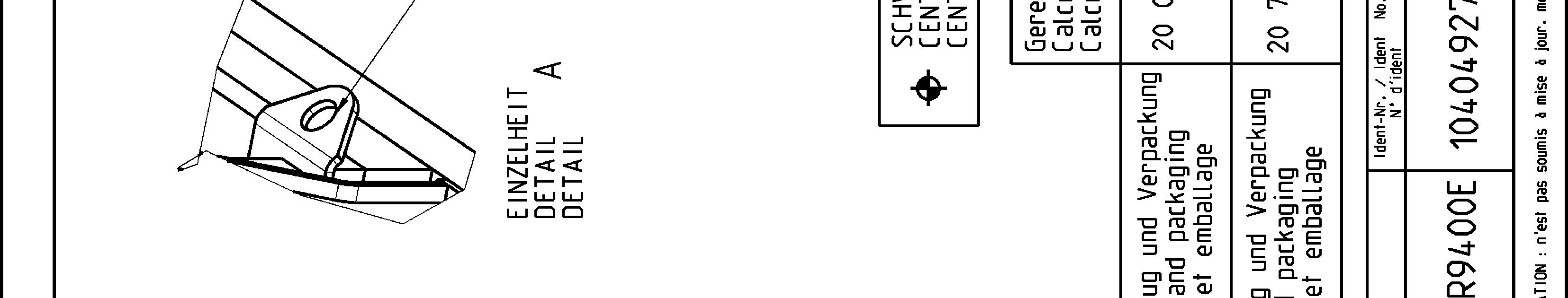
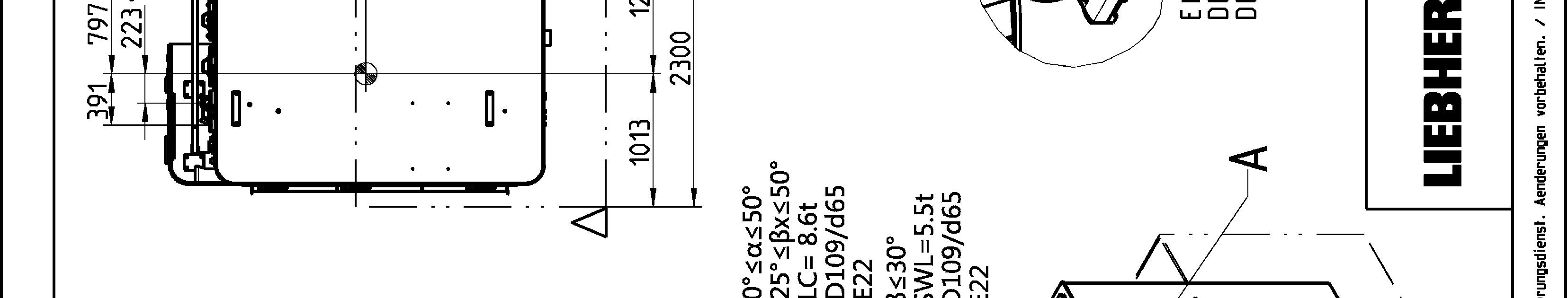
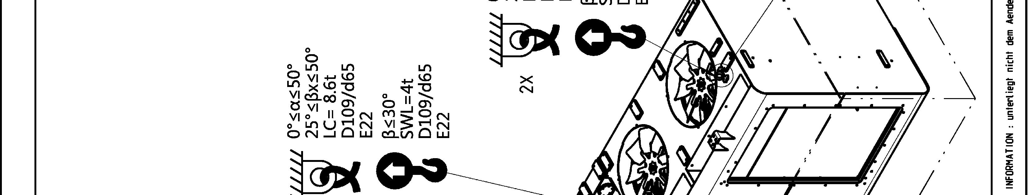
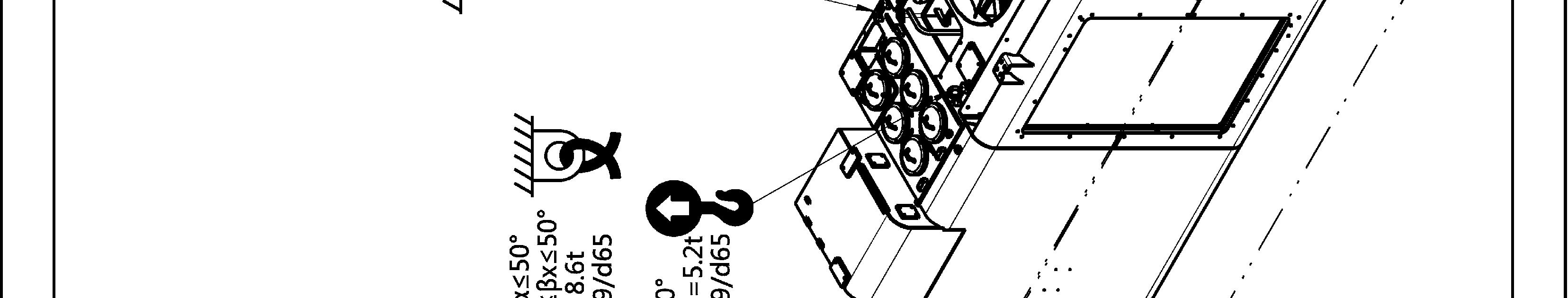
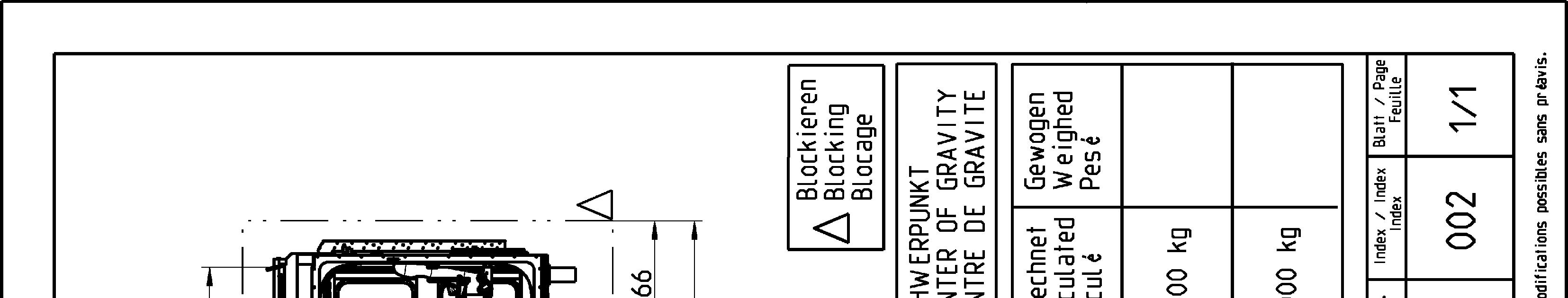
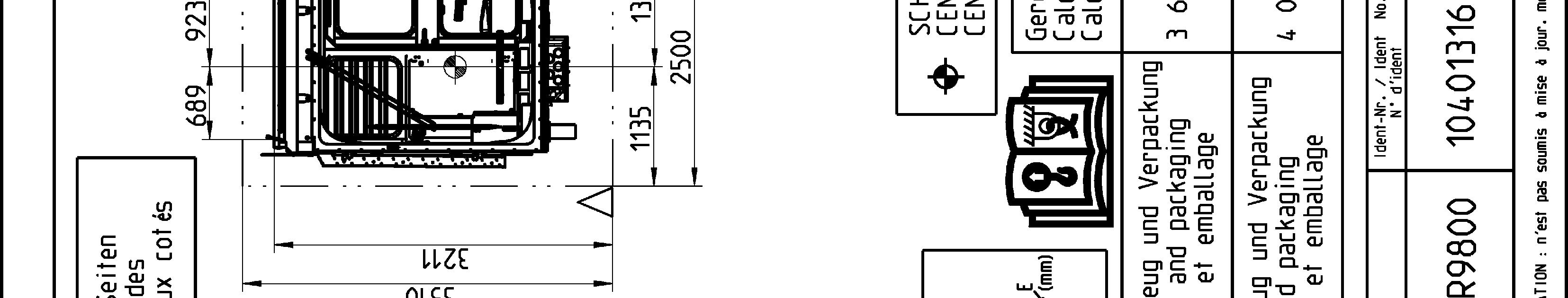
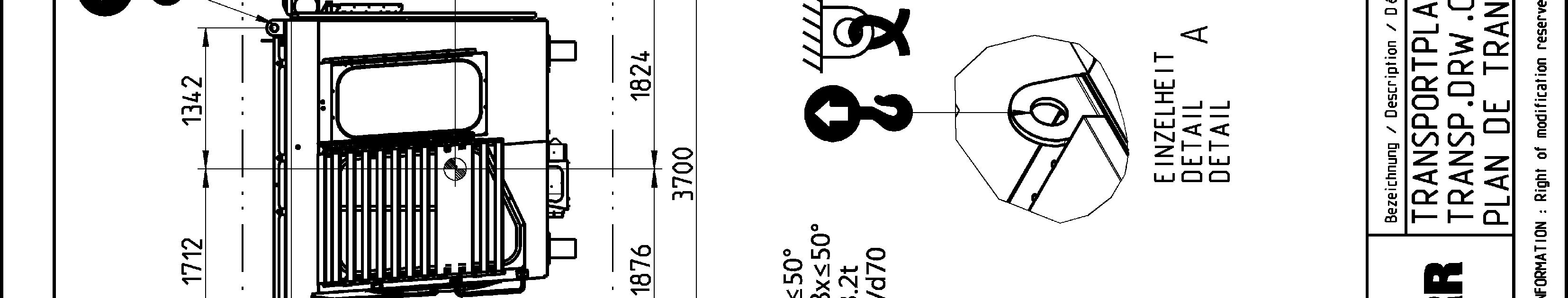
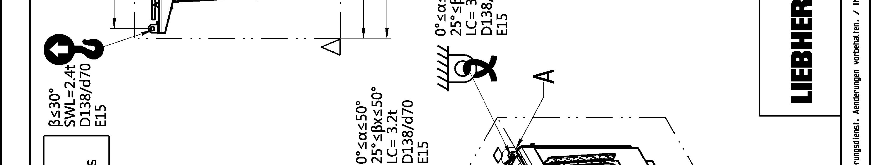
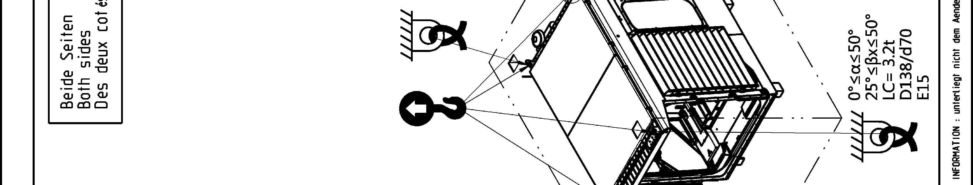
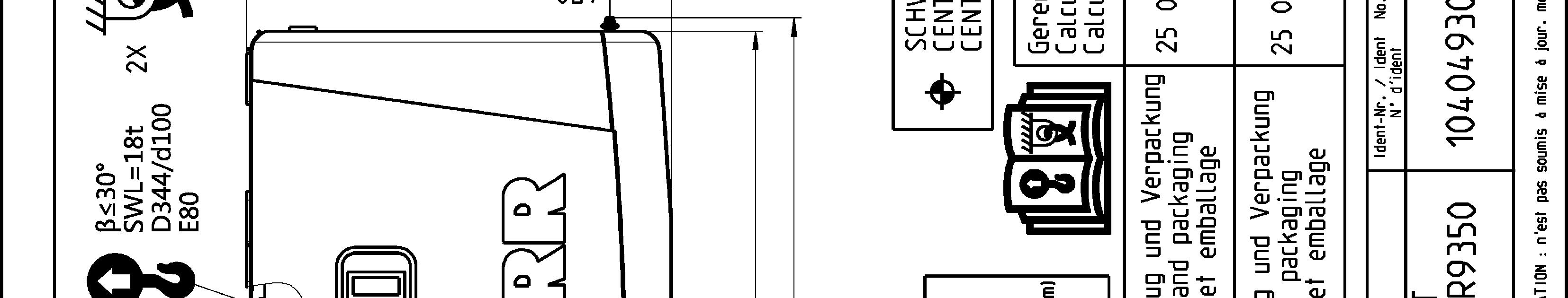
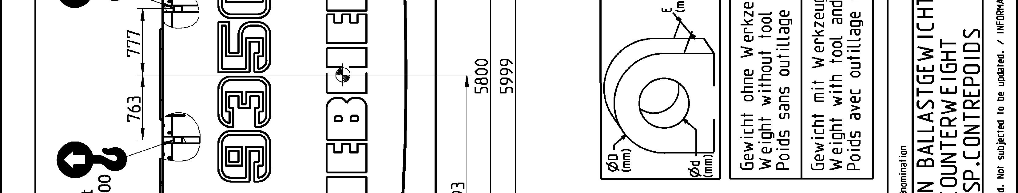
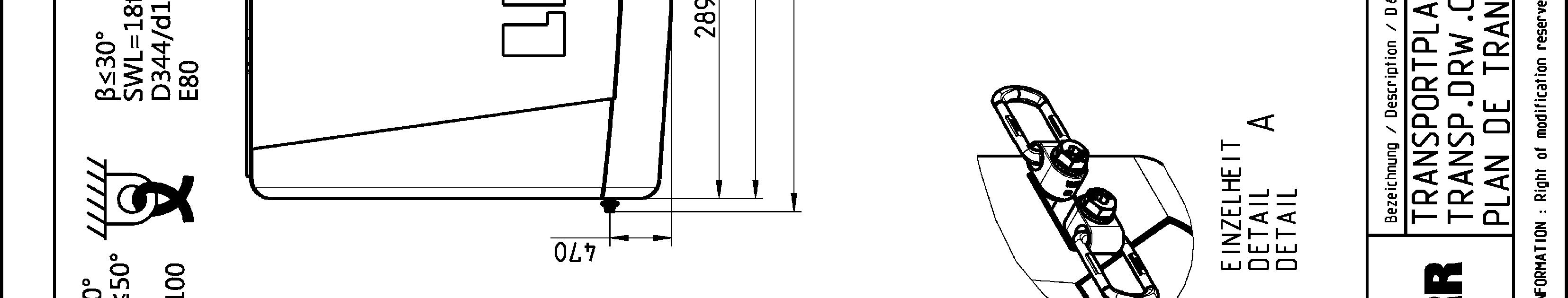
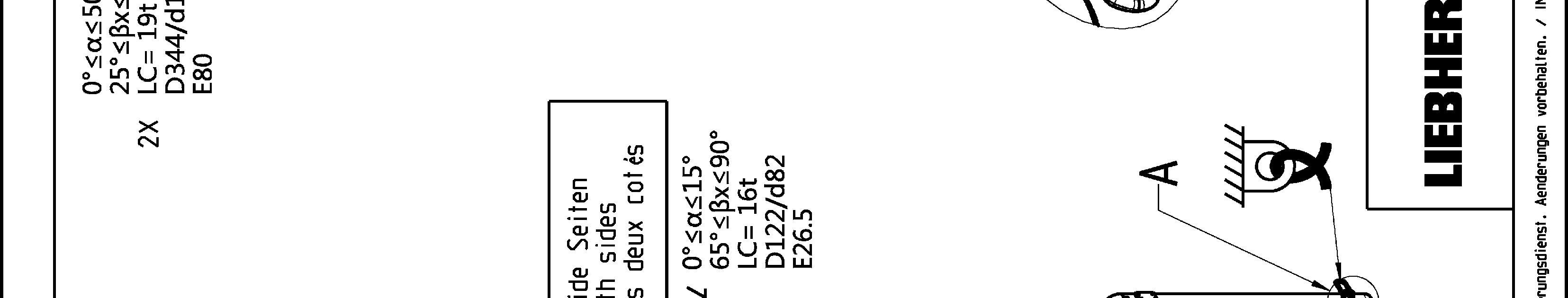
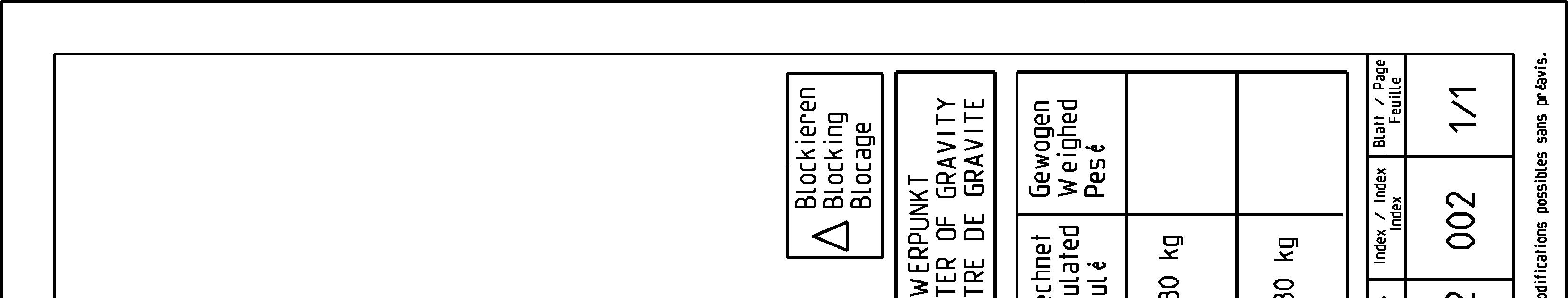
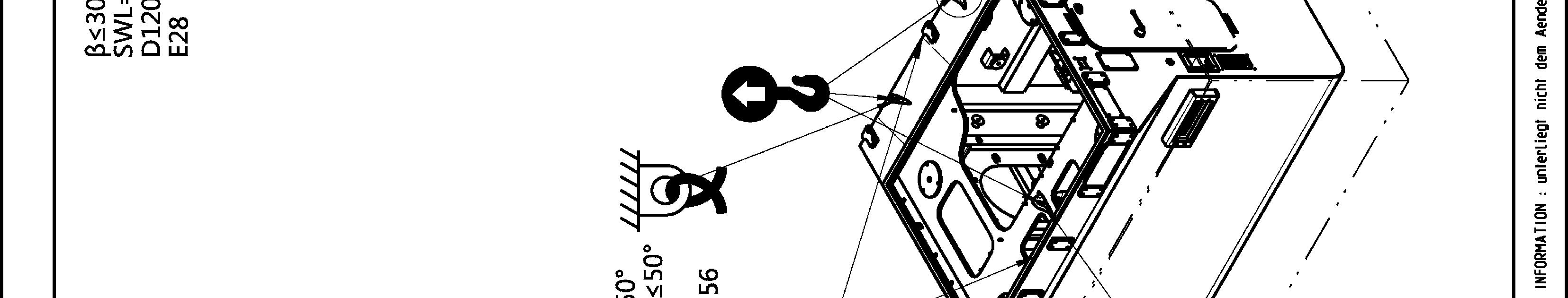
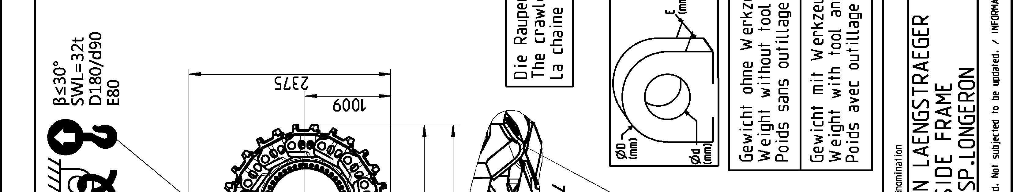
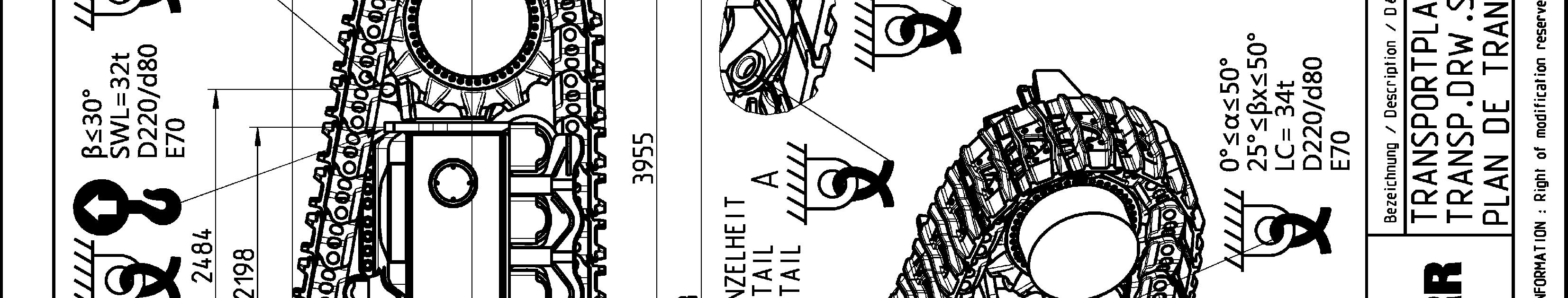
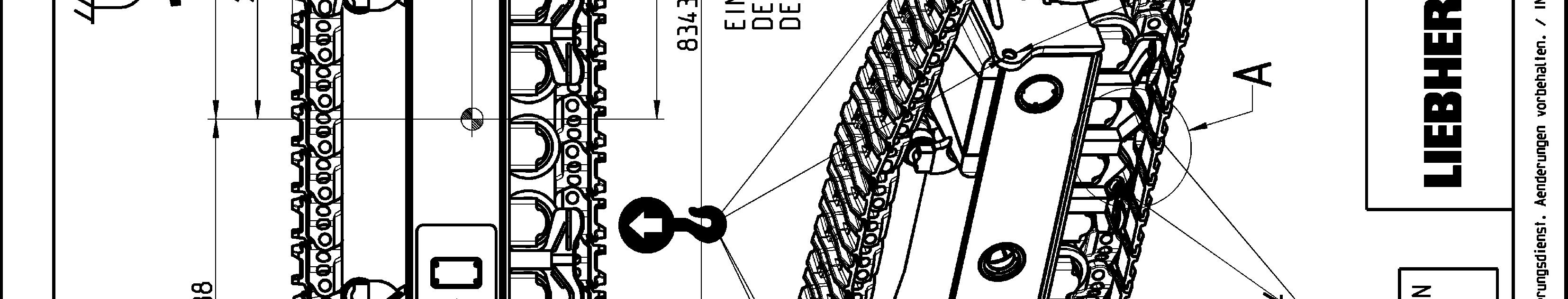
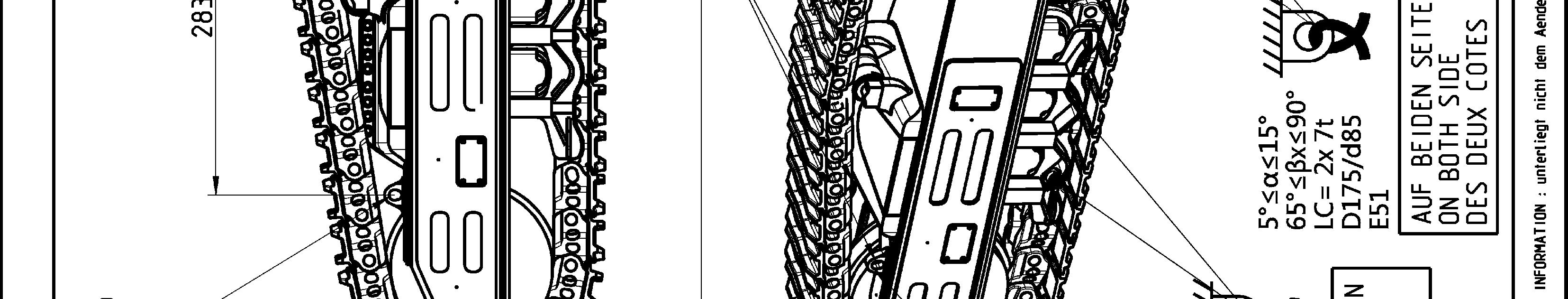
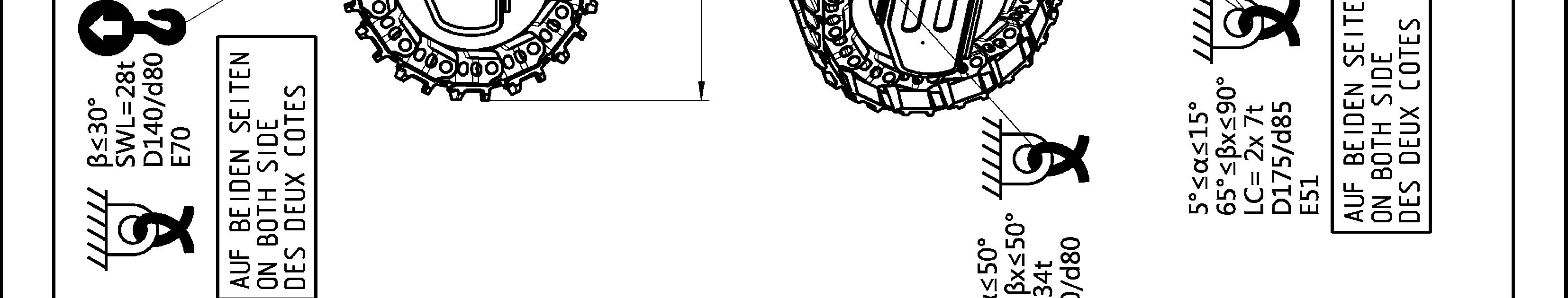
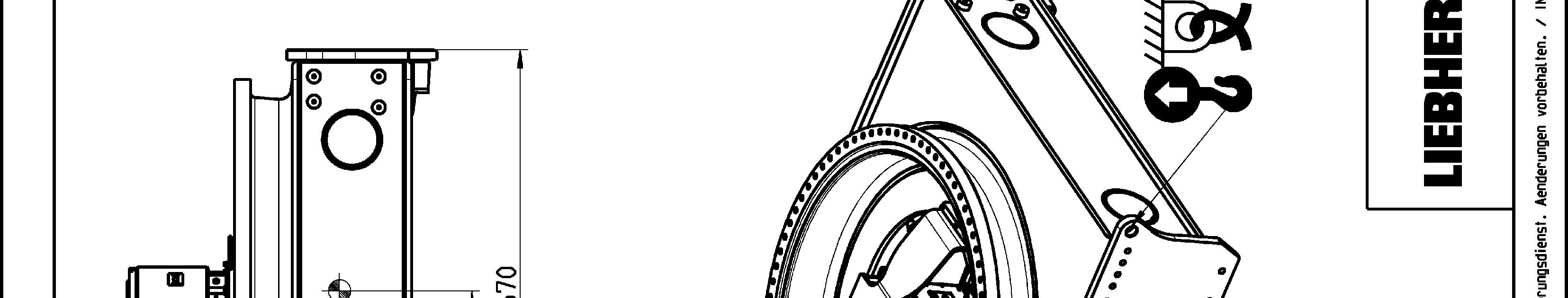
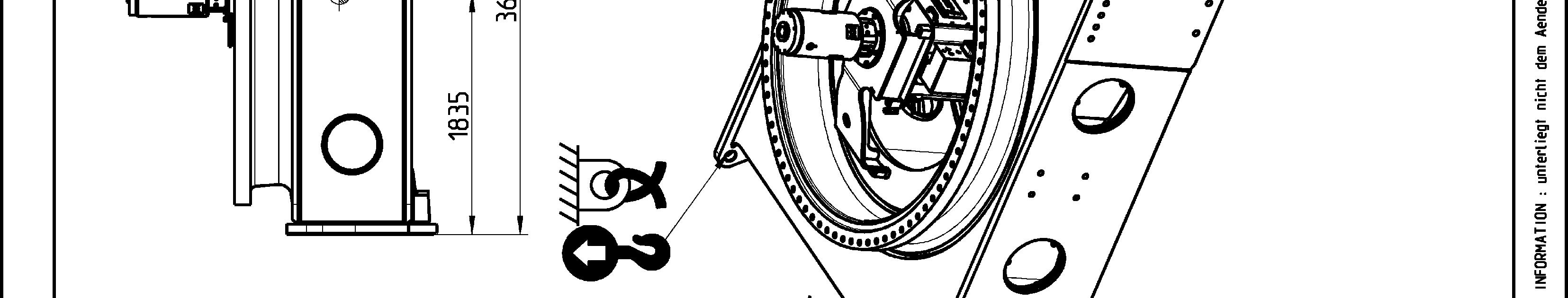
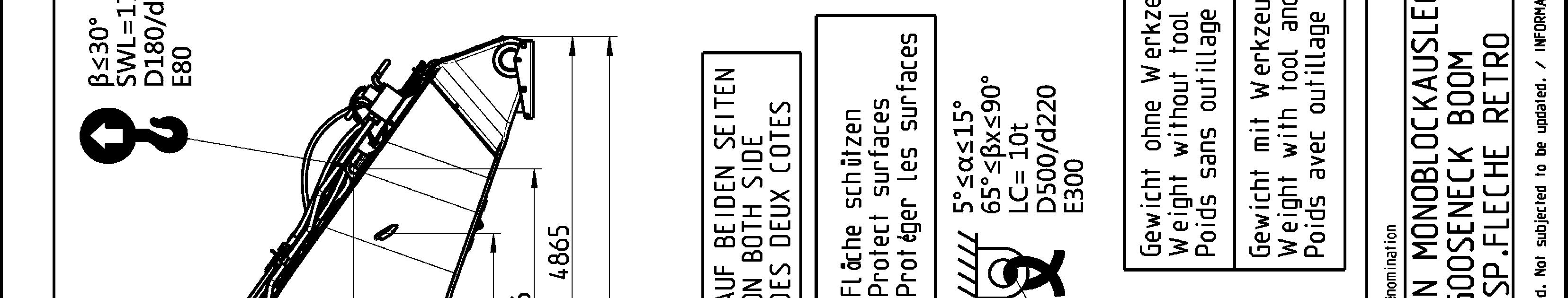
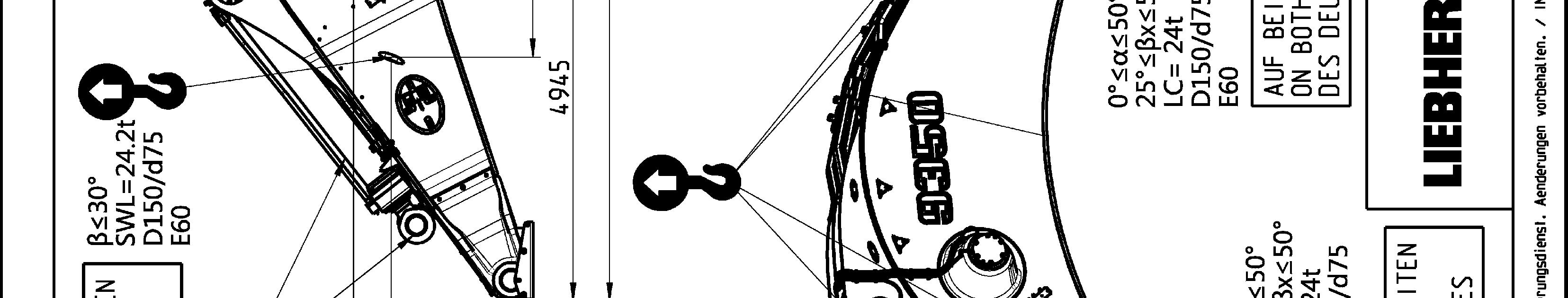
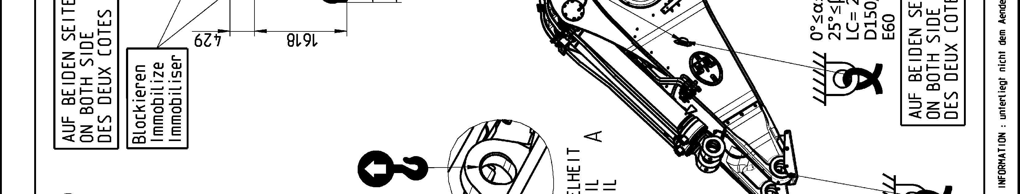
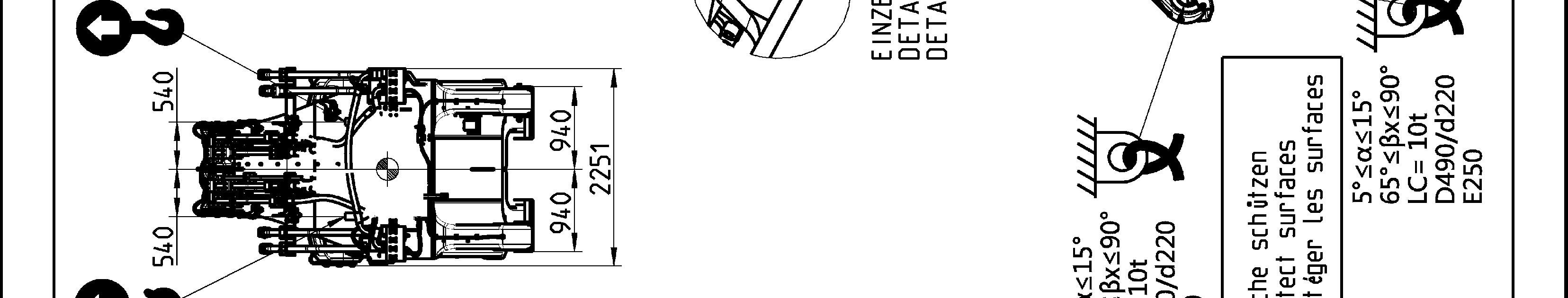
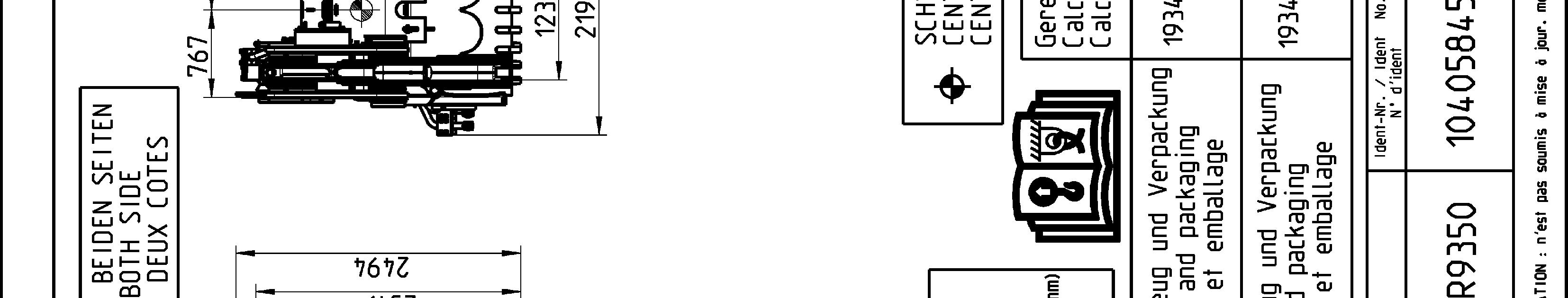
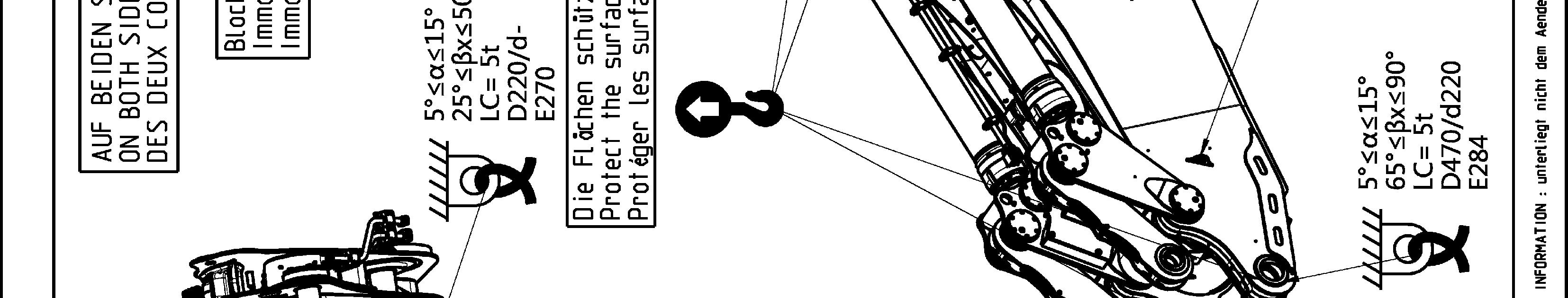
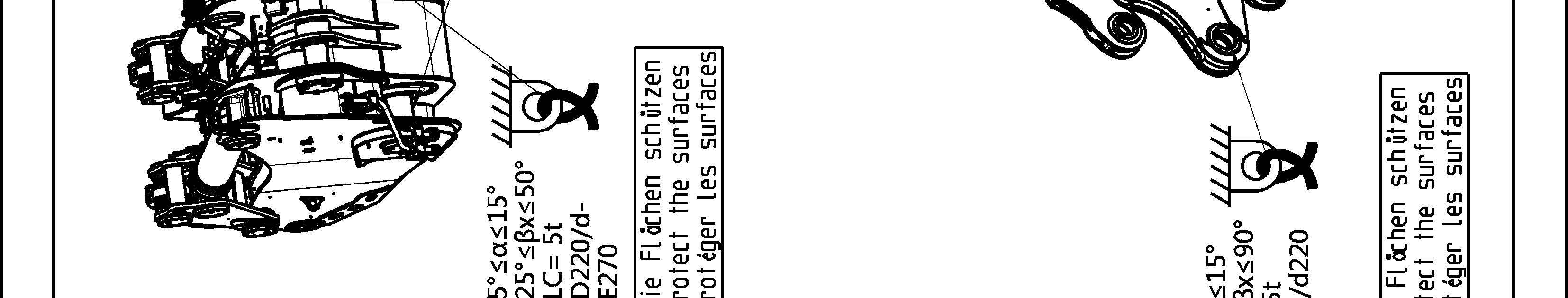
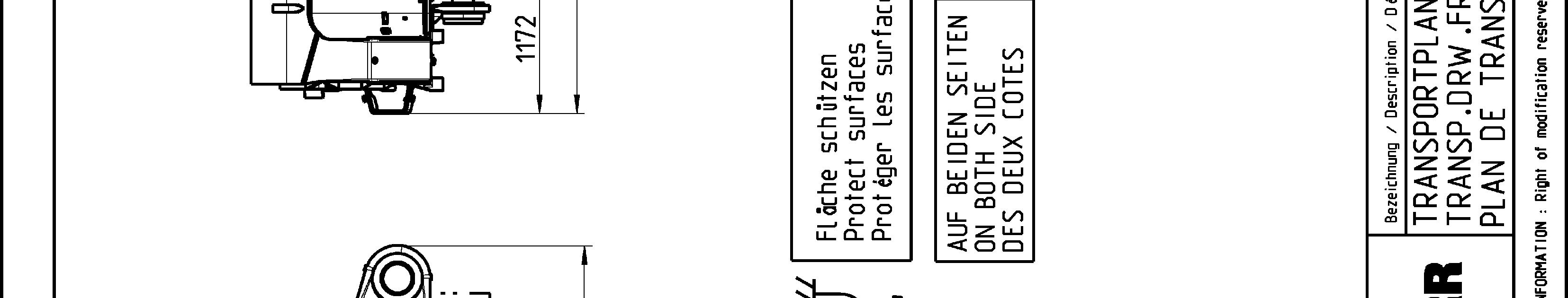
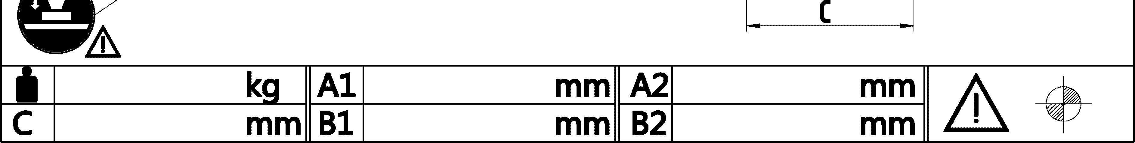
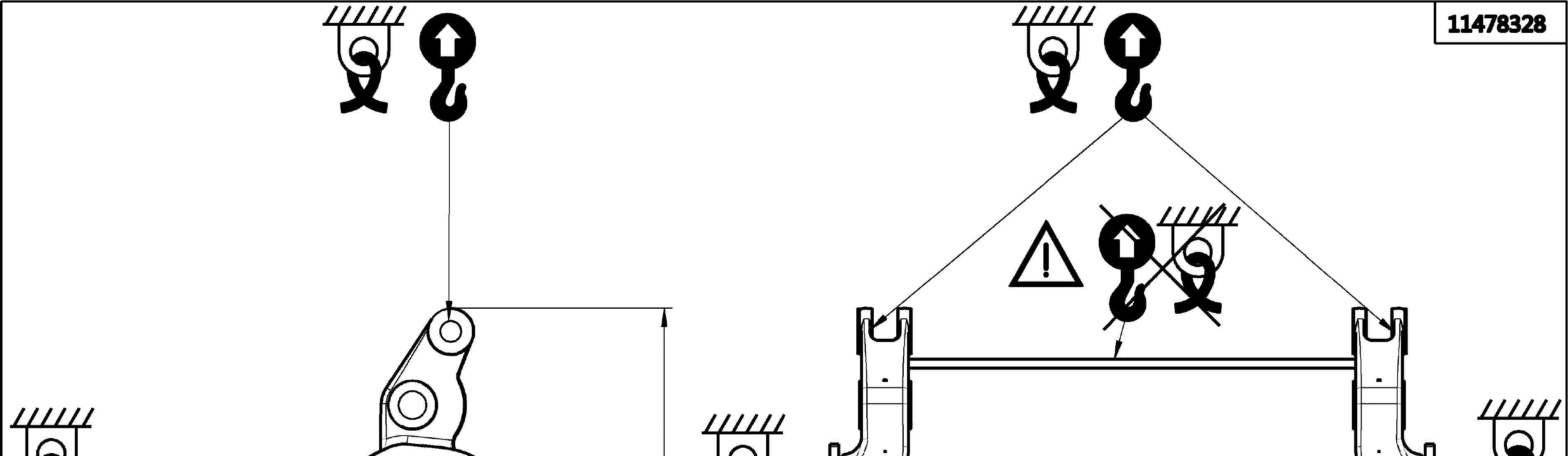
Sticker for lifting and lashing operations
Thefollowingstickerisplacednexttoeachtransportdrawingontherelatedpartand package. It shows rules and precautions which you must obey for transport operations.
Sticker for lifting and lashing operations
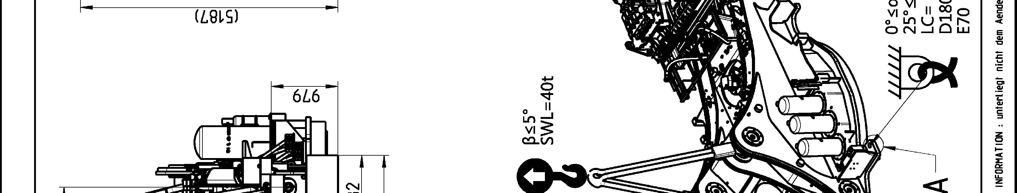
The Lashing Capacity LC is the maximum force that the lashing ring can hold in accordance with the angles given on the transport drawing.
TheSafeWorkingLoadSWListhemaximumloadthattheliftingringcanholdinaccordance with the angles given on the transport drawing.
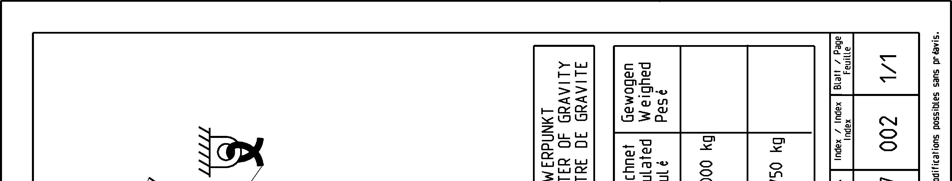
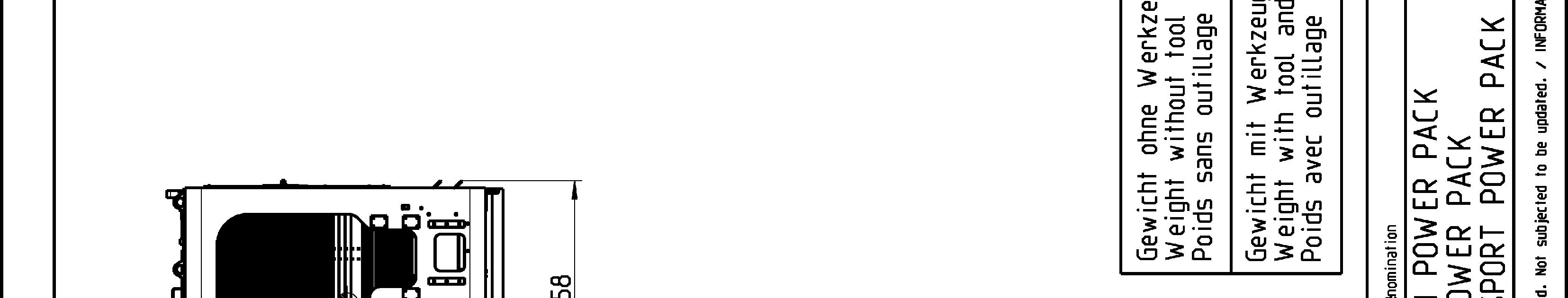
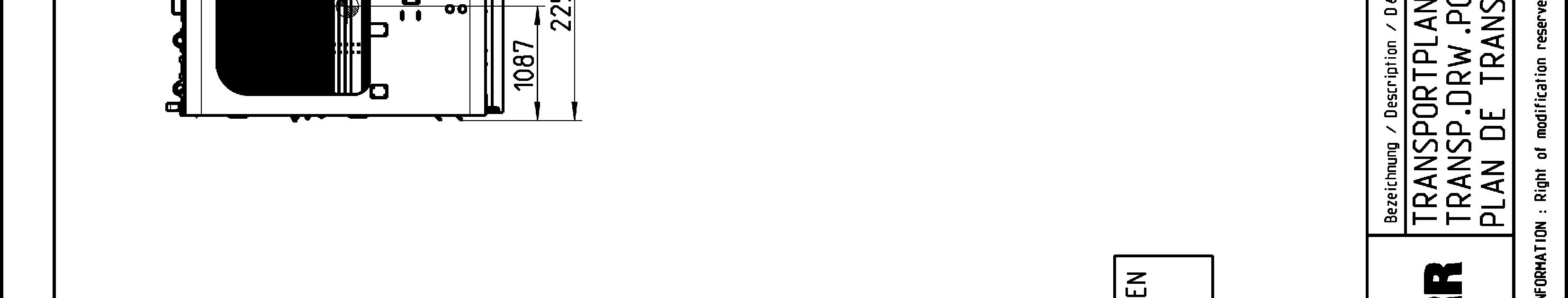
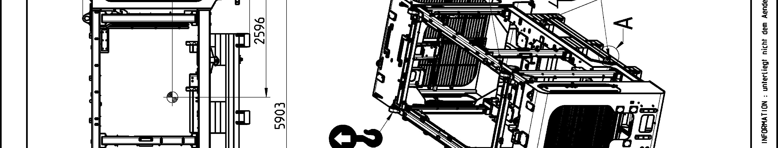
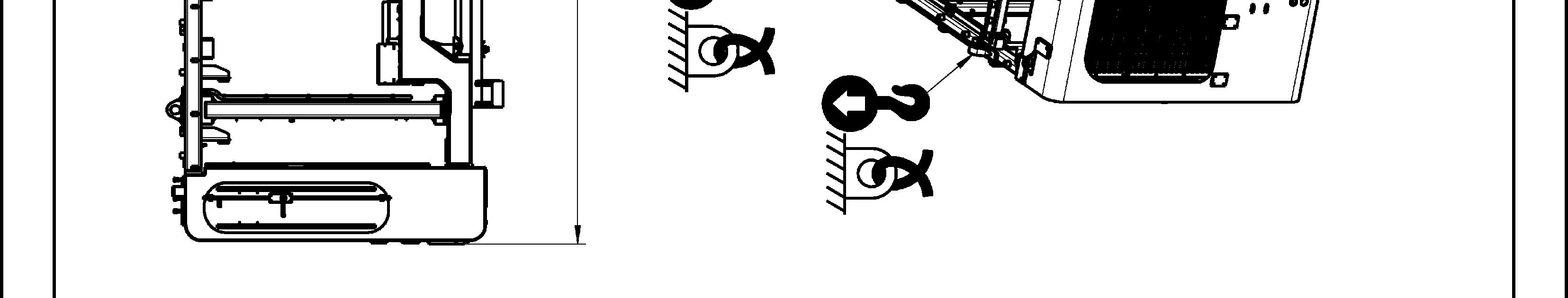
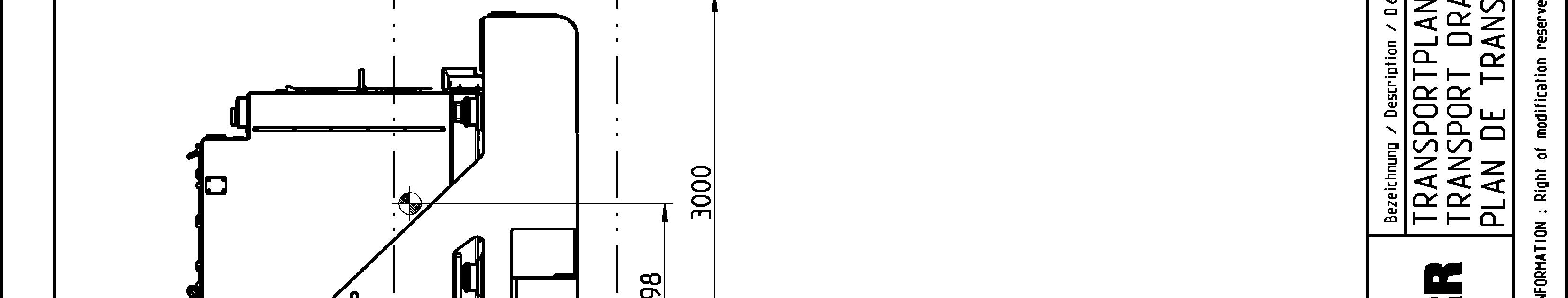
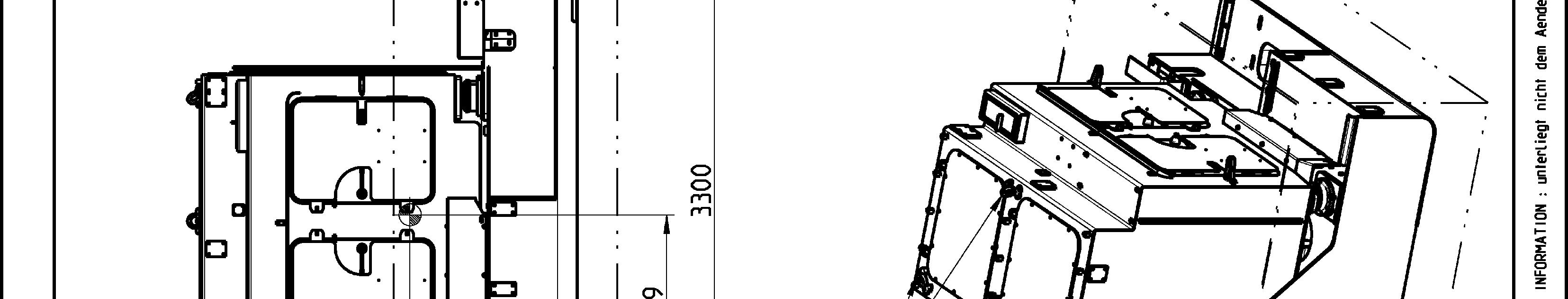
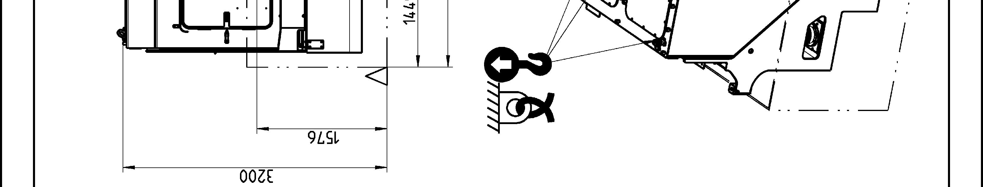
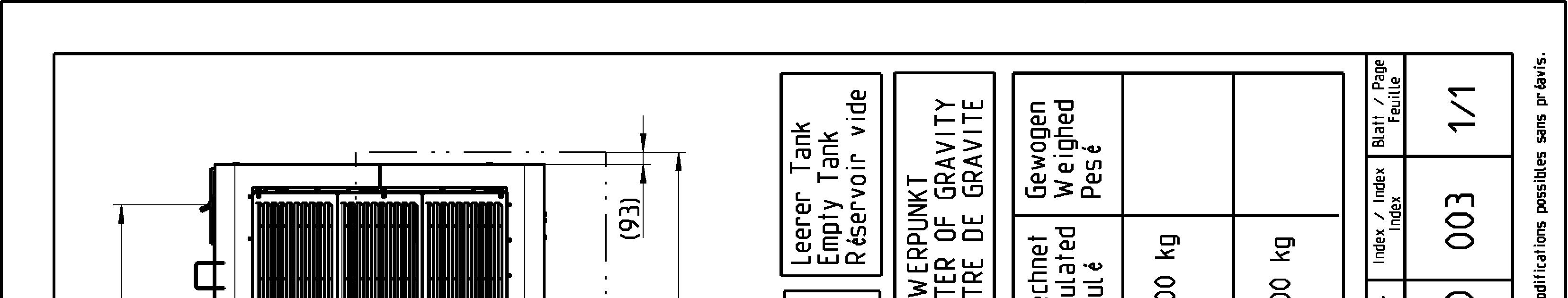
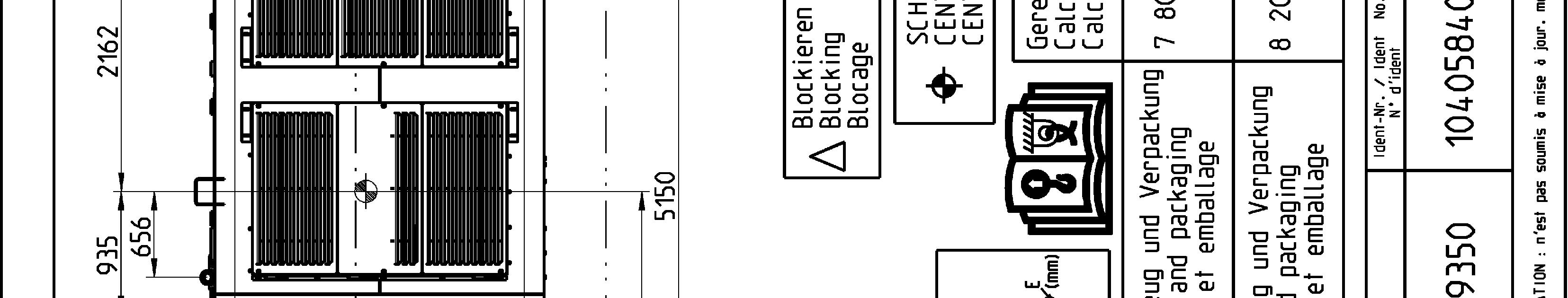
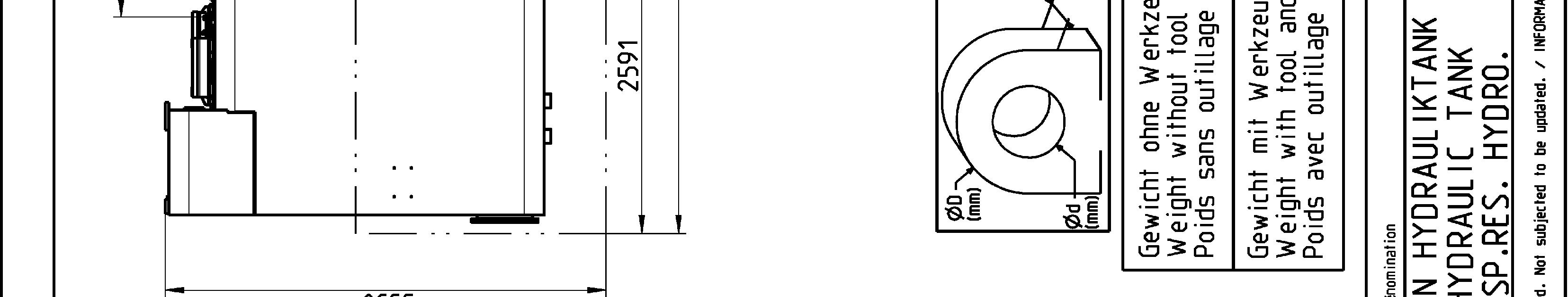
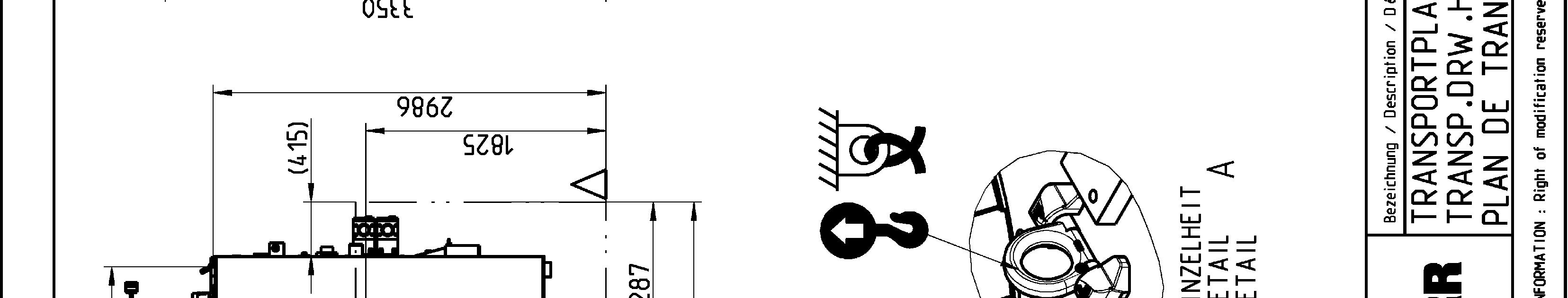
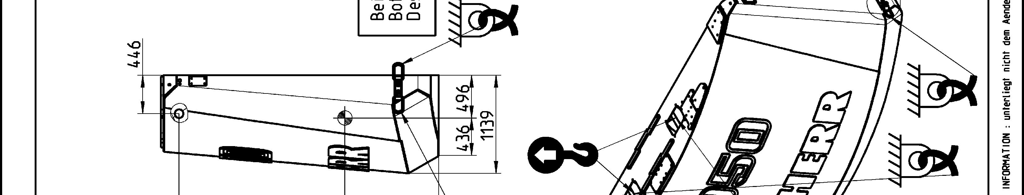
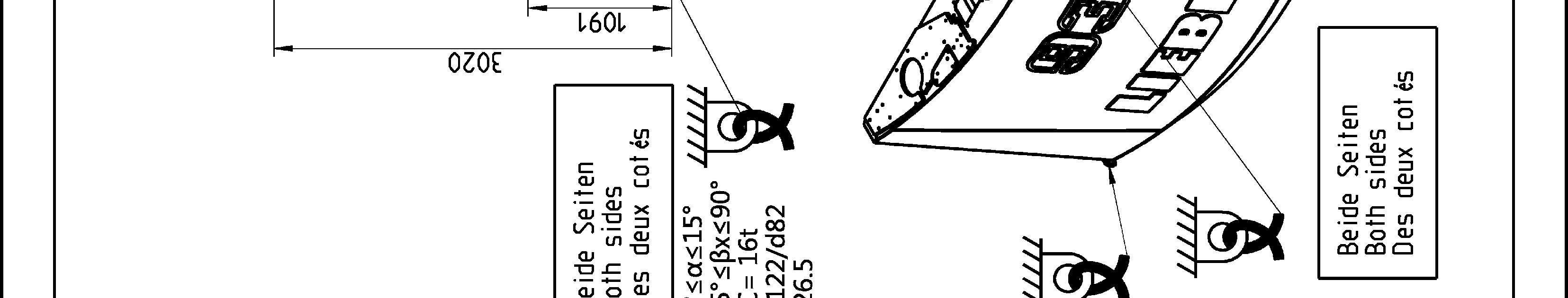
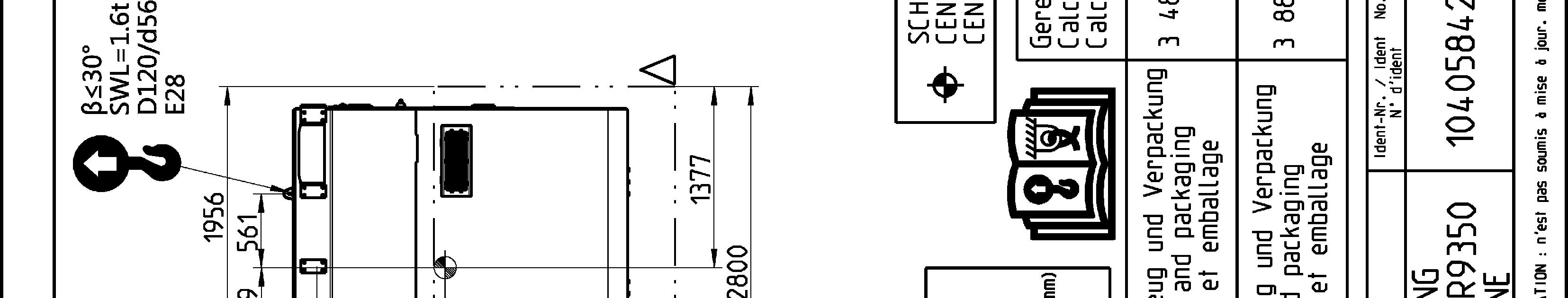
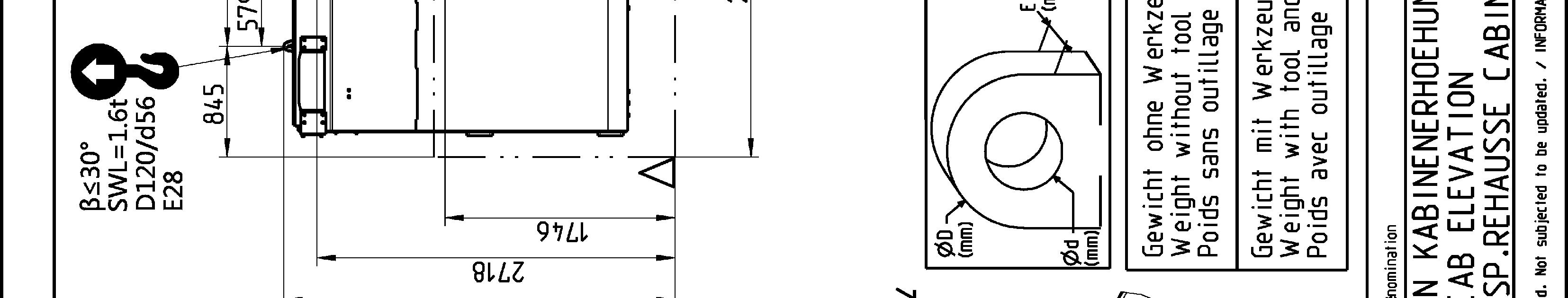
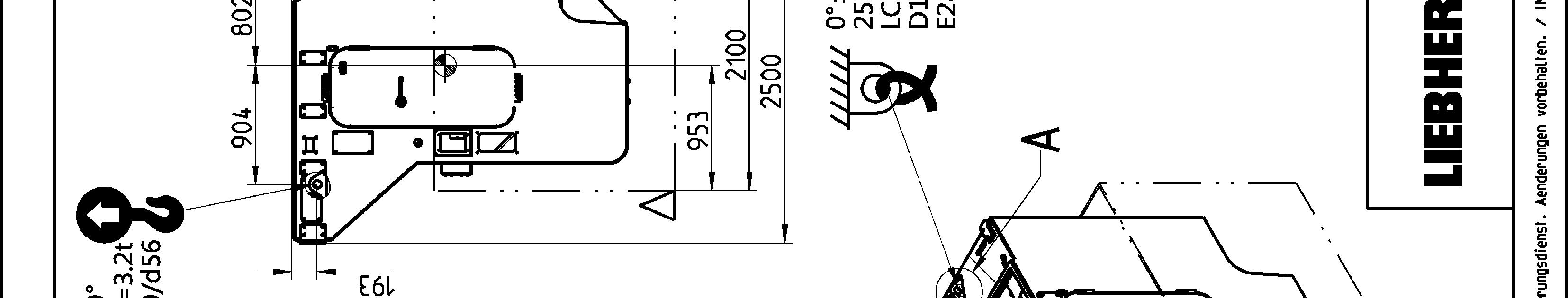
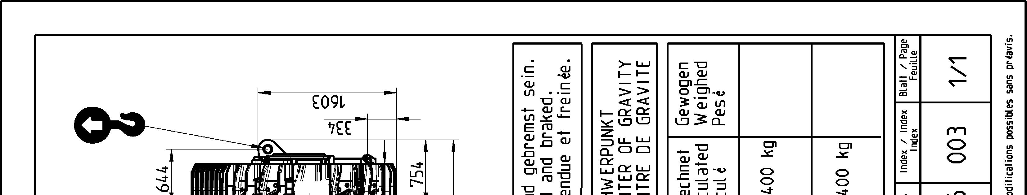
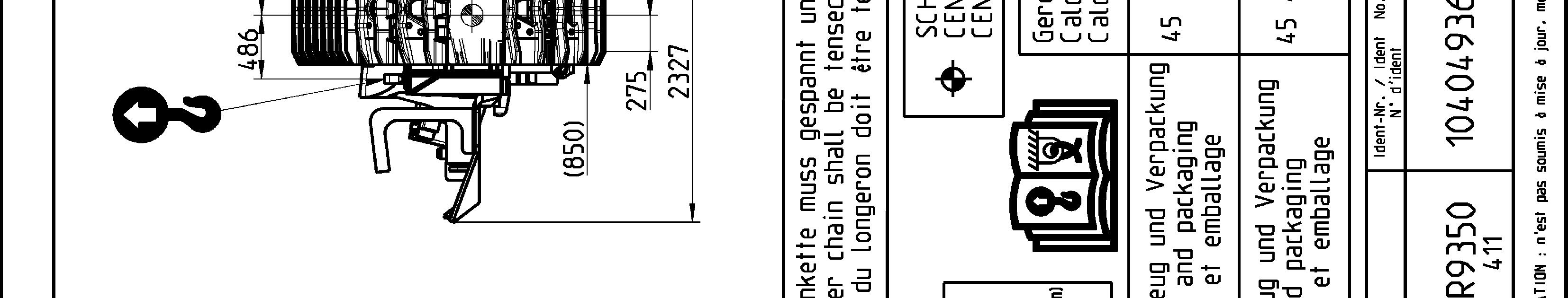
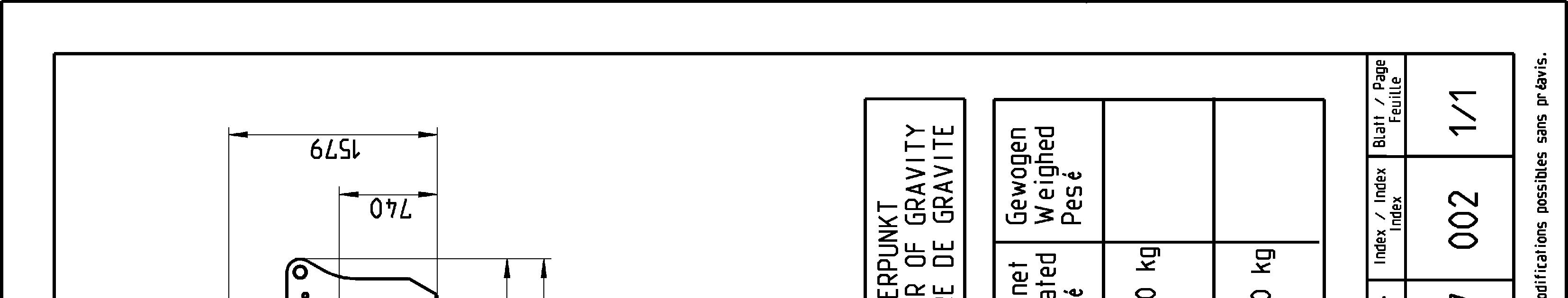
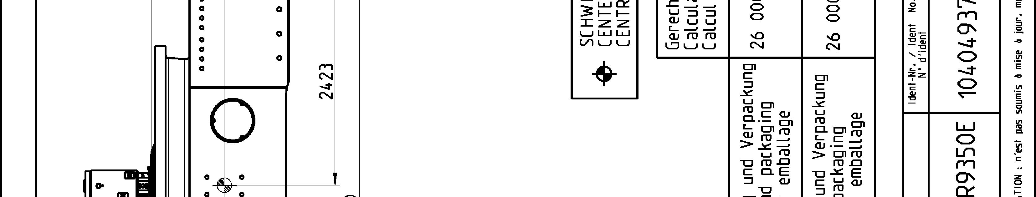
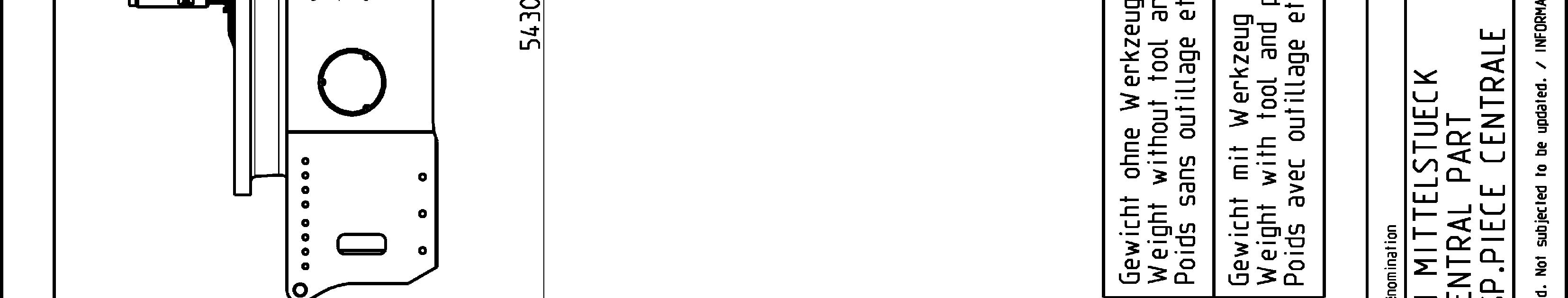
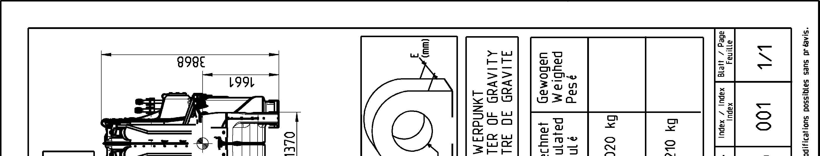
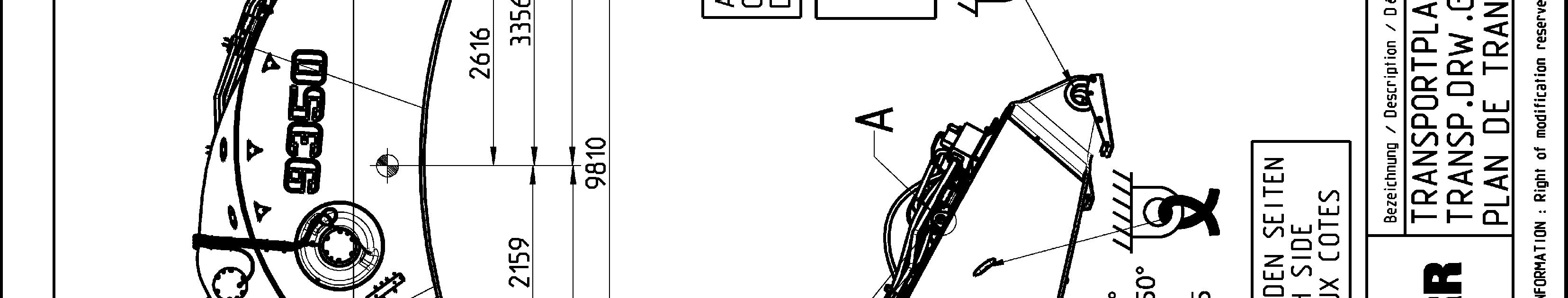
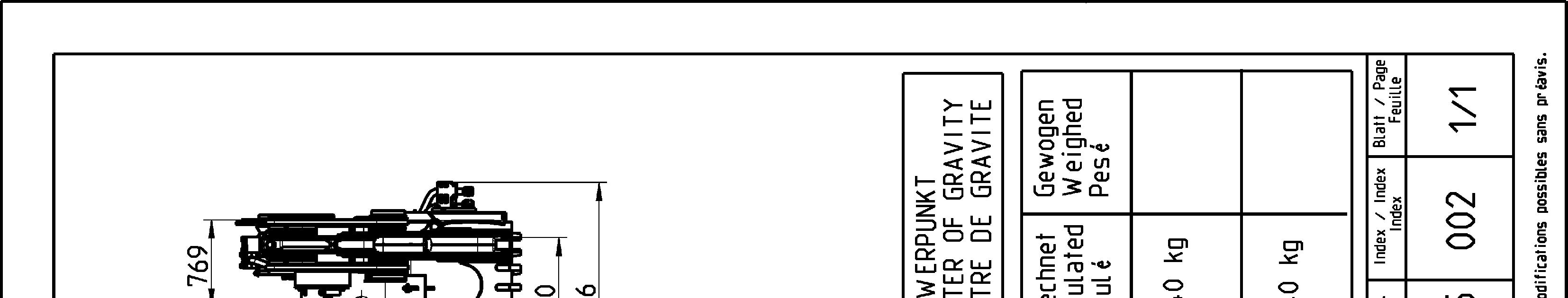
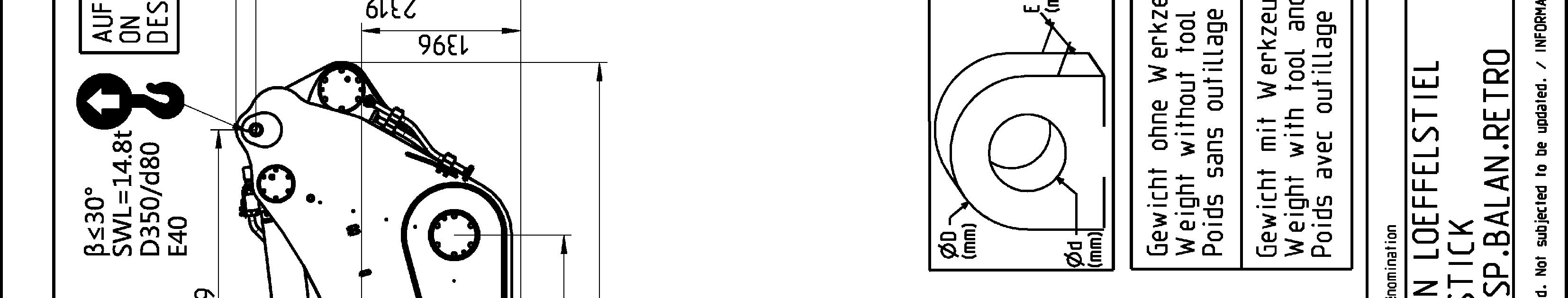
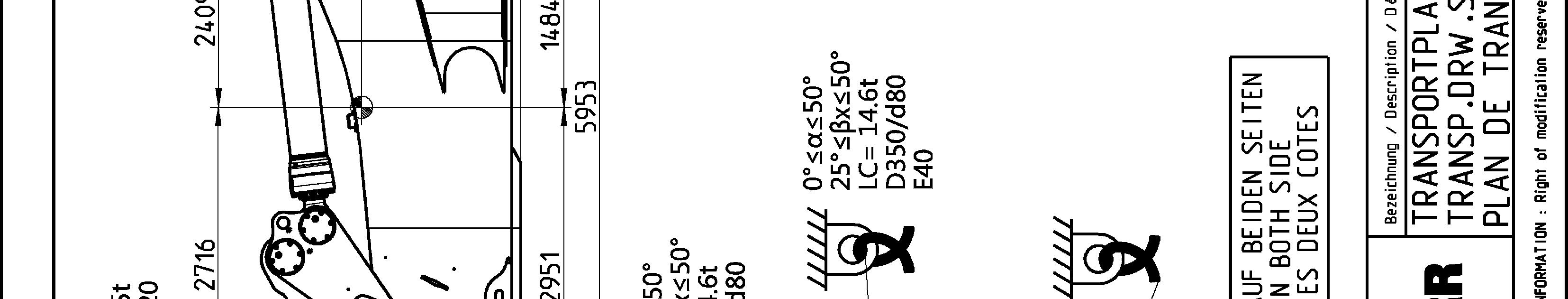
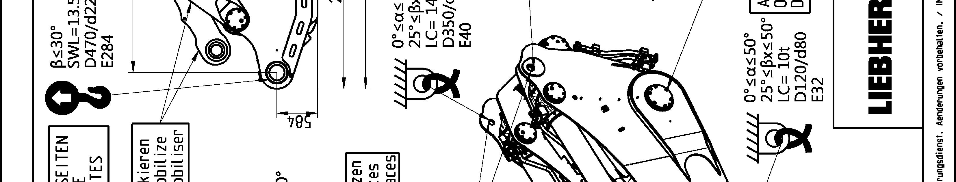
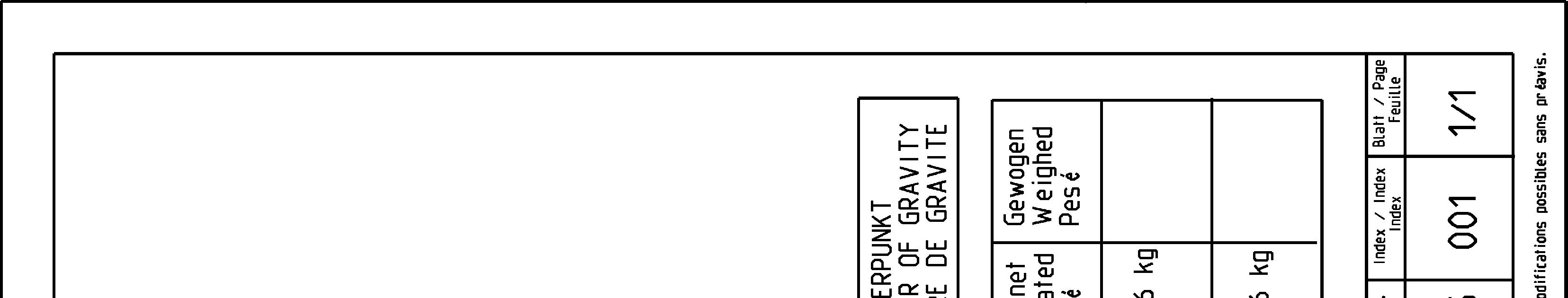
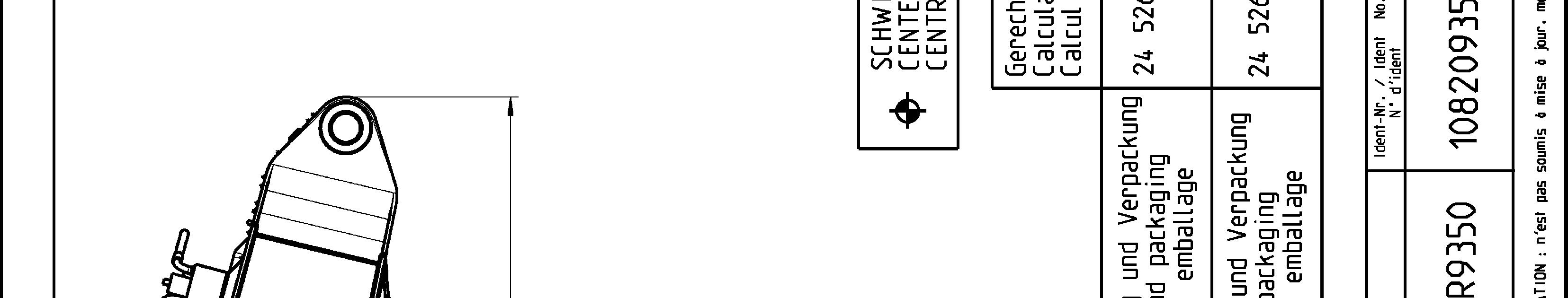
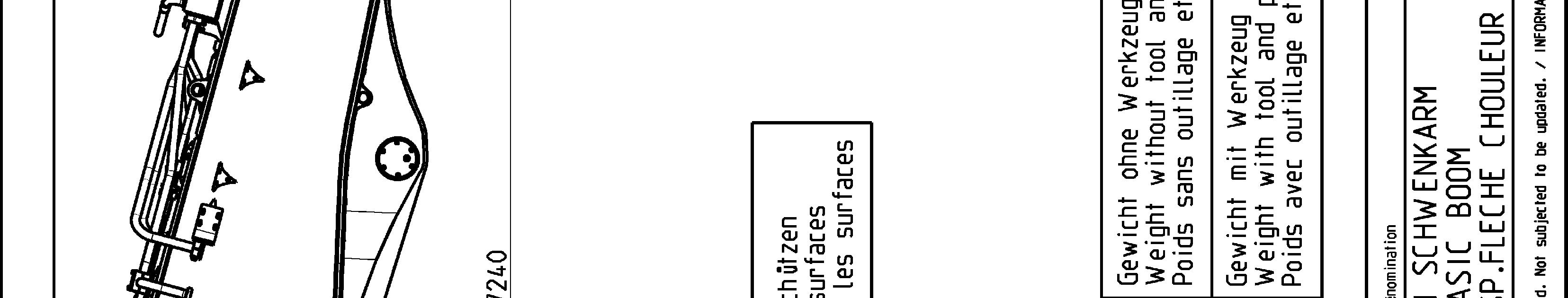
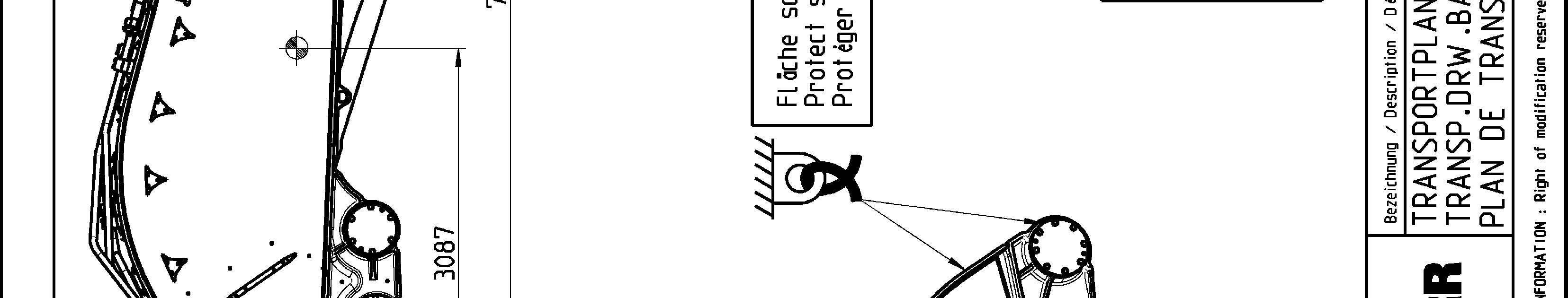
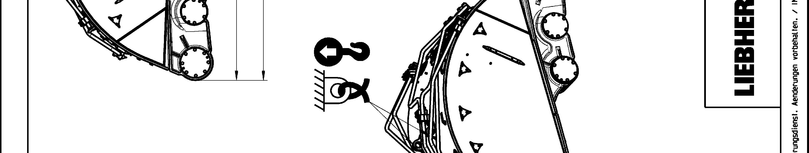
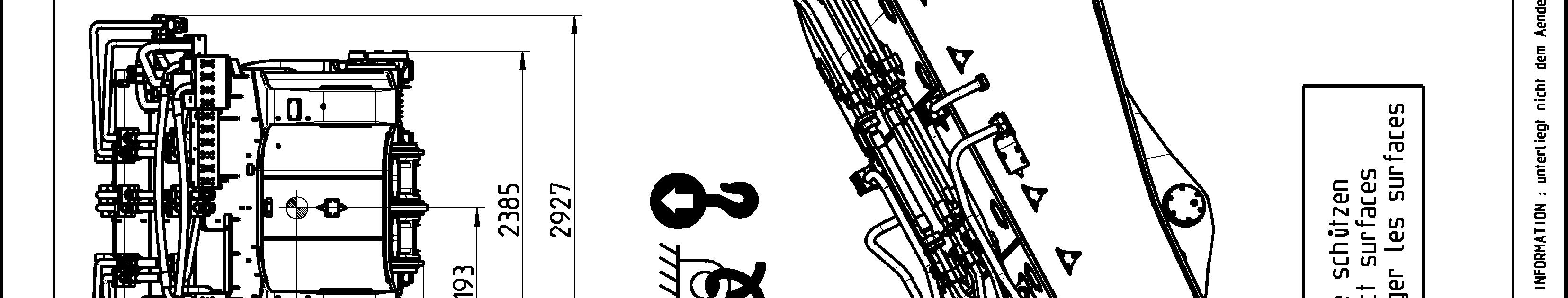
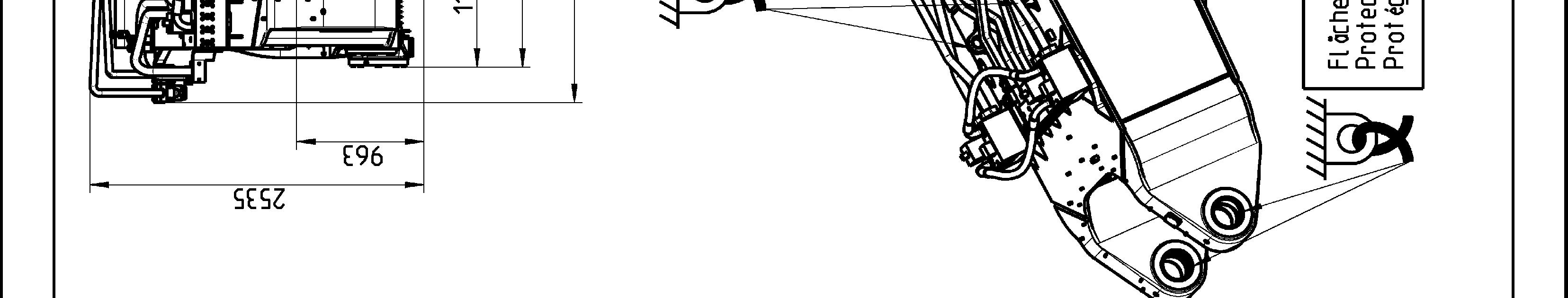
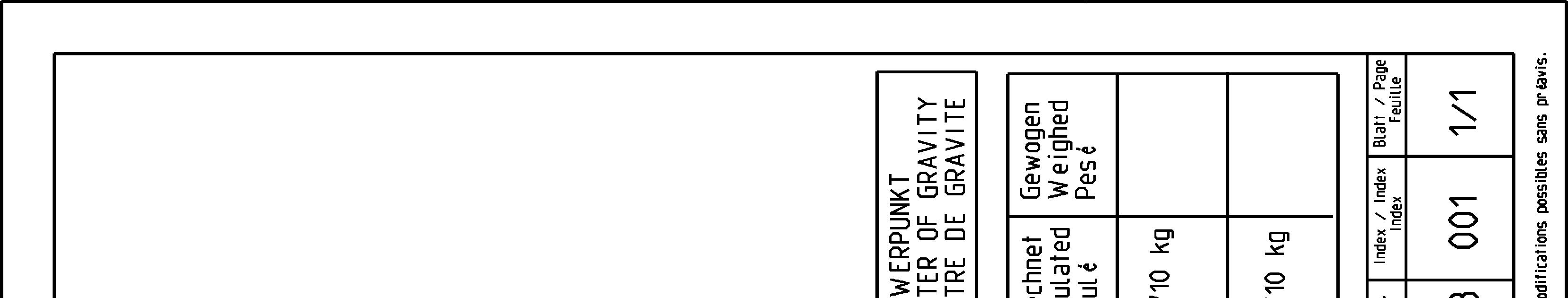
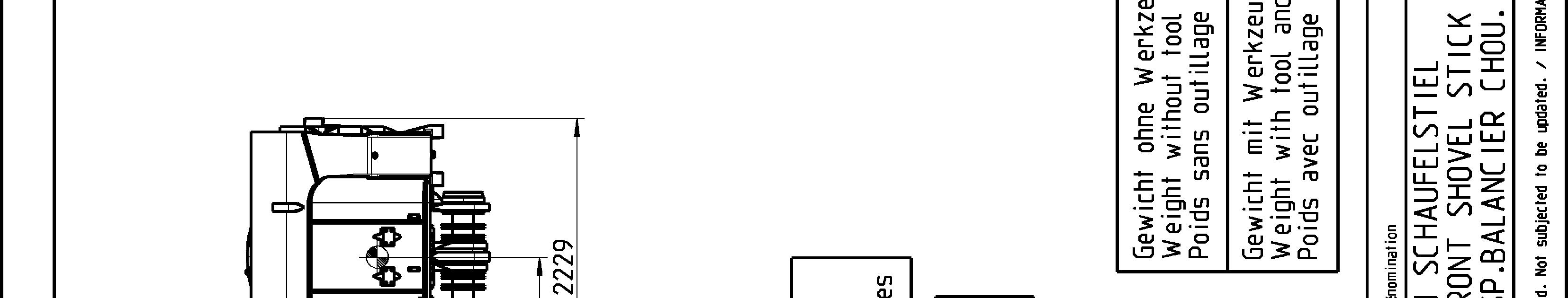
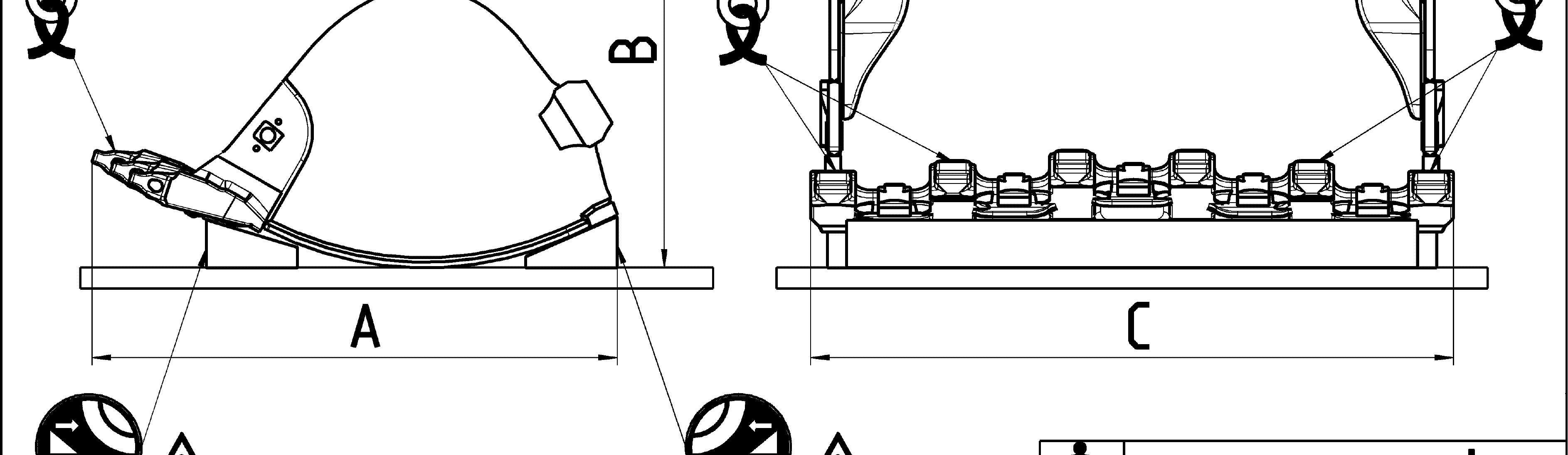
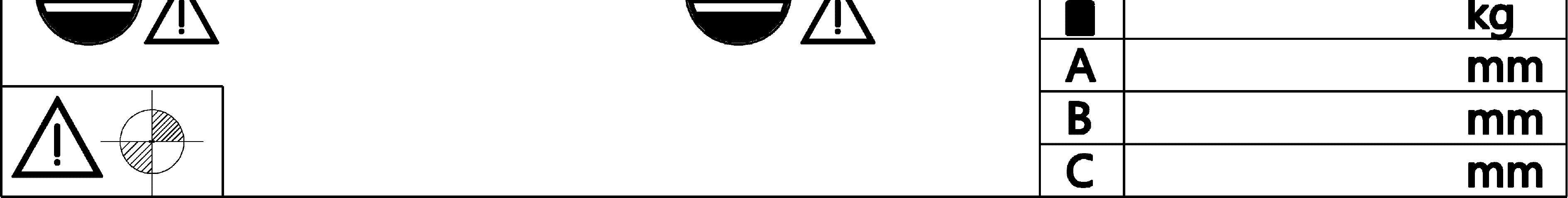
Transport drawings
The following drawings indicate the different lashing and lifting points on the elements of the excavator. Weight (with and without transport tooling and packaging), overall dimensions as well as center of gravity are also given.
Theaimofthesedrawingsistoensuresafeoperationduringtransport,handlingand storage.
Note!
Thelashing andliftingpoints areindicated onthe concernedelementsof the excavator by specific labels (see § "Signs on the machine"). To be easily recognized, lifting points are painted in yellow (in red if excavator is yellow) as well.
Danger!
Theliftingpointsgivenonatransportdrawingforanelementaredesignedtoliftthis element only and nothing else.
Never lift an assembly of several elements by the lifting points of only one of these elements.