18 minute read
Control and operation


The access and the outfit of the cab
Lateral emergency exit
You can use the rear left window of the cab as an emergency exit.
To open the emergency exit:
If the rear left window has an emergency handle: Pull the emergency handle on the inside of the window. The window seal breaks into two parts and the window is released. Push the window out.
If the rear left window does not have an emergency handle: Breakthewindowwiththeemergencyhammerwhichisinstalledbetweenthetwo left windows of the cab.
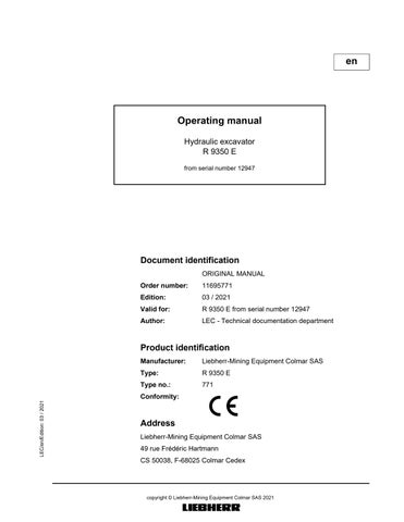
3.2.7Interior lightings
The interior lightings are switched on using the switch S41 on the Keypad. Press the switch S41 The lights E7 are switched on. Press the switch S41 again. Interior lighting E7 are switched off.
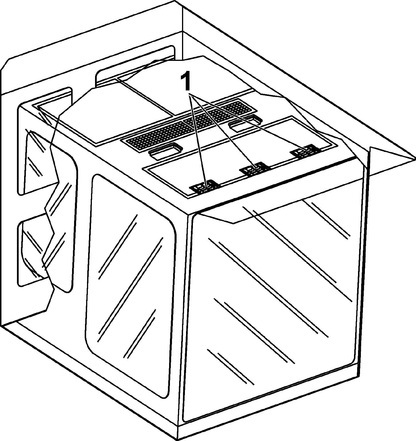
3.2.8Fire extinguisher
Theinterior of the cab is fittedwithfixingpoints allowing themounting of afireextinguisher. These fixing points are on the right side wall of the cab, on the frame between the two windows.
Note!
It is the responsibility of the owner of the machine to decide if it must be fittedwith afire extinguisher or not, considering the operating conditions and the regulations which apply in the country and at the point of use of the machine.
Caution!
If yourmachine is fitted with a fire extinguisher: Always comply with the operating guide on the body of the extinguisher, Make sure, all the inspections of the fire extinguisher which are prescribed by the regulations applicable to the operating place of the machine are accomplished.
3.2.9Windscreen wiper
Windscreen wiper
When the ignition is switched on, pressing switch S14 will activate the windscreen wiper.
Press switch. Intermittent switching LED I in the switch illuminates.
Press switch again. Continuous operation. LED C in the switch illuminates. LED I in the switch goes out.
Press switch again.
Windscreen wiper is switched off. LED C in the switch goes out.
Setting the interval time for the intermittent switching
The interval time can be set when the ignition is on by pressing switch S14.
Pressthe switch until the windscreen wiper is switchedoff (LED I in switchgoes out)
Press and hold switch. LED I in the switch flashes.
Release the switch when the desired interval time has been reached. The interval time can be set to between 2 and 10 seconds.
Windshield washer installation
When the ignition is switched on, pressing button S11 will activate the electric windscreen washer installation.
Press and hold button. Washingwaterwillbesprayedontothewindscreenthroughtheoutletnozzles. The windshield washer runs continuously.
Release the button.
Washing water will be stopped. Windshield washer will run continuously for approx. another 3 seconds.
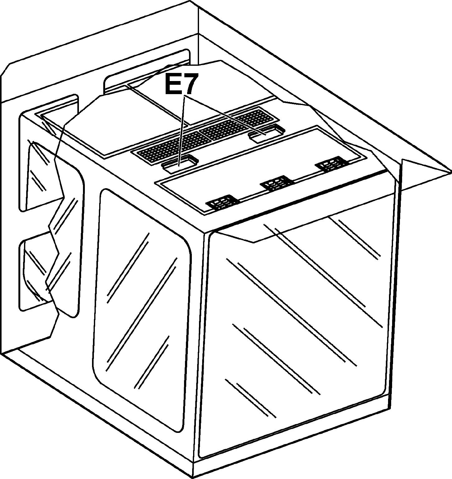
Windscreen washing fluid container
Fig. 3-42 Windscreen washing fluid container
The containerfor the windscreen washing fluid is located under the cabin in thecab elevation.
The container can be refilled via the service trap with ordinary windscreen washing fluid.
Volume: see lubricant chart
3.2.10Field
Monitoring cameras are installed on the excavator as follows in order to extend the posite side of the cab,
Danger!
Beforeusingtheexcavator,makesurethatthecamerasandtheoutsidemirrorsare correctly adjusted.
Regularly check mirrors and cameras for condition. If necessary: ce to get access to them.
Regularly check mirrors and cameras for correct adjustment. For maintenance intervals, refer to the control and maintenance chart. Replace damaged mirrors and cameras immediately.
To cover the correct area: Set the cameras and adjust the outside mirrors soas to be able to see a person standingoutofthehatchedareadefinedbythefourcheckpointsgivenonthefigure above.
3.2.11Lighting
Regularly check lighting devices for condition. If necessary: ce to get access to them. For maintenance intervals, refer to the control and maintenance chart.
1 Attachment floodlight
2 Attachment floodlight
2_2Attachment floodlight (optional, not represented)
2_3Attachment floodlight (optional, not represented)
6_3Counterweight floodlight (optional, not represented)
6_4Counterweight floodlight (optional, not represented)
6_5Counterweight floodlight (optional, not represented)
3 Top of cabin floodlight
4 Top of cabin floodlight
5 Counterweight floodlight
6 Counterweight floodlight
6_2Counterweight floodlight (optional, not represented)
7 Cab elevation floodlight
7_2Cab elevation floodlight (optional, not represented)
8 Hydraulic tank floodlight
8_2Hydraulic tank floodlight (optional, not represented)
Working light and attachment floodlights
Floodlights 1, 2, 3, 4, 7 and 8 as well as optional floodlights 2_2, 2_3, 7_2 and 8_2 can be activated using button S10 on the control keyboard.
Floodlights 3, 4, 7, 7_2, 8 and 8_2 constitute working light.
Floodlights 1, 2, 2_2 and 2_3 are attachment floodlights.
Press button.
Working light is activated.
LED 1 in the button illuminates.
Press button again.
Working light is deactivated.
LED 1 in thebutton goes out.
Attachment floodlights are activated. LED 2 in the button illuminates.
Press button again.
Working light and attachment floodlights are switched on. LEDs1 and 2 in the button illuminate.
Press button again.
Working light and attachment floodlights are switched off. LEDs1 and 2 in the button go out.
Counterweight floodlights
Floodlights 5 and 6 as well as optional floodlights 6_2, 6_3, 6_4 and 6_5 can be activated using button S22 on the control keyboard.
Press button.
Counterweight floodlights are switched on. LED in button illuminates.
Press button again.
Counterweight floodlights are switched off. LED in the button goes out.
3.2.12Heating/air-conditioning system
A heater and an air conditioner are installed in the cab as standard equipment. The heater is installed on the cab floor. The evaporator for the air conditioning system is integrated in the roof of the cab and the condenser is installed in the air conditioning unit behind the cab.
Cab ventilation
The heater as well as the air conditioner can both be used, at the same time and independently of each other to ventilate the cab.
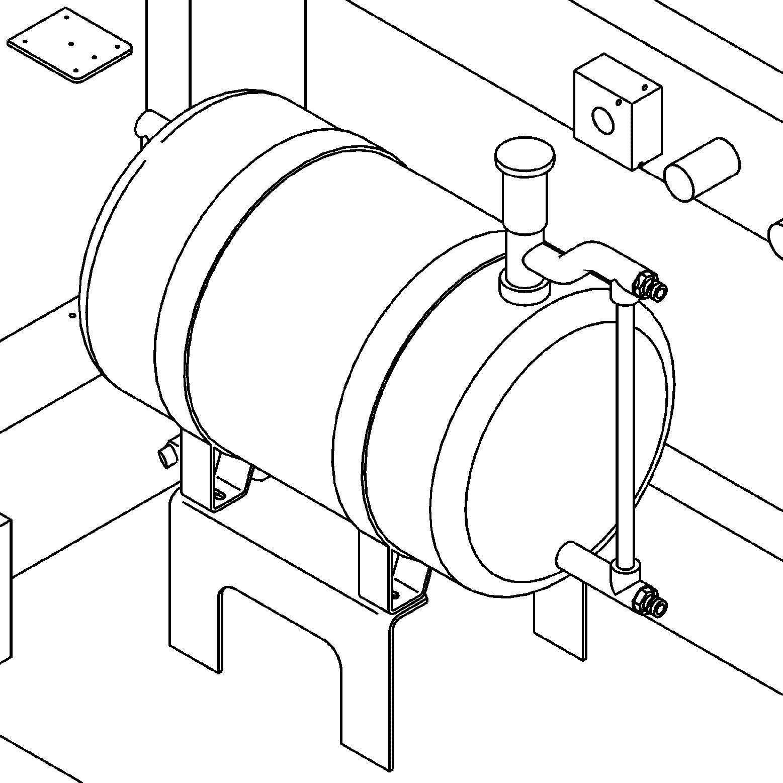
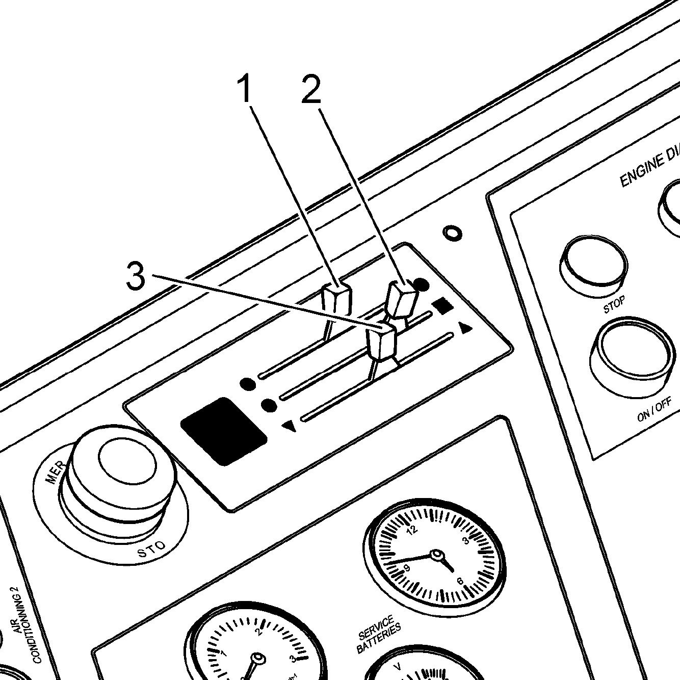
Ventilation with the heater
Push the lever 1 all the way forward. The water supply is closed. Push the button S12 to select desired air flow. The fresh airenters into the cab via openings on the steps and via the vents on the left and right front
Movethe lever 2 to regulate the amount offresh air/ recirculatedair cominginto the cab.
If the lever 2 is pushed forward, the fan recirculates theair in the cab.
Ventilation with the air conditioner
To ventilate the cab with the evaporator in the roof of the cab: Turn the air conditioner off with the button S2
Turn the blower fans on with the button S1
Selectthedesiredairflow withtherotaryswitchS1andtheventsoftheevaporator.
Heater operation
Move the lever 1
The amount of water running through the heat exchanger can be regulated. Iftheregulatorispushedallthewaytotherear,themaximumamountofcoolant flows to the heater.
Set the desired air flow with the button S12
Move the lever 2
The amount of fresh air recirculated and entering the cab is regulated.
Note!
The bestheating effect canbe reached whentheairis recirculated, which means, the lever 2 should be pushed all the way to the front. In this position, a small amount of outside air is mixed with the recirculating air in the cab.
To quickly defrost the windshield: Direct the warm air flow with the vents to the front. Push the sliding regulator 3 all the way to the rear. Sothemaximumairflowisblownviatheventsinthestepontothewindshield. Whenthe lever 3ispushedalltheway tothefront,partofthewarmairflowis blown against the left side window.
Air conditioner operation
The cab has an air-conditioning system as standard. The air-conditioning system is used to cool and ventilate the cab.
To adjust the air conditioner fan: Use the button S1
To turn on the air conditioner compressor and the condenser fan: Use the button S2 The air conditioner can only be turned on if the evaporator fan unit is turned on via button S1.
To select the desired air flow: Use the rotary switch S1
To set the desired air temperature: Use the rotary switch S2
To adjust the direction of the cold air flow: Use the vents on the evaporator unit.
To operate the air conditioner during the summer time: Push the lever 1 all the way to the front. Turn the heater blower off with the button S12.
To dehumidify the air in the operator’s cab: This procedure must be performed in case of very high humidity inside the cab during the colder season.
Theairconditionercanbeoperatedforashortwhilesimultaneouslywiththeheater in order to eleminate the excess of humidity and the condensation.
For best efficiency, select a highevaporator air flow viathe rotary switch S1 and operate the heater with recirculated air (lever 2 all the way to the front).
Dual air conditioning (optional equipment)
Whenyou switchthe excavator on, the automatic dualair conditioning systemis activated by default. The two air conditioning units are working alternately every 6 hours.
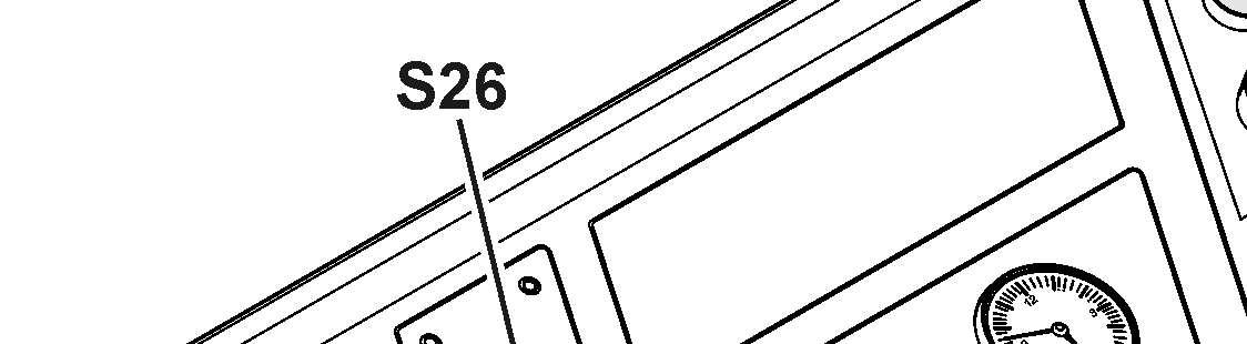
Control Board
Press"Dualairconditioning"buttonS26oncontrolboard(see§"Controlboard"). Automatic air conditioning mode is deactivated. First air conditioning unit is activated. Second air conditioning unit is deactivated. Press button again.
First air conditioning unit is deactivated. Second air conditioning unit is activated. Press button again. Automatic air conditioning mode is reactivated.
3.3Setting the machine into operation
Bringing the machine safely into service
it.
an authorized person, is in the work and movement area of the machine.
vers areclosed,but that locks areunlocked, tofacilitate the fight against fire in caseof.
against unintended movement. vicinity of the machine that it is about to start by sounding the horn.
Adjusting the operator’s standing position
controls in such a way that you are able to work comfortably and safely.
e must be set to the insulation position throughout operation.
Protection from vibration - seat adjusting and height of the operator. structions.
Utilisation in confined spaces el-operated heaters inadequately ventilated spaces. Before starting in closed areas, ensure adequate ventilation. Follow the regulations which apply for the particular area of use.
Starting the machine safely
l and tilt the safety lever up. alertpeopleinthevicinityofthemachine.
start the engine in accordance with the regulations given in the operating instructions.
tion.Ifnecessary,opendoorsandwindowstoensuresufficientfreshairsupplies. eratingtemperature.Lowoiltemperatures make the control unit react sluggishly. is operating correctly.
ea and then check the function of the travelandswinggearbrakes,thesteeringandthesignallingandlightingdevices. Lighting devices must always be clean.
Stopping the machine safely
it from rolling away.
ispossible,aligntheuppercarriagewith the undercarriage so that the sprockets locate at the back-end. This is the only one position which enables a secured access to every maintenance locationson the uppercarriage.
able. brakes.
erating instructions and tilt the safety lever up before leaving the cab. secure the machine against unpermitted use and vandalism.
3.3.1Starting / stopping the machine
General information
Note!
Whenusingthemachineataspecificheightabovesealevelandinconnectionwith certainoutsidetemperatures,theperformanceandservicelifeoftheelectricmotor is decisively affected. Undertheseconditions,thereisalsoanincreasedriskofoverheatingofthehydraulic oil.
Toavoid damagingtheelectricmotor,themotorpowermustbereducedwhenoperating in the following environmental conditions (sea level and exterior temperature): Refer to the Manual of safety, installation and maintenance of the electric motor manufacturer.
Before initial start up
Check the insulation resistance
Before initial start up and after alongperiodof non-use, andbefore theexcavator is connected to the power supply, check the insulation resistance:
The resistancemust never beless thantheminimum authorized resistance given in the instruction manual of the electric motor.
If insulation resistances should drop below the minimum values given, first verify whether the drop is from the insulators in the terminal boxes or the enclosure. If not, the motor or the high voltage enclosure, or the slip ring must be dried with aid ofthebuiltinheaterresistors,untilthedesiredvalueisreached(seeManualforsafety, installation and maintenance).
Check direction of rotation of electric motor
Before initial operation, or before restarting the motor after repairs to the electrical system,checkthedirectionofrotationof the electricmotor.Brieflystartandstopthe motor, and compare the direction of rotation to the arrows marked on the motor.
Activities before starting
Caution!
It is only possible to extinguish a source of fire when this one is accessible.
Before starting, unlock all locks on the panelling of the hydraulic excavator. In the event of fire, doors can be opened immediately and the fire extinguished.
For locks arrangements, see chapter "Maintenance".
Caution!
Theactivitiesreferredbelowinvolvescaldorburnhazardsduetohightemperature of the oil when the machine is at operating temperature.
Please read first the chapter "Maintenance" in order to get informations about carrying out these activities.
Before starting the machine, the following activities should be carried out on a daily basis: ing air intake.
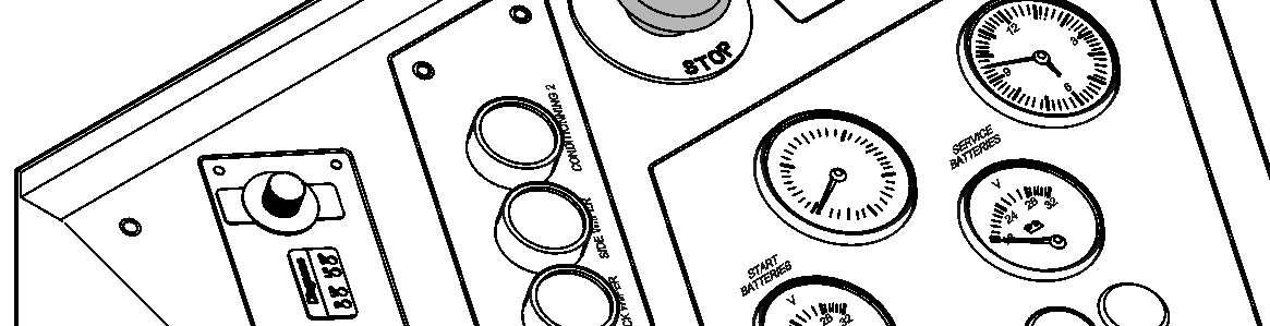
Switching on the electrical system
Ignition key switching positions
Switching on the 6kV control system
ThebatteryswitchS9_1mustbeinposition"on".Itisinstalledinanelectricalbox located on the top of the catwalk above access ladder. Turn the ignition key S1 to contact position 1
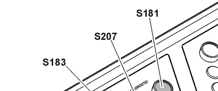
Push the button S183
The indicator light in the button comes on. Immediately after turning the system on, the display and the control unit will run through a selft test.
Make sure all indicators function properly after turning the electrical system on, i.e. the light emitting diodes (indicator lights and gauges) turn on for a short time thenthecompletefieldoftheLCDscreen200turnsmomentarilyblack(thematrix indicator is energised completely for a short time). Only the LED in button S22
Note!
If no automatic check of the keyboard and monitoring display is carried out when theignitionkeyisinthecontactposition,checkthatthemainbatteriesareswitched on.
Switching on the 400V control system
Make sure the 6kV control system is switched on. Push the button S207
The indicator light in the button comes on.
Service interval display
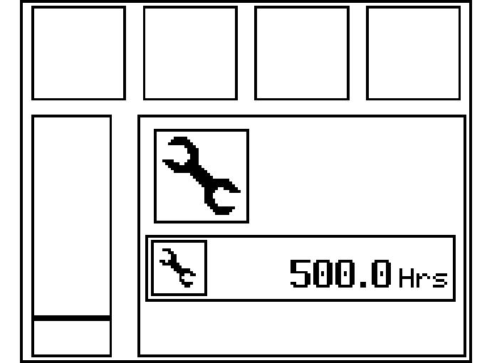
After the automatic check, any service interval that may be due will be indicated by a graphic symbol.
In place of the operating hours information, the number of hours relating to the service interval required will now be displayed. The service interval request will go out after approx. 8seconds.
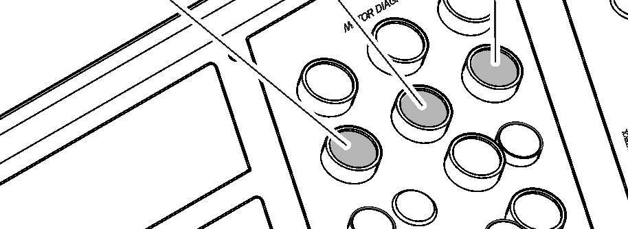
Starting the electric motor
Push the button S181.
The indicator light in the button comes on. After 8 seconds, the indicator light H110 on the control board comes on. It means that the servo oil circuit operates.
Caution!
Inordertopreventtheelectricmotorfrom overheating,motorstartingattemptsare limitedforagiven timeframe. Youmustobserveasufficienttimeinterval between two consecutive starting attempts.
Whenthemotoriscold,donotrestartmorethan5times.Thenwaitabout1hour before restarting.
When the motor is already warm, we recommend that you do not restart more than3times.Waitabout10minutesbetweentwoconsecutivestartingattempts.
Starting procedure when the exterior temperature is below -20°C (0.4°F)
For starting at temperatures below -20°C, it is recommended to equip the machine with a preheating system in accordance with LIEBHERR.
Warm-up procedure for hydraulic circuit
If the excavator is started when the exterior temperature is below 0°C, the operator must do the warm-up procedure:
Make sure that the hydraulic oil temperature is sufficient (refer to lubricating sectioninchapter5)todothisprocedure.Ifthistemperatureisnot sufficientwhena preheating system is installed on the excavator, keep preheating.
Startthemotorandletitrunwithoutloadduringthefirst3to5minutes,butatleast untilwarningsymbolsforlowhydraulictankpressurizationandforlowservopressure turn off on the LCD screen.
Caution!
Switch off the electric motor if the machine is not being used.
Step 1 - Open louvers and tarpaulins (if installed).
Step 2 - Carefully activate the working hydraulic circuits. Do not reach end positions of piston rod. Operate all movements at reduced speed: chment.Activatecylinderinorderandrepeat 10 times before moving to next cylinders: 4 times in each direction.
Step 3 - Repeat step 2 a second time.
Step 4 - Repeat step 2, with reaching end position of piston rod.
Step 5 - Repeat step 4 a second time.
Step6-Checkoiltemperatureinhydraulictank.Ifoiltemperatureisunder10°C, repeatstep4untiloiltemperaturereaches10°C.Ifoiltemperatureisabove10°C, move to step 7.
Step 7 - Start the travel hydraulic circuits very slowly forward and backward on approximately 10 meters. Repeat 4 times.
Aslongasthehydraulicoiltemperatureisbelowapresetvalue,thewarm-upsymbol is displayed on the SY field of the main screen. Duringthewarm-upprocedure,themainpumpsdisplacementislimitedto50%inorder to prevent damage to components.
The excavator can now be operated.
Notes after starting the motor
Caution!
Runthemotoruntilthehydraulicoilisatoperatingtemperature.Thecontrolsoperate sluggishly at low oil temperatures.
Move the machine carefully in an open space to test the function of the travel and swing brakes.
Check that the attachment is operating perfectly.
Switching off the electric motor
Push the button S182
The electric motor is stopped. The indicator light in the button S181 goes off.
Switching off the electrical system
Switching off the 400V control system
Push the button S208
The indicator light in the button S207 goes off.
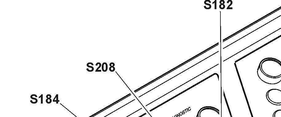
Switching off the 6kV control system
Push the button S184
The indicator light in the button S183 goes off.
3.3.2Starting aids (optional)
Functional description
Theexcavatorcanbefittedwithanoptionalpreheatingkit(requiredaccordingtothe ambient temperature of the work environment).
Preheating devices are installed on different components of the excavator (see § "Preheating components").
Thesedevicesaresuppliedbythefieldswitchorcanbesuppliedexternallybyagenerator set (Gen-Set).
The Gen-Set must provide at least 53kVA, 400V, 50Hz and must be connected with the connection box E1053, which isinstalled on the low voltage box S2
The preheaters are monitored and a warning light H104 on the control board will come up if a default is detected.
Preheating components
-40°C (-40°F)low temperature kit
Thiskitmust be activated every timethe excavator isstandingwithexternal temperature between -40°C and 0°C (-40°F and 32°F) and weekend or service and maintenance day.
The kit has following components: ters in hydraulic tank, gears, travel gears, hydraulic pumps and valve blocks),
Optional components
Following devices can be installed in addition to the previous kits: ers, lower covering, insulated PowerPack doors and fire protection sheets),
3.3.3Emergencyand safetyoperations Emergency shutdown
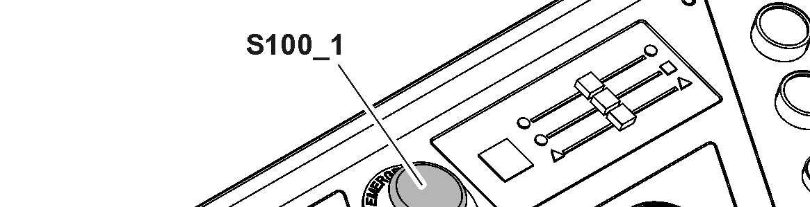
3-55 S100_1 on control board
To execute an emergency shutdown: Turnthestarterkeytothe"0"positionorpushoneoftheemergencystopbuttons S100_1, S100_2, S100_3, S100_4 or S100_5.

This action will stop the electric motor and switch off the 6kV control system. Using the emergency stop buttons willcause the hydraulic tank to be depressurized quickly.
If an emergency stop is operated, the ladderis lowered automatically.
Caution! Only use this shutdown method in case of emergency. Caution!
After ashutdownvia anemergency stopbutton,thebutton must beunlockedbefore attempting to restart.
Youmustwaitatleast10minutesafteranemergencyshutdownbeforeattempting to restart.
Safety controls for hydraulic pumps
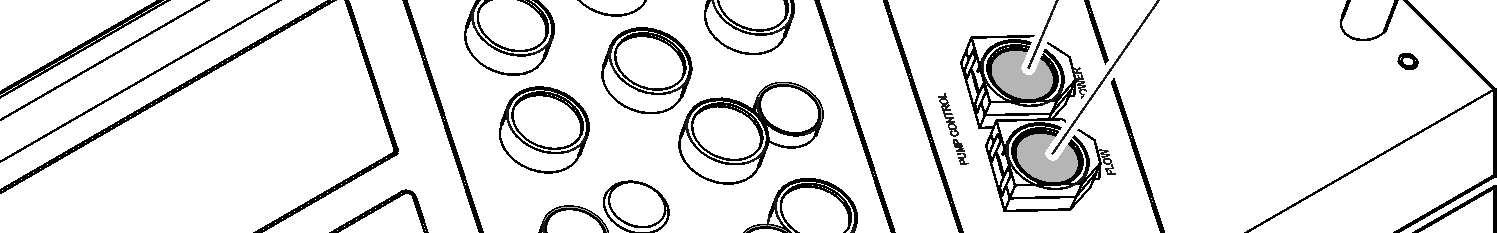
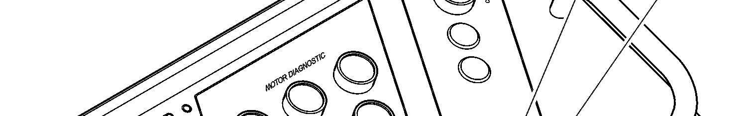
S73 Pumps power safety control
Pumps power safety control
S74 Pumps flow safety control
During normal operation of the excavator, the electronic horsepower control continuouslyadjuststhepumpflowtothepressurelevel oftheworkingcircuits.Ifatrouble occurs in the circuit of the regulator, the pumps are swivelled back to minimal flow. However it remains possible in this case to carry on the working with the machine (with somewhat reduced power) by pushing the button S73
Pumps flow safety control

Duringsafetyoperation,apresetvalue fortheflow ofthehydraulic pumpsisactivated by pushing the button S74.

Safetycontrols for electric system
H114 Safety batteries

Electric system voltage monitoring
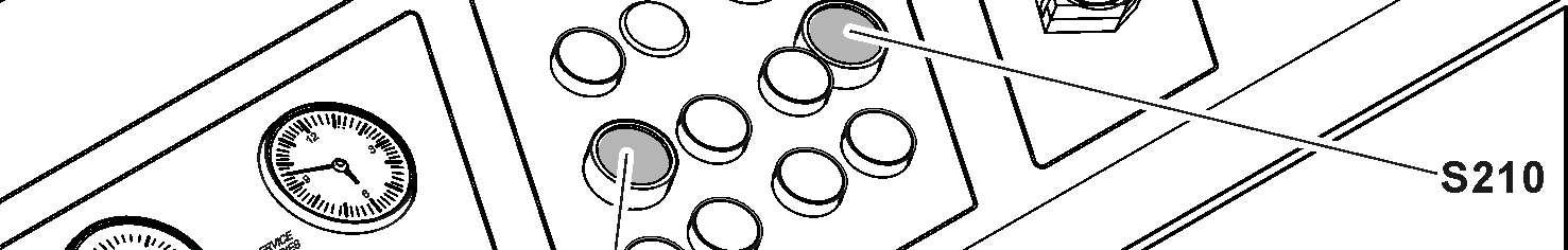
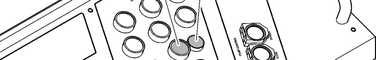
S118 Voltage monitoring relay
S185 Safety 24V
S210 Reset default end sensor S1/S2
The excavator has an overvoltage and undervoltage protection.
If an overvoltage or undervoltage is detected in the electric circuit: The electric motor is stopped. The indicator light in the button S118 comes on.
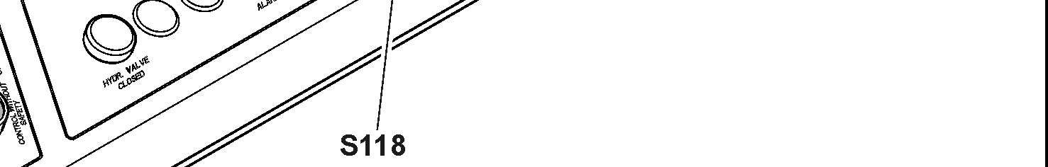

Push the button S118 to acknowledge the information.
Battery power supply
If the power supply from the electric plant stops, you can switch to the battery of the excavator to supply the service system and to lower the attachment if necessary.
Push the button S185.
Power supply is switch to the battery. The indicator light H114 comes on.
S1 and S2 doors protection
The excavator has protection on high voltage box S1 and low voltage box S2

If the door on S1 or S2 is open: The electric motor is stopped. The indicator light in the button S210 comes on. Push the button S210 to acknowledge the information.
Tow the machine
It is not permitted to tow the machine.
If you must move or recover a defective orunserviceable machine, contact Liebherr customer service.
3.3.4Driving
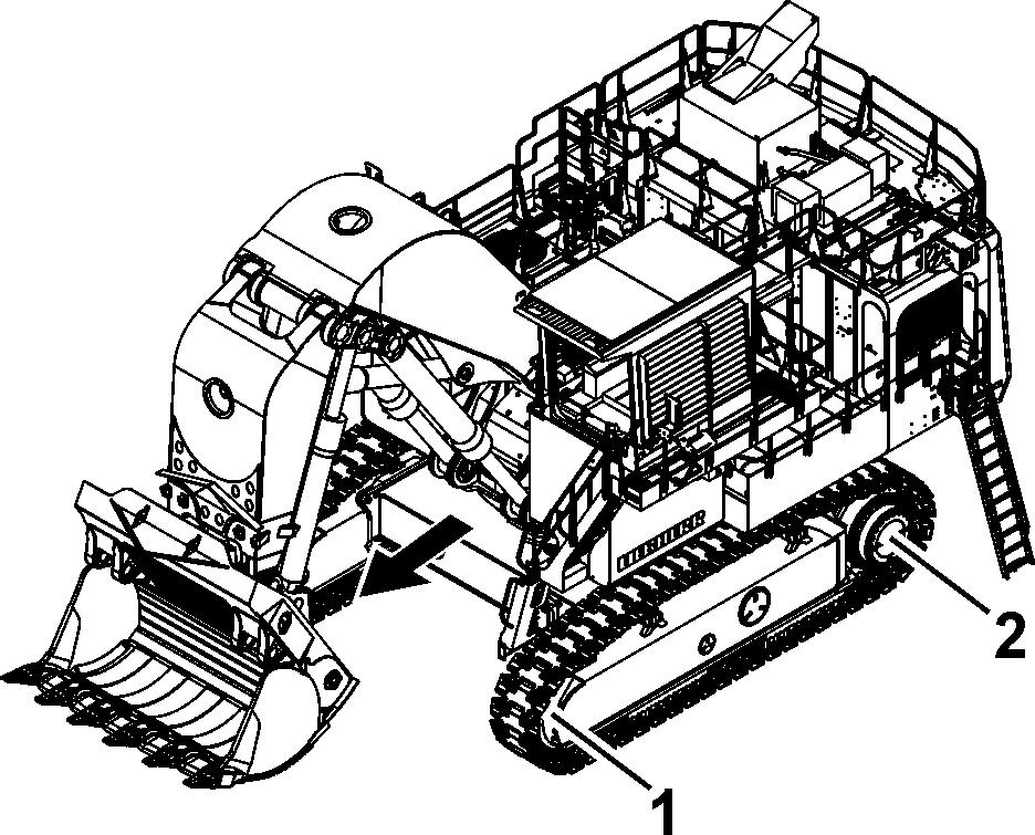
Driving straight ahead
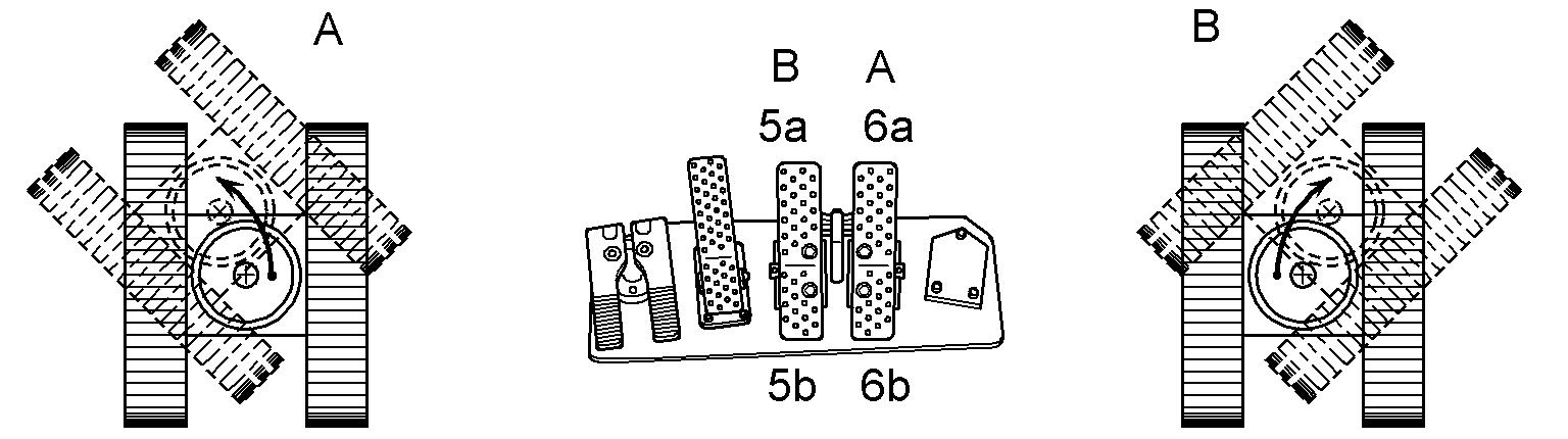
1 Idler 5a / 5b Pedal for left drive unit
2 Sprocket wheel 6a / 6b Pedal for right drive unit
Caution!
Whendriving,theuppercarriagemustberotatedtotheundercarriageinsuchaway that when driving forwards, the idler 1is infront and the sprocket wheel 2is at the rear.
Driving forwards:
Push both pedals forward (5a and 6a).

Reversing:
Caution!
Before reversing, ensure that the area behind you can be safely entered.
Push both pedals down (5b and 6b).
Turning on the spot
Turning left (A): Push the left pedal down (5b).
Push the right pedal forwards at the same time (6a).
Turning right(B): Push the right pedal down (6b).

Push the left pedal forwards at the same time (5a).
Turning with a crawler
Turning to the left (A): Push the right pedal forwards (6a).
Turning to the right (B): Push the left pedal forwards (5a).
Note!
If possible, avoid turning backwards in order to preserve the running gear parts.
Manual control of the travelling movements
Fig. 3-61 Hand levers for manual travel control
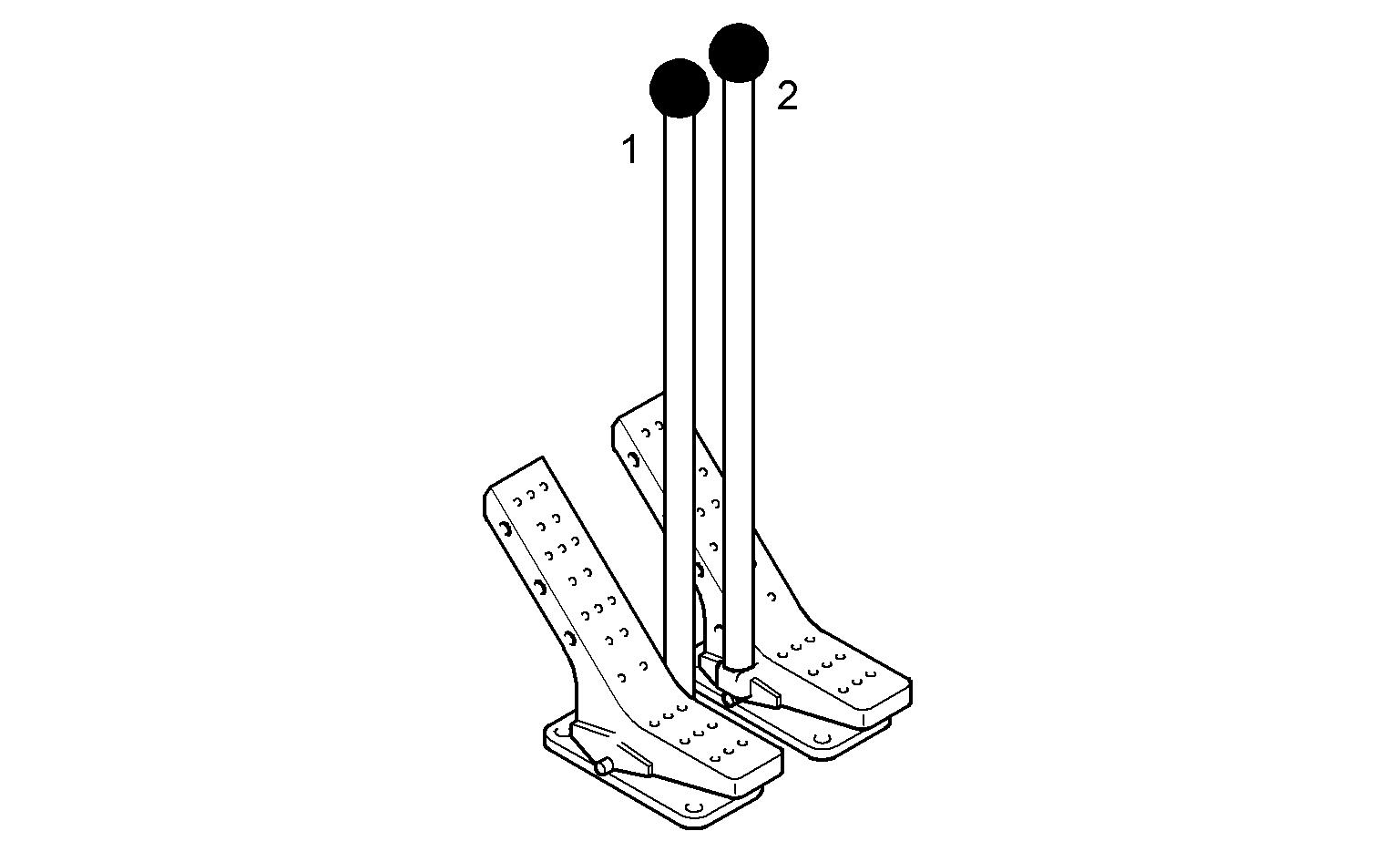
When particularly careful and progressive travel movements are required: Insert the hand levers (1 and 2) delivered in the tool box of the machine into the both pedals for travel movements. The travel movements can now be controlled manually.
Note!
When travelling the machine onto or off a low loaded, the travel movements must be controlled manually for safety reasons.
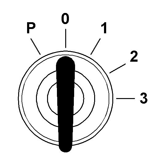
Controlling the speed
ThedrivingspeedisinfluencedbybuttonS21.Thetravelmotorscanbeoperatedin twodifferent positions:
Normal drive (position 1):
Maximum tensile force of both drive units at moderate speed.
Fast drive (position 2):
Reduced tensile force of both drive units at maximum speed.
Press switch S21
Transfer from normal drive to fast drive is activated. LED 1 in the button illuminates.
Whiledriving,themachinewillautomaticallyswitchfromnormaldrivetofastdriveas thegroundconditionspermit.Aftertransferringtofastdrive,LED 2illuminates.Ifthe ground conditions become more difficult again, the system will automatically switch from fast drive to normal drive. LED 1 illuminates.
Press button S21
Transfer from normal drive to fast drive is deactivated. LED 1 in thebutton goes out.
When button S21 is switched off, the travel motors remain continually in position 1.
Braking the machine
The hydrostatic travelling mechanism of the machine also functions as a service brake.
Disengage the pedals for the drive units. The pedals will return to the neutral position. The travelling mechanism will be stopped. The machine will be braked.
When the pedals for the drive units are in the neutral position, the hydrostatic drive prevents the machine from rolling off.
Intheneutralposition,theparkingbrakewillbeappliedautomaticallyafterafewseconds. The work equipment can, however, still be moved.
Actuating a travel pedal again will disable the travel brake.
Caution!
Disengaging the pedals quickly causes the machine to halt abruptly. Before starting the machine, always fasten the safety belt.
Cable reel (optional equipment)
The cable reel winds and unwinds automatically the supply cable.
H140 The cable reel is at the end
H141 The cable reel is near the end
H142 Cable reel failure
Ifthecablereelisneartheend,thewarninglightH141comesonandthebuzzerop- copyright © Liebherr-Mining Equipment Colmar SAS 2021 erates for 1 second.
Caution!
Risk of damage to the machine.
If the cablereel is at the end, the warning light H140 comes on and the buzzer operates for 1 second.
Do not travel more in direction of the end.
Caution!
Risk of damage to the machine.
If there is a cable reel failure, the warning light H142 comes on and the buzzer operates for 5 seconds.
Stop the machine immediately and tell the maintenance personnel.
Caution!
Risk of damage to the machine.
Make sure that theangle A between the undercarriage and the supply cable is never more than 45°.
3.4Working with the machine
Working safely with the machine
withthespecialfeaturesofthejobsite andanyspecialprecautionsandwarningsignals.Examplesofparticularworkenvironments would be on-site or traffic obstructions, the load-carrying capacity of the ground and any requirements to make the job site safe from public use.
ground.
of reduced visibility and changeable ground conditions.
e location of power and gas lines on the job site and takeparticularcarewhenworkingnearthem.Ifnecessary,informtheresponsible authorities.
laws, regulations and rules applicable at the place of use.
aerial lines. Do not allow the attachment to come near cables when working near electrical aerial lines. Risk of fatality! Inform yourself about required safety distances.
theeventofanytransferofelectricity: e danger zone to a sufficient distance, which had been touched or damaged, has been turned off! cured. squares, observe current traffic regulationsandifnecessary,ensurethatthemachinehasbeenmadesafeasperregulations beforehand. s of poor visibility or darkness. the safety belt securely fastened (if available). mediately. given in the operating instructions. while the machine is moving. ed while the engine is running. ble and that there is no danger of overturning. Only known loads may be moved with the attachment; this applies particularly when using the grab. ngitudinal direction when moving and hold the load as close to the ground as possible. nts which may tip the machine. Should the machine start to tip or slide sideways, however, turn the upper structure to face downhill and lower the attachment at the same time. uphill and not side on to the slope. lippery or inclined ground. opeandnotperpendicularto theslope,with the uppercarriage aligned with the undercarriage. or you could lose control of the machine. dieselenginemustrunatmaximalspeedandthespeedmayonlybereducedusing the foot pedals. allsafetyrequirementsarefulfilled,notablyinorder to protect the truck operator. vices specifically designed for the purpose. for the assistance of a spotter. Only permit one person to give you signals. load and to give indications to the with him. chmentcombination,thereisariskofcollisionbetweenthe work tool and the machine (uppercarriage and undercarriage). The greatest degree of care must be taken to avoid damage. chmentcombination,thereisariskofcollisionbetweenthe work toolandthecab,thecab protectionorthe boomcylinders.Thegreatestdegreeof caremust betakento avoiddamagewhenthe hoe teethcomewithinthis area. chmentcombination,thereisariskofcollisionbetweenthe worktoolandtheattachmentparts.Thegreatestdegreeofcaremustbetakento avoid damage. chmentcombination,thereisariskofcollisionbetweenthe liftringoftheattachment andthecaborthecabprotection.Beforeoperating,ensure that there is no risk of collision, especially on excavator with cab elevation. If necessary remove the lift ring. the soil. s can have various functions. Always check their functions when starting up the machine. a ditch without striking the attachment on the ditch walls. any other obstacles. tracted are not permitted, even when working in a longitudinal direction. to damage to the steel structures and machine components. special teeth for heavy-duty or special applications are required. th sidecutters or that areduringoperations with rocky material. This would prolong the work cycles and may lead to damage to the bucket as well as further machine components. et position may only be employed if the working tool or the attachment does not touch the material. drill into the material is not permitted. slowly back to the ground. hydraulics. Thiswould damage the machine. dozing blade (e.g. carving at the ceiling when tunnelling). ground collapse under the machine. inthefollowingMining applicationsis not approved or condoned by Liebherr: Scaling), without exception. material is un-blasted and non-fragmented material which requires the boom down (rod side) pressure to exceed 50 bar.
•warnanypersonnelin thevicinitynot tocomeclose totheexcavatorand not to touch it, someone turns off the voltage.
EXCEPTION: excavators used for loadingand unloading, see the part "Safe use when loading and unloading (particularly when loading and unloading wood)" on page72.
Otherwise, you must stop the excavator, turn off the radio and keep inside the closed cab until the end of thestorm.
The use of these Mining methods will result in increased fatigue levels to steel structures and components of the respective Liebherr Mining Machine and thereforewillsignificantlyreducetheexpectedlifetimeofstructuresand/orcomponents.
Working safely with the machine used for demolition application
are subject to specific conditions and mustbefittedwithspecialsafetydevices(forfurtherinformation,contactLiebherr customer service).
ditional safety instructions that follow. Before the operation of the machine ions are in the specified limits. ly. le local regulations. tures (e.g. FOPS, front protective grid) are not installed. or special tool as an additional force. the attachment or special tool is not safely positioned on the ground. tachment or special tool when the uppercarriage turns. its specifiedlimits.For moreinformation,
Incorrect use of the machine used for demolition application carried out only by trained specialist personnel. or special tool you use.
Do not stop it suddenly. Always move the attachment or special tool slowly and with constant speed movements. effects on the machine stability, reduce the height and the speed of the movement. the back-end.
Incorrect use of the attachment or special tool used for demolition application task. front protective grid.
Safe use of a hydraulic hammer or a hydraulicripper
ation, the use of a hydraulic hammer or a hydraulicrippercanresultinvibrations,shocksorstresseswhicharehigherthan in normal use. It may reduce the expected lifetime of structures and/or components.
ripper must be selected with particular care.WhenusingahydraulichammerorahydraulicrippernotpermittedbyLiebherr, warranty for steel structures and machine components will be ceased. n the machine on firm and level ground. ripper designed exclusively for breaking