8 minute read
Control and operation


S1 Ignition switch
S2 Control keyboard
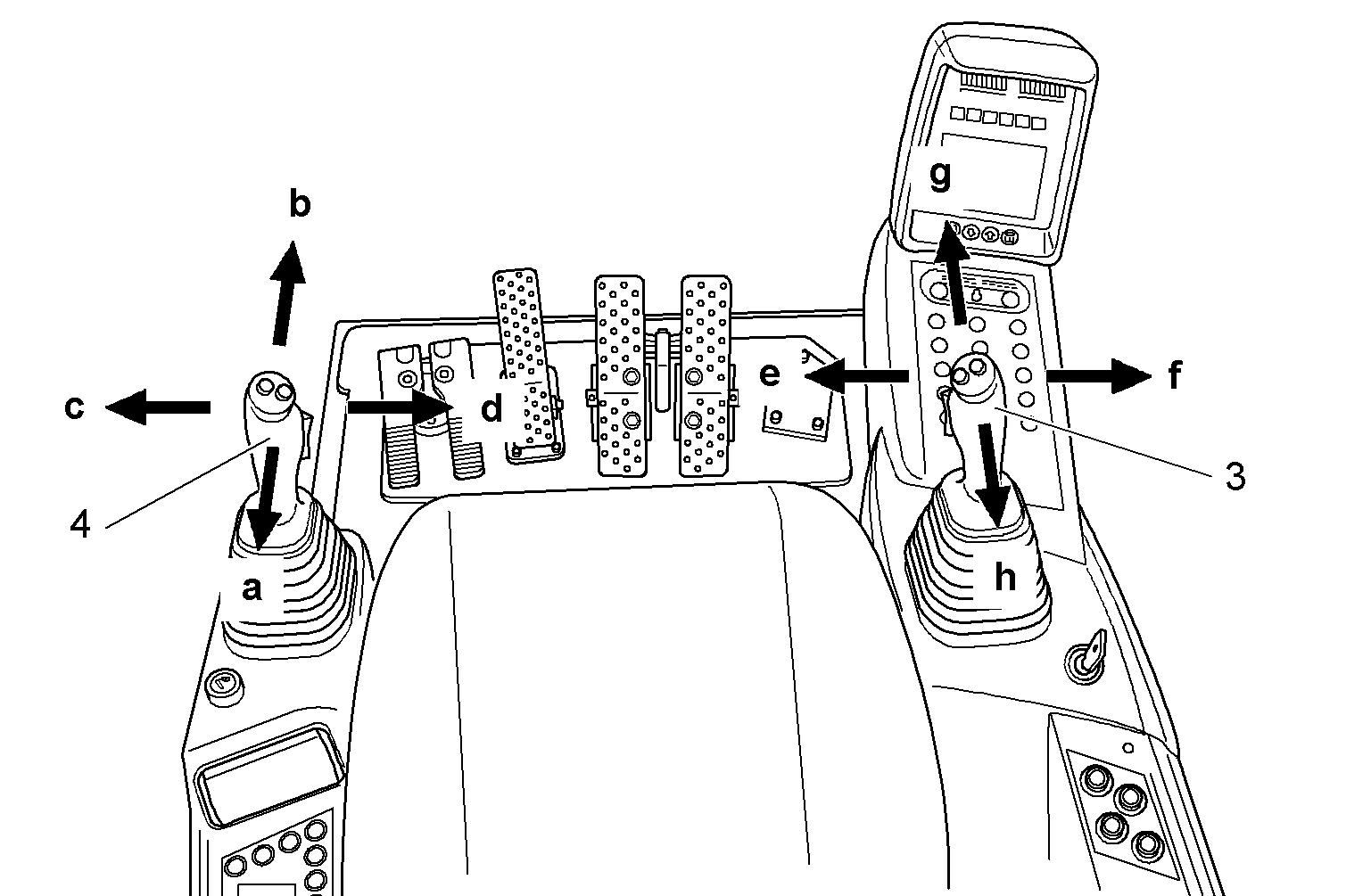
3.1.2Arrangement of joystick
U21 Left joystick
U22 Right joystick
Fig. 3-3 Joystick, right (3) and left (4) a and b: Stick is drawn in or out. c andd:Uppercarriageisrotatedto the leftortotheright. The right joystick (3) controls the boom or bucket and grab movements. e andf: Bucket willbe tilted up or down,grab will closeor open. g and h: Boom will be raised or lowered.
The left joystick (4) controls the stick and slewing movements.
3.1.3Keyboard
S10
Working light / attachment floodlights
Press button.
Working light on the uppercarriage is activated. LED 1 in the button illuminates.
Press button again.
Working light is disabled. LED 1 in thebutton goes out. Attachment floodlights are activated. LED 2 in the button illuminates.
Press button again.
Working light and attachment floodlights are activated. LEDs1 and 2 in the button illuminate.
Press button again.
Working light and attachment floodlights are desabled. LEDs1 and 2 in the button go out.
S11 Windshield washer
Press and hold button.
Washingwater will besprayedontothewindshieldthroughtheoutletnozzles. The windshield washer runs continuously. Release the button.
Washing water will be stopped.
Windshield washer will run continuously for approx. another 3 seconds.
S12 Cabin heater and/or additional cabin heater (optional starting aids)
Press button.
Heater fan(s) stage 1 is activated. LED L in the button illuminates.
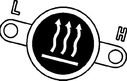
Press button again.
Heater fan(s) stage 2 is activated. LED H in the button illuminates. LED L in the button goes out.
Press button again.
Cabin heating is disabled. LED H in the button goes out.
S14 Windshield wiper
Press button.
Intermittent setting is activated. LED I in the button illuminates.
Press button again.
Continuous operation is activated. LED C in the button illuminates. LED I in the button goes out.
Press button again.
Windshield wiper is switched off. LED C in the button goes out.
In addition, the break time for the intermittent setting can be adjusted: Select the intermittent setting and keep the button depressed. After a few seconds, LED I in the button willstart blinking rapidly. Release the button when the blinking duration has reached the desired break time. Adjustment is possiblebetween 2 and 9 seconds.
S17 Swing brake
Press button.
Swing brake is engaged. Uppercarriage is locked. LED in the button illuminates. Press button again. Swing brake is released. LED in the button goes out.
S18 Overload warning device (optional)
Press button.
Overload warning device is activated. LED in the button illuminates.
Press button again.
Overload warning device is disabled. LED in the button goes out. No overload warning device is built in.
Press button.
The symbol for "No overload warning device is present" appears on the monitoring screen.
LED in the button illuminates.
Press button again.
The symbol for "No overload warning device is present" goes out. LED in the button goes out.
S19 No function
S20 No function
S21 High speed gear
Press button.
Transfer from normal drive to fast drive is activated. LED 1 in the button illuminates.
While driving, the machine will automatically transfer from normal drive tofast drive. LED 2 illuminates after transfer to fast drive.
Press button again.
Transfer from normal drive to fast drive is disabled. LED 1 in thebutton goes out.
S22 Counterweight floodlights
Press button.
Counterweight floodlights are activated. LED in the button illuminates.
Press button again.
Counterweight floodlights are disabled. LED in the button goes out.
S36 Special function 1 (optional)
Configuration and activation according to kit.
S41 Dome light
Press button. The interior lights are activated. Press button again. The interior lights are disabled.
S56 No function
S86 No function
P4 Motor start display
LEDs come on only at electric motor start.
S228 No function
S229 No function
S354 Travel brake
Press button.
Travel brake is engaged. Undercarriage is locked. LED in the button illuminates. Press button again. Travel brake is disabled. Undercarriage is unlocked. LED in the button goes out.
3.1.4Control
Indicator lights and gaugesControl switches copyright © Liebherr-Mining Equipment Colmar SAS 2021
Disable ladder or trap control lock function
For further information about correct use of this function, refer to § "Access ladder" in section "Entering or leaving the cab" of this manual.
Electric motor and electric systems functions
Forfurtherinformation,refertosection"Settingthemachineintooperation"ofthis manual.
Emergency stop and safety operation functions
For further information about correct use of these functions, refer to section "Emergency and safety operations" of this manual.
3.1.5Monitoring display
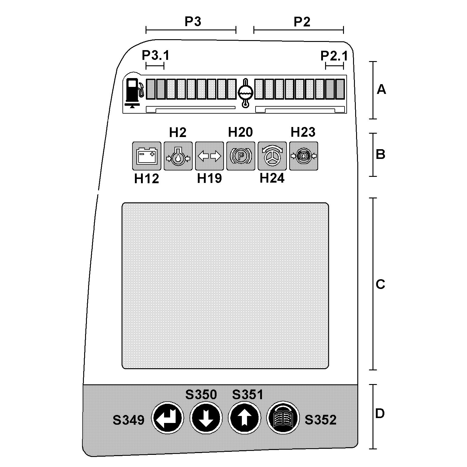
AreaD: Menu control for screen
Fig. 3-7 Screen menu control
The screen can be operated using the following 4 buttons:
S349: Back button
S350: Down button
S351: Up button

S352: Menu* button
* = Change from main to submenus move from page to page.
Area C: Screen
To change the screen contrast: Press button Menu and arrow button Up (higher contrast) or Down (lower contrast) simultaneously.
The value set will be saved.
To alter the brightness of the main screen: Press button Back and arrow button Up (brighter) or Down (darker) simultaneously.
The value set will be saved.
Note!
Alightsensorbuiltintothetopleftofthemonitoringscreencontrolstheillumination on the main screen, dependent on the brightness of the environment. Tracking is carriedoutusingthebuttonsandoriginatingfromthebasicsetting.Illuminationwill be automatically reduced in conditions of low environmental brightness.
To change the brightness and the contrast setting to the works setting: Turn off the ignition.
Press and hold the Up and Down buttons simultaneously. Turn on the ignition again.
Release the buttons once the automatic check is completed.
3.1.6Main screen
The main screen appears when the machine has been switched on and remains on displayuntilthescreenischangedovertothemenuselectionscreenusingtheMenu button.
EC Cable error display
INF Information
Main screen design
SY field
SY Symbols
TI Time
The upper field of the monitor shows, on the one hand warning and indicator symbols,ontheotherhandaclock,ifnomorethan4warningsymbolsareshown.Should more than two symbols be shown, so the clock is no more displayed and up to four symbols can be displayed simultaneously in the field SY.
Ifmorethan4 symbolsmust bedisplayed, thesymbols willbeshifttotheleft by one symbol every 10 seconds (see section "Warning symbols in the SY field" further in this chapter).
EC field
TheECwindowdisplaystheerrorcodesforelectricalfaultswhichoccur in theexcavator's electronics system (line errors, sensor errors etc.). A maximum of 7error codes are displayed simultaneously. If there are more than these 7 errors present, an arrow which points to where the other error codes are located will be displayed next to the error code window.
Press the Up or Down button. Theerrorcodewindowwillbeshiftedinthedirectionselectedintheerrorcode list.
INF field
The INF field displays information temporarily, in both text and graphic form. If more than 3symbols are to be displayed, the symbols will shift one symbol to the left approx. every 10seconds.
The information is displayed in graphic or text form and indicates specific operating states on the machine. (see section "Information symbols in the INF field" further in this chapter).
TI field
The machine operatinghours and the daily operating hours counter are displayed bottom right in this field.
The® symbol indicates that aquantitylimitationisactiveforthe pumps (see section
"Status of hydraulic pumps and electrical inputs and outputs menu" further in this chapter).
Menu navigation in the event of an error display
SY field, the user is returned to the main screen. The relevant error display is activated. Dependingon theerror(level ofurgency),thebuzzerwillsoundeithercontinuously or in short consecutive bursts. This symbol will be displayed in the INF field.
Danger!
Iftheerrordisplayedisnotrectifiedimmediately,thiscouldleadtopersonssustaining injury or the machine being damaged.
Rectify / have the error rectified immediately.
To switch off the buzzer, press the Back button. The error will be acknowledged and stored.
Warning symbols in the SY field
Each of the symbols which follow will be as Each error which occurs will be stored via the relevant error code.
E548
-E549 – Overheating winding
Thissymbolappearsifthereisaphasefailureofthedirectionofrotation(thewinding number appears in the top corner of the symbol).
E550 - E551 Overheating bearing
This symbol appears when the bearing is overheating (the bearing number appears in the top corner of the symbol).
E506 Oil in splitterbox is overheating
This symbol appears if the oil temperature in the splitterbox exceeds 85°C (185°F).
Stop the motor.
Find and correct the problem (splitterbox cooler dirty, ...).
E562 Low oil level in splitterbox
This symbol appears if the oil level drops below the minimum level.
Stop the motor.
Find and repair a possible leak. Add oil until the level is correct.
E564 High oil level in splitterbox
This symbol appears if the oil level in the splitterbox is above the maximum level.
Stop the motor.
Find and repair the problem.
It is possible that toomuch oil has been added, orthe oil level might have increased due to hydraulic oil entering via a defective pump shaft seal.
E591 Splitterbox oil pressure low
This symbol appears if the splitterbox oil pressure drops below 0.2 bar.
Stop operation and stop the motor.
Find and correct the problem.
Servo pressure low
This symbol appears if the servo pressure drops below 20 bar. Stop operation and stop the motor.
Find and correct the problem.
E504 Low hydraulic oil level
This symbol appears if the oil level in the hydraulic tank drops below the minimum level. At the same time, the pump are automatically returned to minimum flow.

Stop the motor.
Find and repair the cause of the oil loss.
Add hydraulic oil via the service flap or via one of the return filters.
Hydraulic oil warm-up procedure on
This symbolappears as long asthewarm-upprocedureis on,i.e.as long as thehydraulic oil temperature is below a preset value.
During the warm-up procedure, the main pumps displacement is limited to 50% in order to prevent damage to components.
E505 Hydraulic oil overheat
Thissymbolappearsifthehydraulicoiltemperatureinthetankexceedsapresetvalue.
Stop operation.
Continue to let the motor run and wait until the symbol disappears. If necessary.
Stop the electric motor.
Find and correct the problem (oil cooler dirty, blower or thermostat defective, ...).
E541 – High oil level in travel gear
This symbol appears if the oil level in the travel gear is above the maximum level.
Stop the electric motor.
Find and correct the problem.
Main pumps power reduction on Thissymbolappearsaslongasthehydraulicoiltemperatureisinapresethightemperature range.
Main pumps power is reduced progressively as long as the hydraulic oil temperature is in this range.
Main pumps output is set to zero if the hydraulic oil reaches the overheating temperature.
Allow the hydraulic oil to cool down to be able to operate the excavator then correctly.
E590 Low hydraulic tank pressure
This symbol appears if the hydraulic tank pressurization drops below 0,15 bar. Stop operation and stop the motor.
Find and correct the problem (check the air pressure system).
E566 - E567 - E568 - E569 Main pumps are contaminated
This symbol appears if metallic particles have been deposited on the contamination switchof one of the main pumps (the pump number appears in the top corner of the symbol).
Stop operation and stop the motor.
Notify the maintenance personnel.
E572 - E573 Swing pumps are contaminated
This symbol appears if metallic particles have been deposited on the contamination switchofoneoftheswingpumps(thepumpnumberappearsinthetopcornerofthe symbol).
Stop operation and stop the motor.
Notify the maintenance personnel.
E578 - E579 - E580 - E581 Main pumps overheat
This symbol appears if the temperatureononeof the mainpumps exceeds a preset value (the pump number appears in the top corner of the symbol).
Stop the motor.
Find and correct the problem.
E584 - E585 Swing pumps overheat
Thissymbolappearsifthetemperatureononeoftheswingpumpsexceedsapreset value (the pump number appears in the top corner of the symbol).
Stop the motor.
Find and correct the problem.
E 588 - Servo pressure high
This symbol appears if the servo pressure exceeds a preset value. Pumps are automatically set to minimal flow. Stop operation and stop the electric motor.
Find and correct the problem.
E 589 - Servo pressure low
This symbol appears if the servo pressure drops below a preset value. Pumps are automatically set to minimal flow.
Stop operation and stop the electric motor.
Find and correct the problem.
E544 External swing teeth greasing
This symbol appears if the swing teeth greasing system is defect.
Find and correct the problem. See also Lincoln servicing manual.
© Liebherr-Mining Equipment Colmar SAS 2021