Control and operation
Operating Manual
Attaching and dismounting equipment parts
Push the safety lever up.
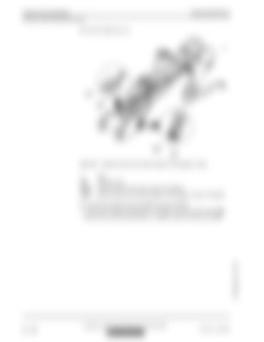
Fig. 3-97
Hydraulic lines for the rotary actuator of the grapple / shear
1
Stick
A/B VA1/2
Hydraulic lines Pressure ports for the quick coupler (if installed)
VA6/7
Manual valves for the rotary actuator of the grapple / shear (if installed)
Connect the hydraulic lines A and B to the tool as follows: A to the port of right turning direction. If installed, open the manual valve VA6. B to the port of left turning direction. If installed, open the manual valve VA7.
copyright © Liebherr-Mining Equipment Colmar SAS 2020
3 - 118
MJFCIFSS
R 9150 E / 12242219


