11 minute read
Control and operation


General working methods these operating instructions.
Transport the load close to the chassis, but with sufficient safety distance to the cab (swinging grab!) and as close to the ground as possible.
Advertisement
Caution!
Particularly when loading wood, it can be necessary when working with a grab to move with the working equipment raised and the load taken up. This will shift the centre of gravity of the machine upwards. The way the machine drives will be negatively affected because of this.
3.6.10Skimming
Skimming work can either be carried out using the bucket or with a skimming shield (optional extra).
The machine must be in the working position. The support should be raised.
Danger!
Serious risk of injury when moving the machine. Ensure that nobody is standing within the working area of the machine.
Caution!
The machine could be damaged. Never move the machine while the work equipment is touching the ground.
To skim with a backhoe bucket, lay this on the ground and move the stick slowly forwards and backwards. Move the boom steadily up and down while the stick is moving.
If a skimming shield is present (optional extra), lower it to the ground and move slowly forwards and backwards with the machine.
3.7Transport
Transporting the machine safely
able means of transport and lifting devices with sufficient load-carrying capacity.
tion.
an inclination of the angle value indicated in the "Technical data" section of this manual (machine must be able to walk up unaided) and should have a wooden cover to prevent sliding back.
any snow, ice and mud from the crawler / wheels of the machine.
pedals.
chine operator the required signal. t rolling back when the machine is driving up onto the flatbed.
hold the attachment securely over the loading area, drive very carefully up the ramp and onto the transportation vehicle.
restrictions during transport on hoe attachment, tilt the arm in and dismantle the bucket during transportation.
trailer, the upper structure must be secured facing the undercarriage using the stop bolts (only A devices). ing individual parts using chains and blocks to prevent slipping.
ignition key and tilt up the safety lever.
about the route to be travelled, particularly as they relate to width, height and weight restrictions.
under electrical lines and bridges and through tunnels.
me amount of care as was taken when it was loaded. Remove all chains and blocks. Start the engine as per the operating instructions. Drive ca the working attachment as securely as possible over the ground while doing this. Have a spotter guide you.
3.7.1Transporting the machine on a low loader
The excavator can be loaded and transported on a low loader completely built up or in self-driving configuration (machine operative without attachment and counterweight).
Caution!
The machine configuration for loading and transporting depends on the excavator type.
Refer to the transport drawings that follow for machine configuration (parts installed or not) and mass of components.
Caution!
The lashing operations depend on the excavator type.
Refer to "Excavator lifting and lashing operations" section and transport drawings that follow for lashing precautions, lashing points location, angles, etc.
Note!
For more information, refer to "Travelling procedures for mining machine" and "Excavator lifting and lashing operations" sections that follow in this manual.
Note
Respect the related local traffic regulations and safety instructions of profession corporations. If necessary, agree the machine, the transportation vehicle and the loading and fasten materials with the local legal permitted state.
Loading the machine onto a low loader
Different types of low loader can be used. In any case, the instructions that follow must be obeyed.
Danger!
The catwalk to access the cab door can be removed for the excavator transportation and there is, in this exceptional case, a risk of falling.
Do not climb up or down the machine without using external safety devices (for example a ladder or stepladder).
Note!
In any case, drive the machine forward onto the low loader with the idler 2 in front and the travel gear 1 in the opposite direction of the road traffic.
To climb a loading ramp:
Depending on the low loader type, the excavator must climb a loading ramp. In this case, the arrangements that follow must be made:
The ramp inclination must be flatter than the maximum machine travelling angle (refer to the technical data of this manual).
In any case, the ramp inclination angle must be < = 30°. Have the lashing material ready.
Install applicable anti-slip devices where necessary (coefficient of friction > 0.6). Clean any ice, snow or mud of the crawlers before starting to drive up the ramp. Align the machine accurately with the low loader or the loading ramp.
For careful and progressive driving, use the hand levers for manual travel control (refer to the related section of this manual).
Note
Have a spotter for providing the necessary signs.
When the machine is loaded, rotate the uppercarriage carefully 180° to set the excavator with the travel gear 1 in front of machine travel direction.
Danger!
If the uppercarriage is rotated 180° to the undercarriage, the driving and steering directions are reversed.
Drive and steer with increased caution.
To set the machine on the low loader:
The machine is loaded as described above on the transportation vehicle. Lower the attachment (if installed). Stop the electric motor.
Turn the ignition key to the contact position and release pressure lines by moving the joystick carefully some times.
Remove the ignition key and move the safety lever up. Close and lock all doors, covers and panels on the machine.
To secure the machine:
Danger!
Dangerous accidents can occur if the machine is allowed to slip on the low loader or on the loading ramp.
Secure the machine at the related points using applicable devices. Refer to lashing precautions and transport drawings that follow to identify the lashing points and the lashing angles.
Road transport
Danger!
Driving below obstacles which are not sufficiently high can cause dangerous accidents.
Prepare the itinerary before starting the route (height, width, weight, etc.). Drive under obstacles, particularly electrical lines, with increased caution.
3.7.2Loading the machine with a crane
The excavator can be loaded with a crane (e.g. onto ships or rail freight cars).
Danger!
The machine could slip or fall if incorrectly loaded. Only permit experienced personnel to secure loads and signal the crane driver. The spotter must position himself within the view of the operator or be in voice contact with him.
Ensure that the length of the lifting devices are correct.
Caution!
The machine configuration for the crane loading depends on the excavator type.
Refer to the transport drawings that follow for machine configuration (parts installed or not) and mass of components.
Caution!
The lifting operations depend on the excavator type.
Refer to "Excavator lifting and lashing operations" section and transport drawings that follow for lifting precautions, lifting points location, angles, etc.
Note!
For more information, refer to "Excavator lifting and lashing operations" that follow in this manual.
Lifting the machine:
Only use lifting devices which are sufficiently dimensioned or which have been specially developed by LIEBHERR for this purpose.
Set the machine in the configuration described on the transport drawings that follow.
Stop the electric motor.
Turn the ignition key to the contact position and release pressure lines by moving the joystick carefully some times. Remove the ignition key and move the safety lever up. Close and lock all doors, covers and panels on the machine.
Attach the lifting devices to the correct points indicated in the transport drawings that follow.
Danger!
Standing under the lifted machine is not permitted!
Lift the machine carefully with the crane and load. When restarting the machine, proceed only in accordance with the operating and maintenance manual.
3.7.3Travelling procedures for mining machine
The life expectancy of undercarriage components is based on standard working conditions with a maximum travel ratio of 5% per service meter unit. Working and / or travelling on uneven ground and / or abrasive material will influence the lifetime of the components and attract additional cost for the undercarriage components.
Downhill or uphill travel on a slope has also an effect on the life expectancy of undercarriage components and on their wear rate. Indeed, even if the slope angle is below the maximum permitted travelling angle, the increase of the slope angle causes the increase of the force and of the contact pressures applied on all track components (track pad assembly, sprocket, ...). On an indicative basis, the travel force applied on the track components is multiplied by two from a slope angle of 5° (8,7%) and is multiplied by 2,5 from a slope angle of 10° (17,6%).
In general travel action has to be kept to the lowest level that is possible. Minimize travelling with turning through a narrow turning circle and long distance travel.
To minimize the travel ratio, professional mine planning with longfront winning sections is preferred. If digging operations at various spots are necessary, a proper short term and long term plan of winning operations has to be employed to guarantee long term use of the excavator at one place before moving to another location.
However, if frequent machine movement is necessary, the following set of procedures defined by Liebherr to minimize possible machine damage, downtime and wear have to be taken into consideration.
General
In order to move the machine forwards: with the excavator in standard forward position, depress travel pedals all the way forward with the toes. Direction of travel is in the direction of idlers.
In order to move the machine backwards: with the excavator in standard forward position, depress travel pedals all the way down with the heels. Direction of travel is in direction of the drive sprockets.
Moving the machine during loading operations
Moving the machine during loading operations means adjustment of excavator digging and / or truck loading position of some meters.
Important procedures: position as close as possible to the excavator undercarriage. counter turning the undercarriage, is not allowed, because it could cause premature structural damage to the machine. the tracks where the machine will not turn, you must move the machine several meters forwards and / or backwards and attempt to turn again. in turning the tracks, i.e. if turning to the right, swing upper deck to the left and vice versa.
Walking the machine over distance
Walking the machine distances means any movement of the machine of more than 100 m or for a time period longer than 3 minutes, whatever comes first.
In addition to above mentioned guidelines, when moving the machine during loading operations, the following procedures apply: clean all very dirty parts of the undercarriage and remove the unwanted materials. with a heat gun, to monitor the temperature of the drive components, including the track and carrier rollers.
Danger!
During the movement of the machine, the person which is checking the temperature of the different rollers must always be out of the hazard area r of the machine and t and in radio contact with him.
For the checking of the temperature, the excavator should stop moving. And only when the excavator is stopped, the person could go in the hazard area r to check the temperature of the different rollers. The machine could only start moving again when the driver has seen the operator out of the hazard area r growing up about 20°C above ambient temperature, interrupt travel and only commence again after parts have sufficiently cooled. to speed up cooling procedure it is advisable to have a water truck standby, to hose the heating components during travelling or cooling break. vene with mine safety regulations, swing whilst travelling to equally load track rollers. However, always ensure that clear forward vision is maintained.
Travelling the machine down grades or upgrades
In addition to above mentioned guidelines, when moving the machine during loading operations or when walking the machine distances, the following procedures apply: indicated in the "Technical data" section of this manual (machine must be able to walk up unaided). When moving down the ramp never allow the machine to fall down on the attachment. When walking up the ramp never use attachment to assist the movement by pushing with the hydraulic power of the bucket, stick or boom.
7° (10%), it would be better to walk the machine down with the track motor first, i.e. the machine is moved backwards. es must be at the rear of the excavator.
Travelling the machine first time
The slide bearing (friction bearing) of the track rollers needs some time for runningin. If the bearing becomes hot at an early stage of machine life, this may cause lubrication problems during further life. Therefore when travelling the machine the first time aside from all above mentioned guidelines it is strongly recommended to move carefully and at reduced speed.
Note!
Warranty may become void if failure to recognize and comply with the recommended travel operating procedures, as outlined in this document, is noted.
3.7.4Excavator lifting and lashing operations
Danger!
For safety reasons, always consider th e precautions given in this section.
Lifting precautions
Lift element: sponding transport drawing, of other kind (cables, chains, slings) if necessary, es in accordance with the regulations, respecting the angles given on the sticker for lifting and lashing operations (refer to the description below).
Additional lifting precautions for backhoe buckets e center of gravity of the bucket. transport position as shown in the transport drawing.
When you lift the backhoe bucket, also obey the precautions that follow: the stickers placed on the bucket.
6 m, turn over the bucket safely.
Additional lifting precautions for shovel buckets
When you lift the shovel bucket, also obey the precautions that follow: the stickers placed on the bucket.
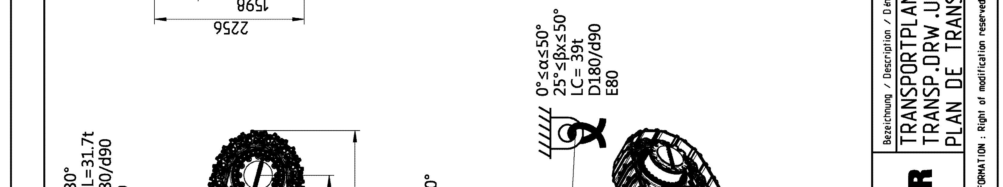
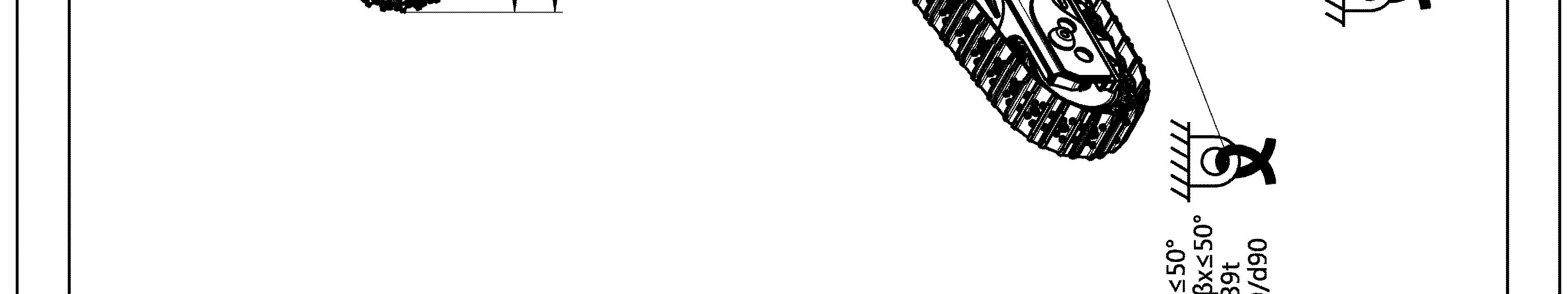
Lashing precautions
Lash element: e center of gravity of the bucket. in order to ensure safe lashing, sponding transport drawing, respecting the angles given on the sticker for lifting and lashing operations (refer to the description below), supporting surface so as to avoid element to slip (e.g. using wooden parts, nonslip mats...), iction is guaranteed by manufacturer certificates, between each contact surface (e.g. between the load and the support, between the support and the flatbed trailer), act surfaces between the flatbed trailer and the load carried are free of dirt, ice, snow, oil and grease.
Additional lashing precautions for backhoe buckets
When you lash the backhoe bucket, also obey the precautions that follow: he center of gravity of the bucket. tions. The height B1 gives the correct transport position as shown in the transport drawing.
Additional lashing precautions for shovel buckets
When you lash the shovel bucket, also obey the precautions that follow: he center of gravity of the bucket.
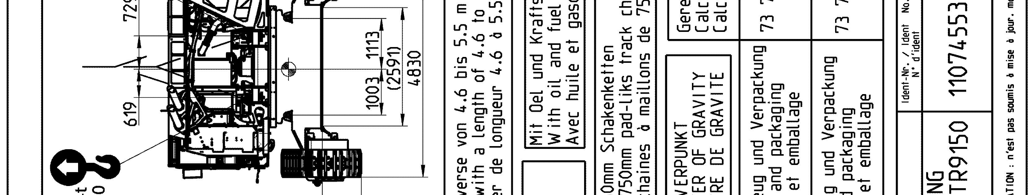
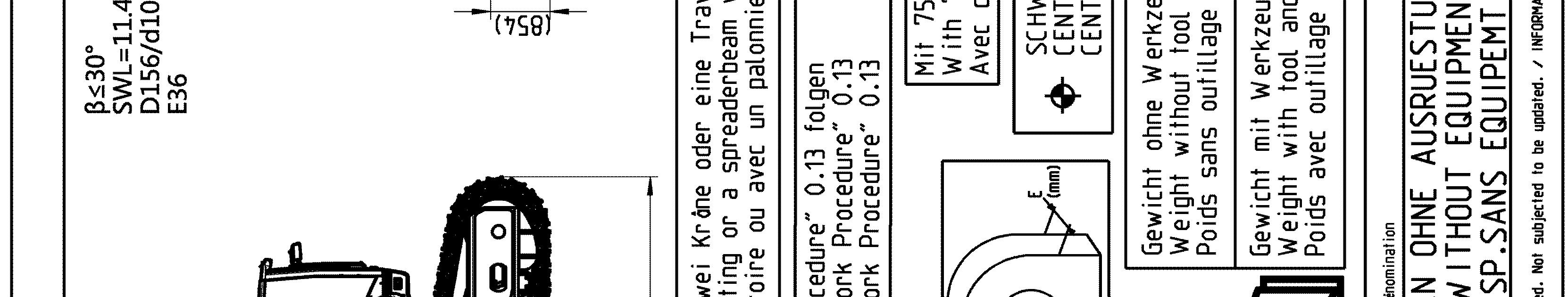
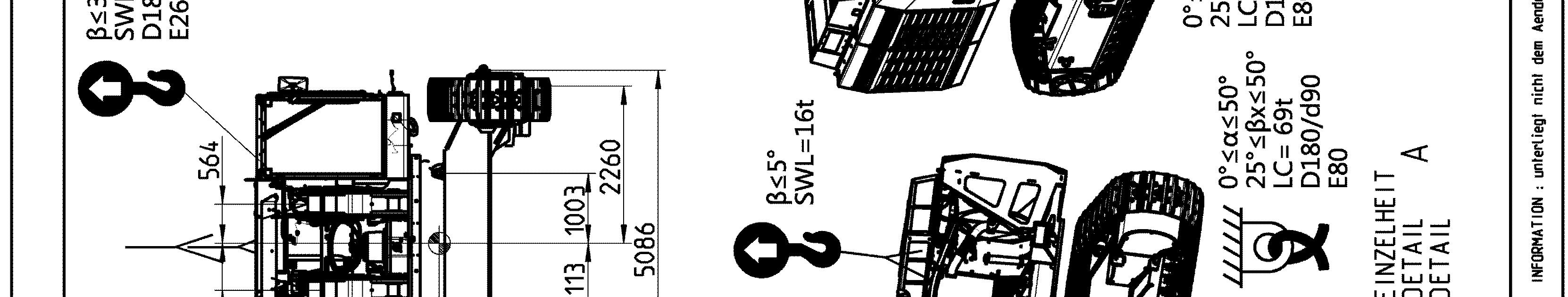
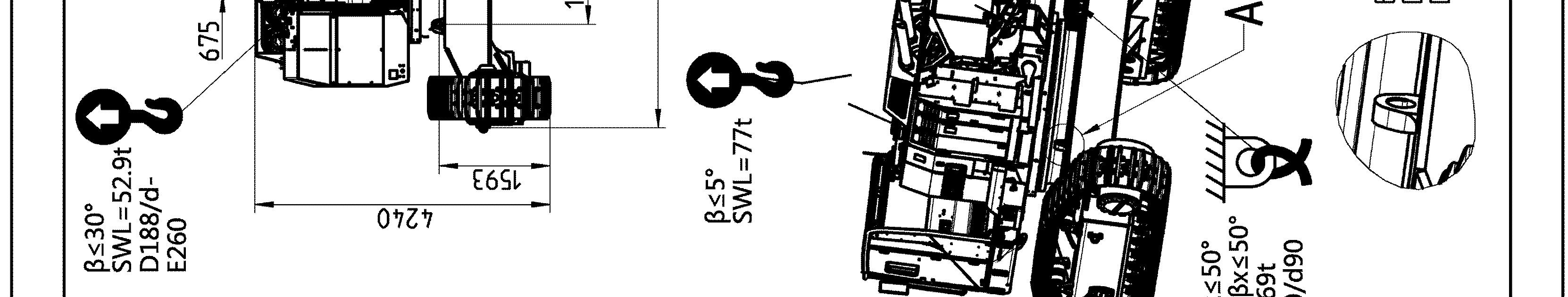
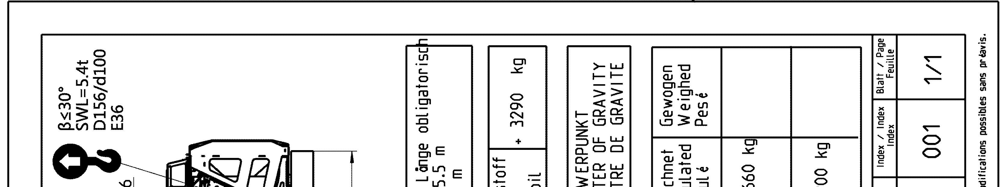
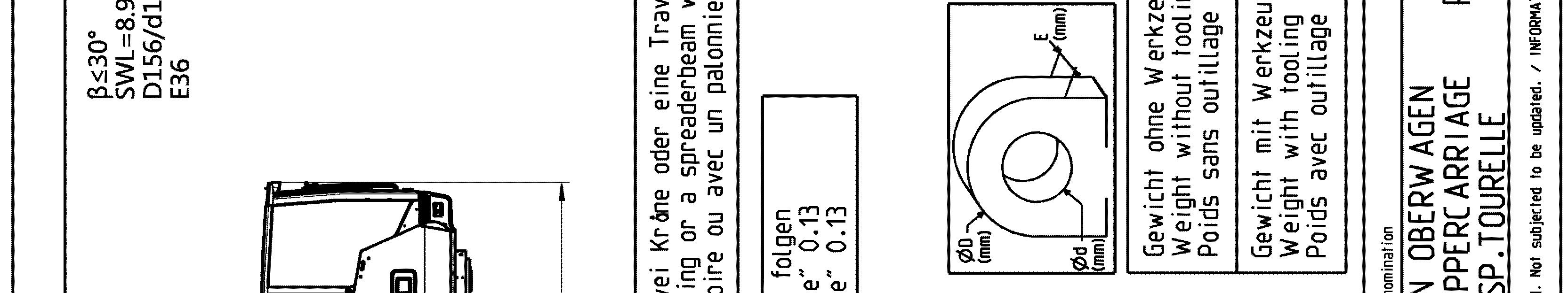
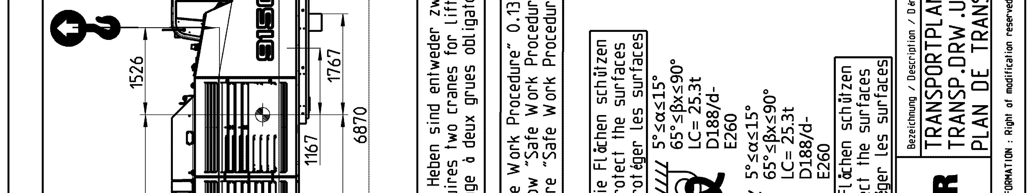
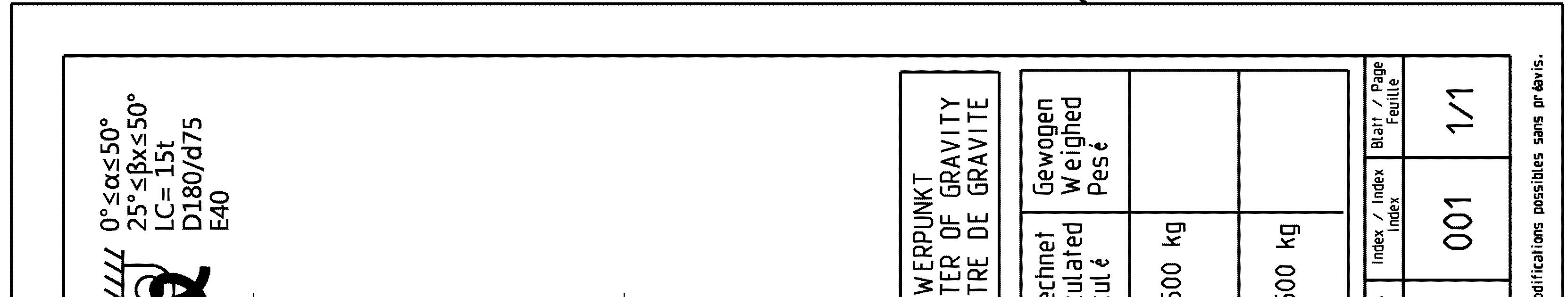
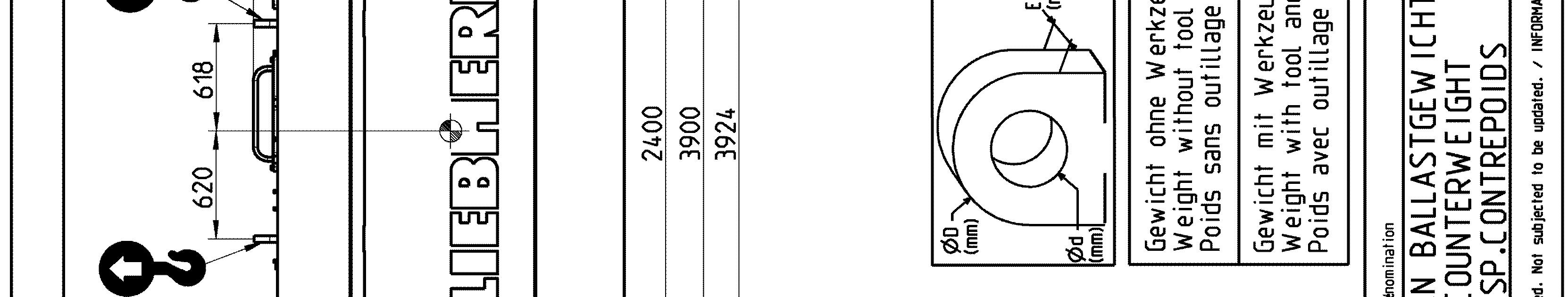
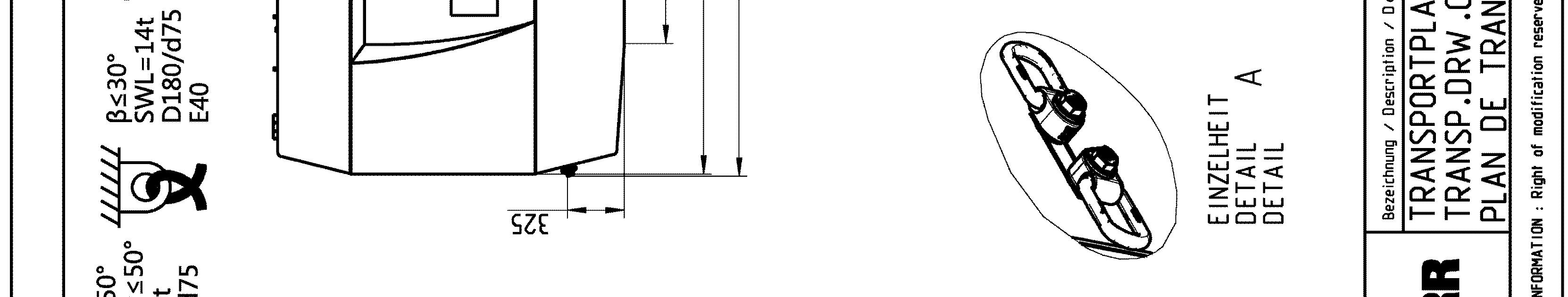
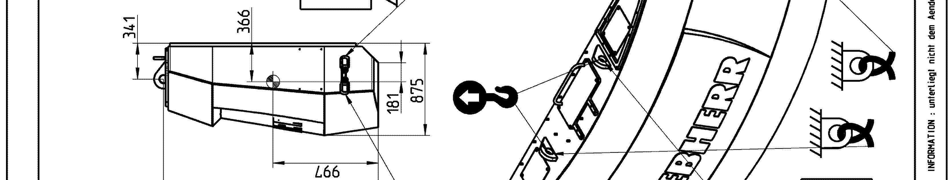
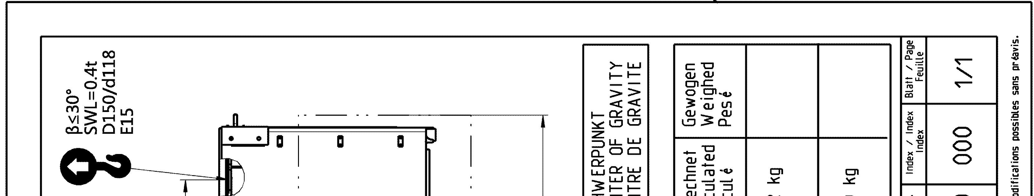
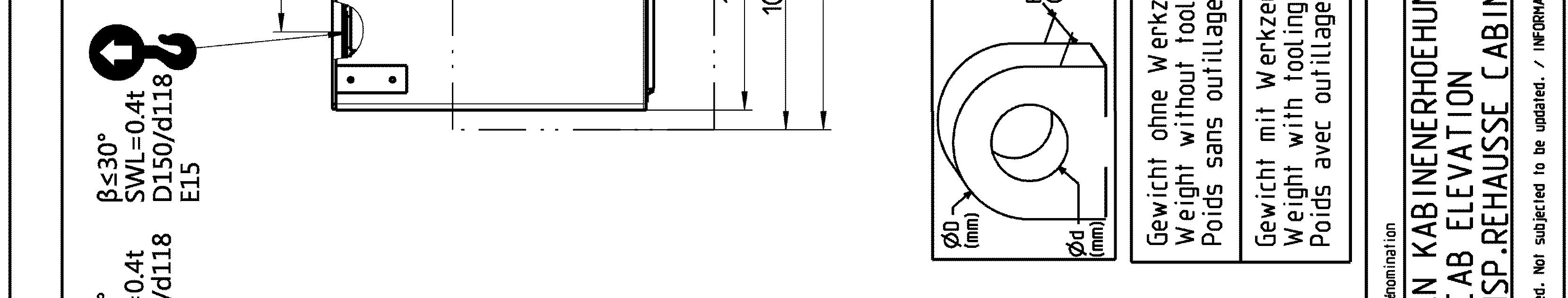
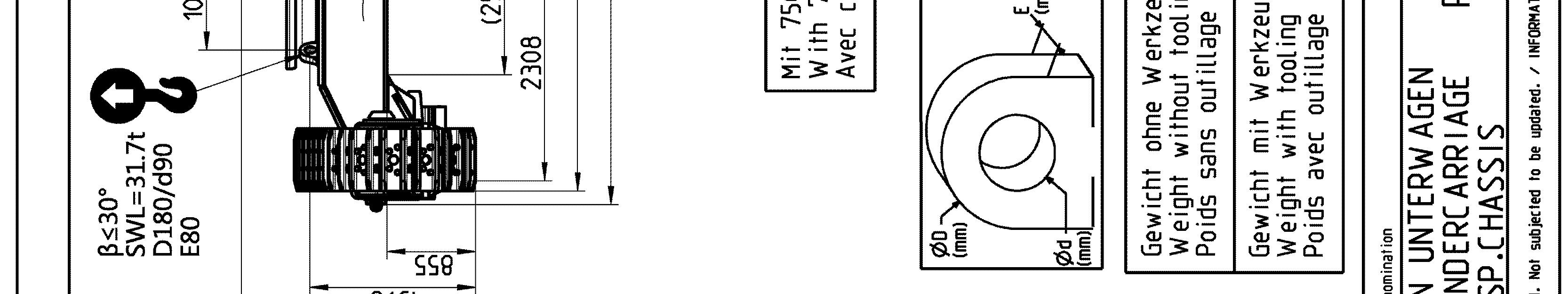
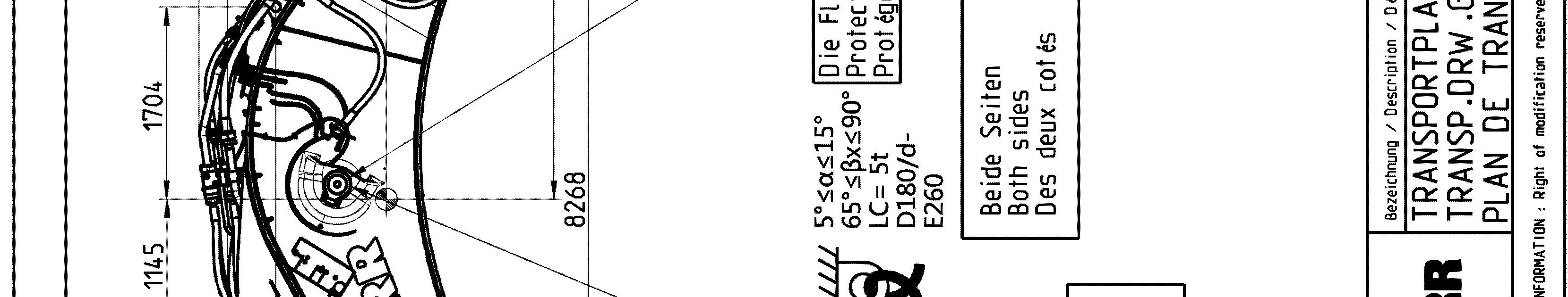
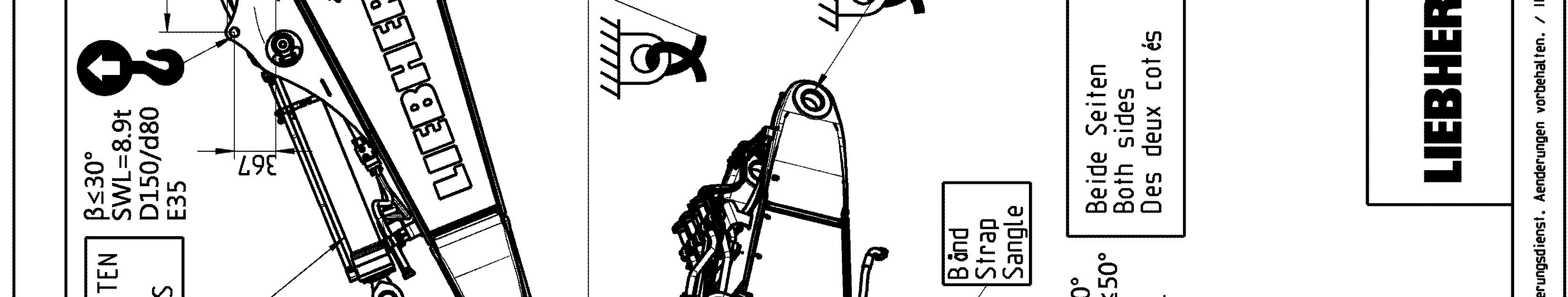
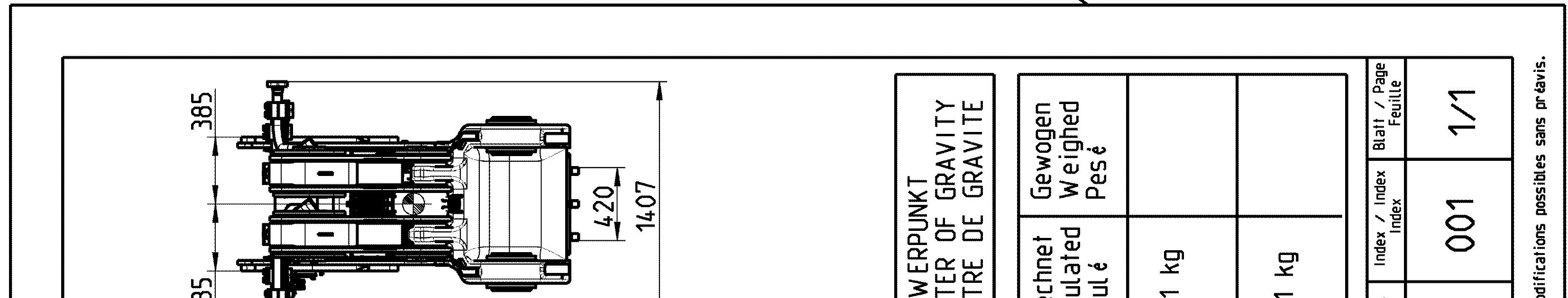
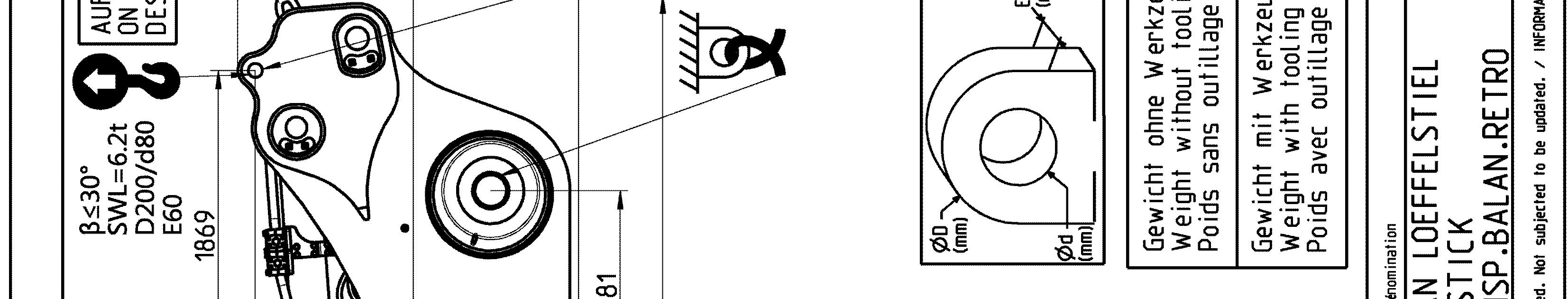
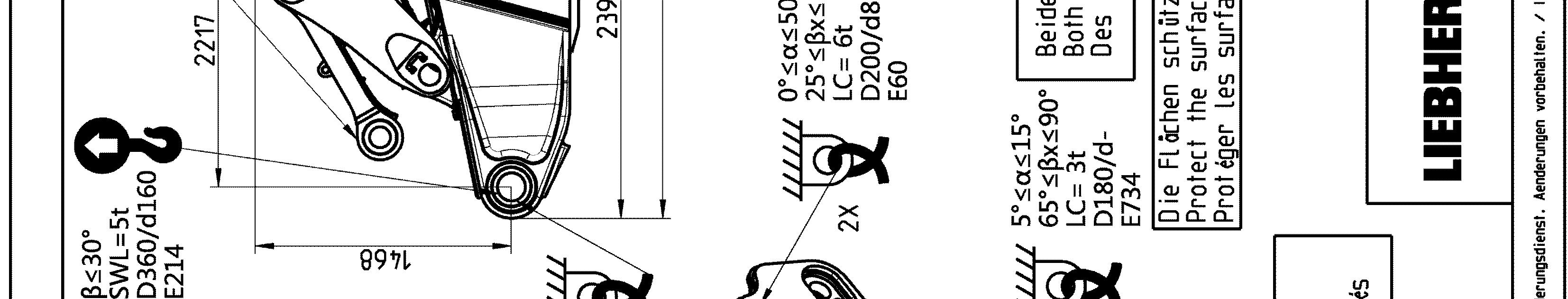
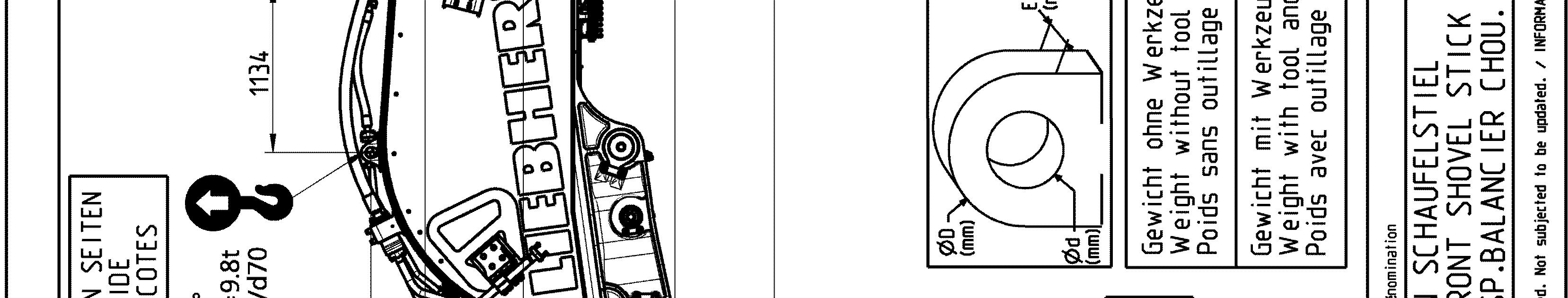
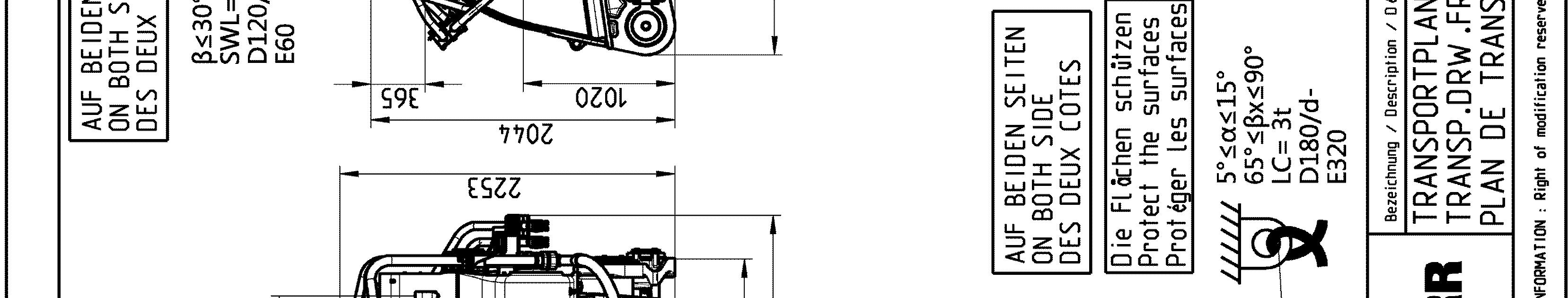
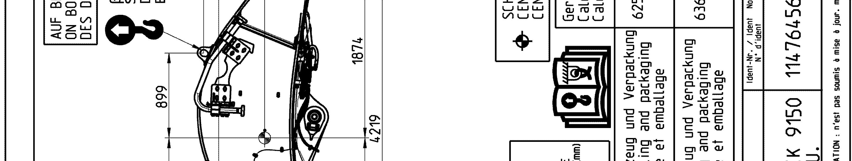
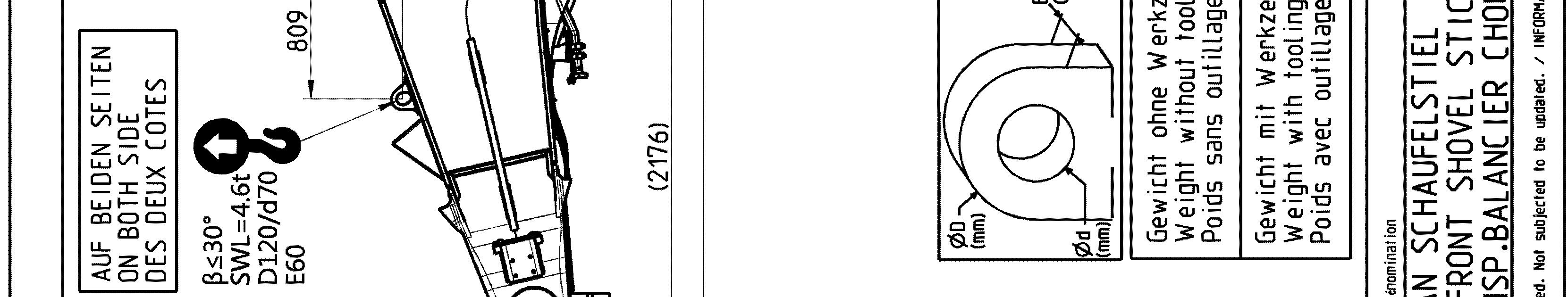
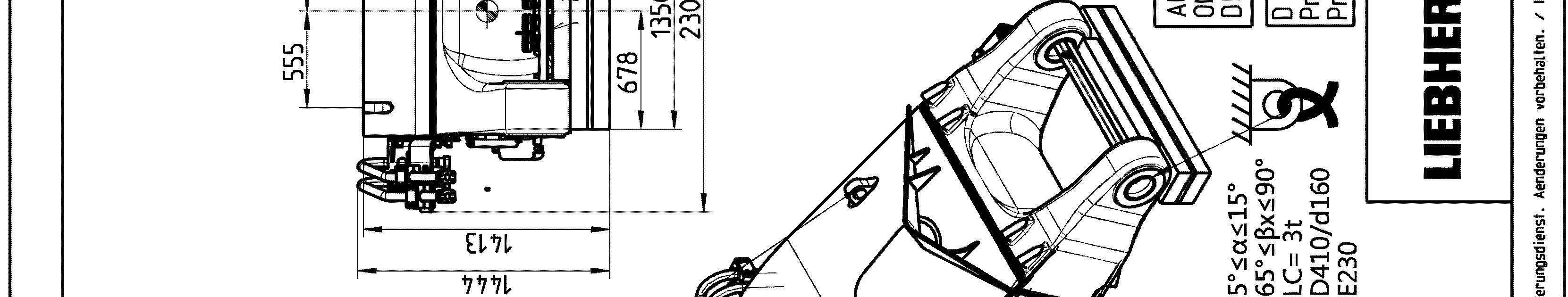
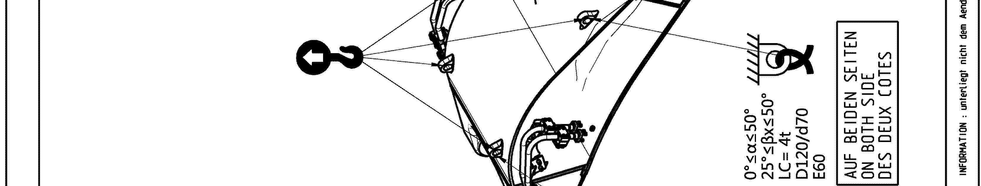
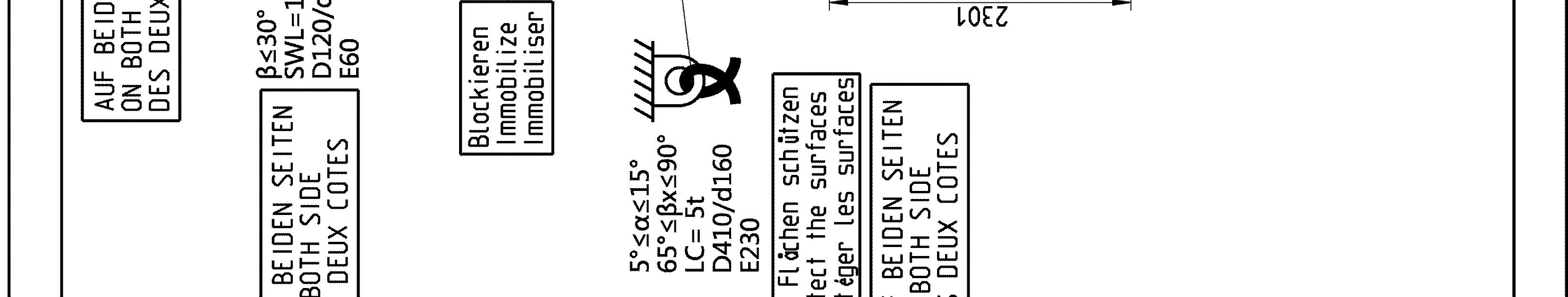
Sticker for lifting and lashing operations
The following sticker is placed next to each transport drawing on the related part and package. It shows rules and precautions which you must obey for transport operations.
The Lashing Capacity LC is the maximum force that the lashing ring can hold in accordance with the angles given on the transport drawing.
The Safe Working Load SWL is the maximum load that the lifting ring can hold in accordance with the angles given on the transport drawing.
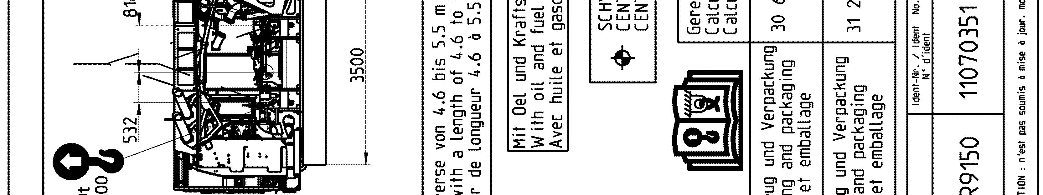
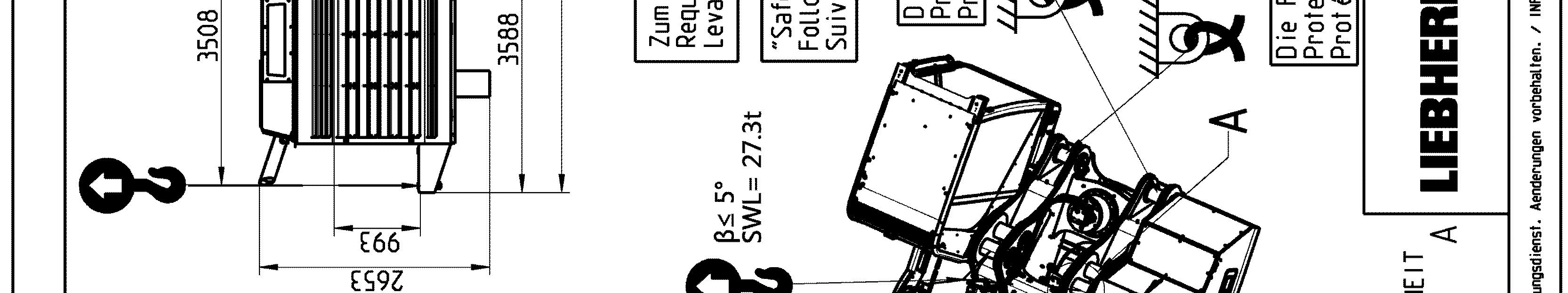
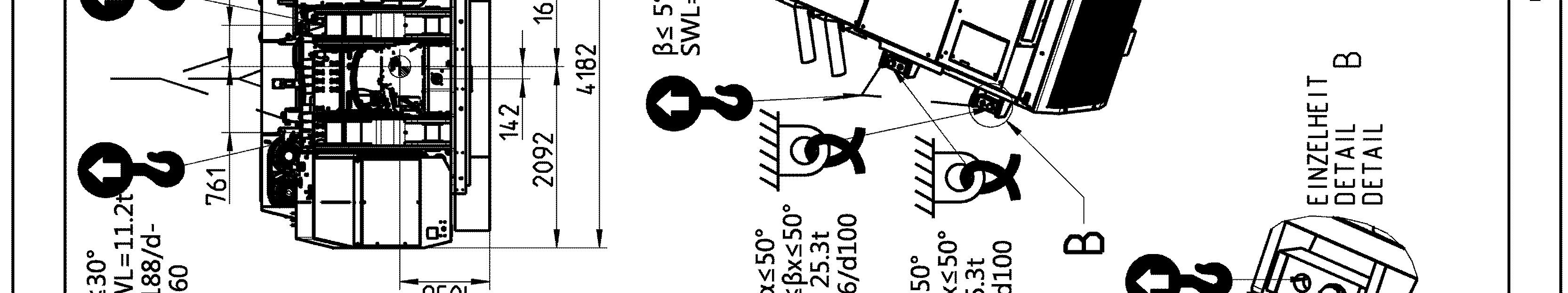
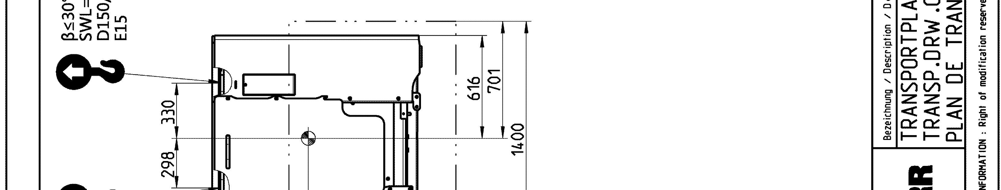
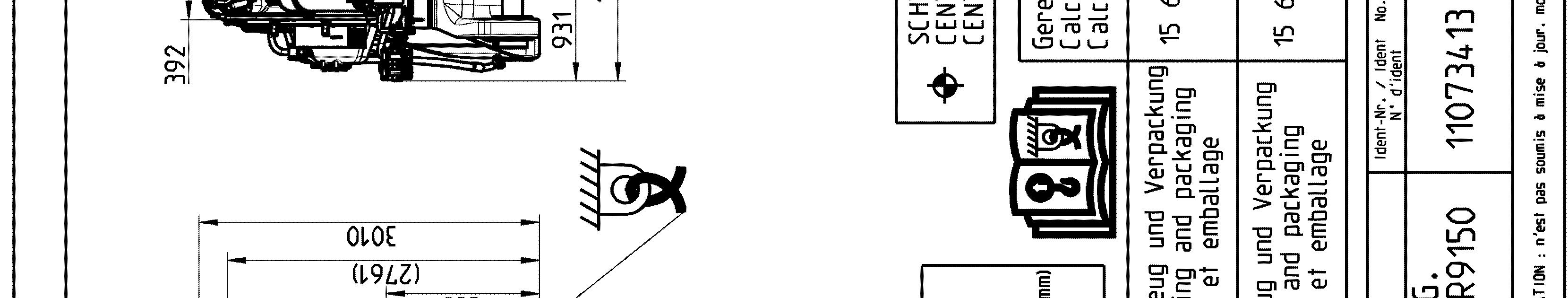
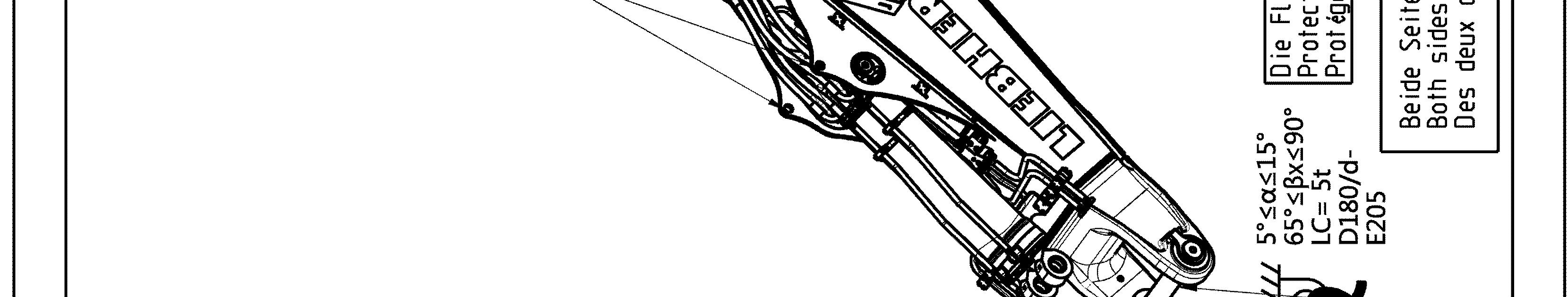
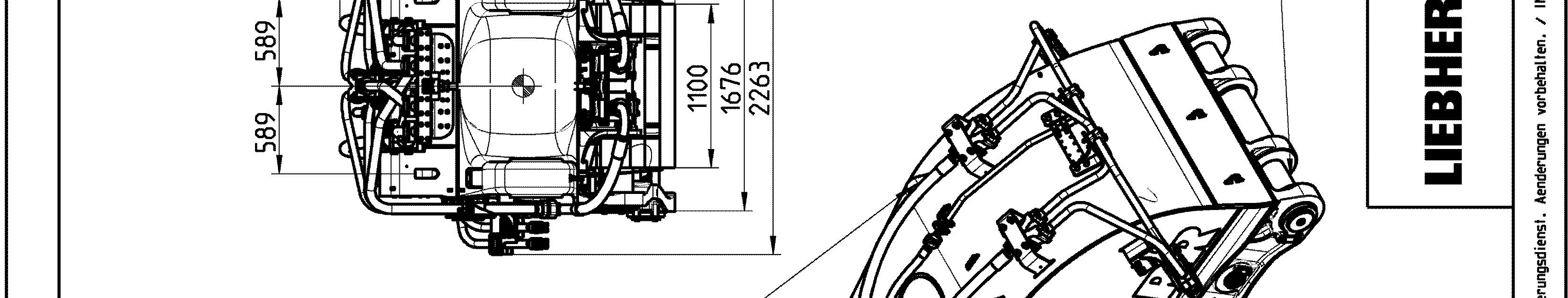
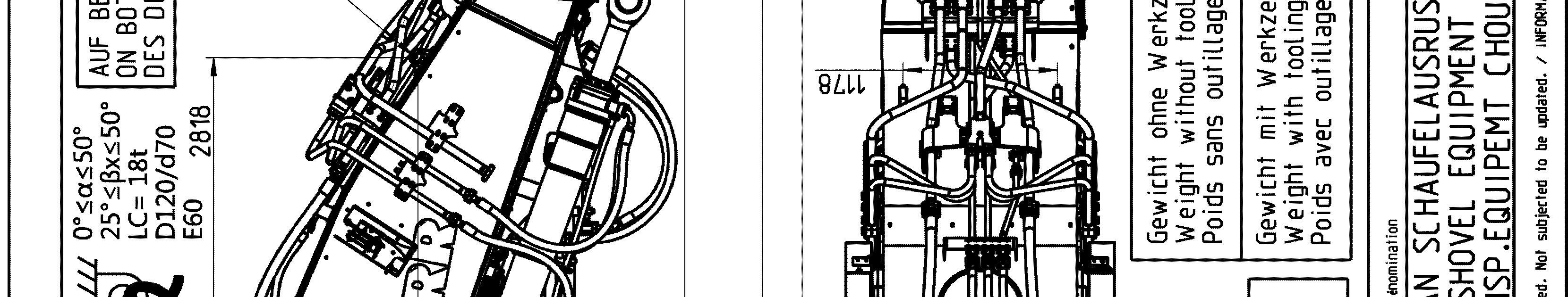
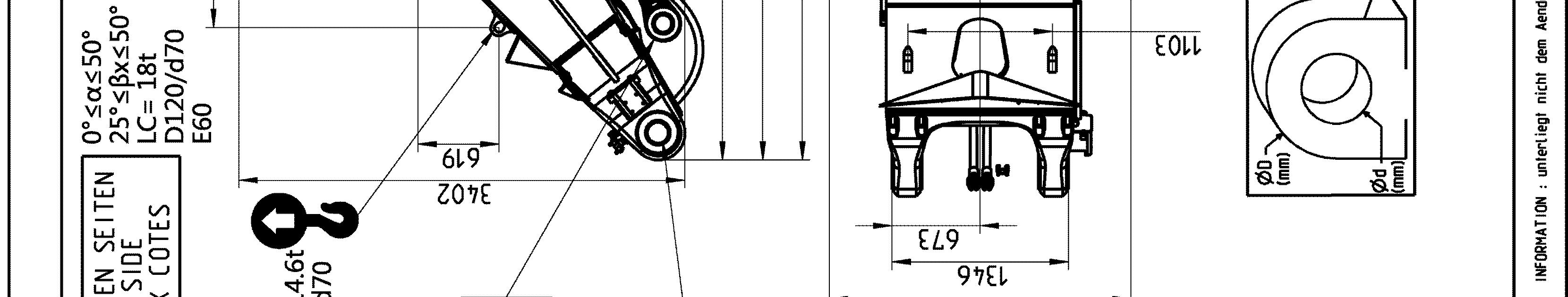
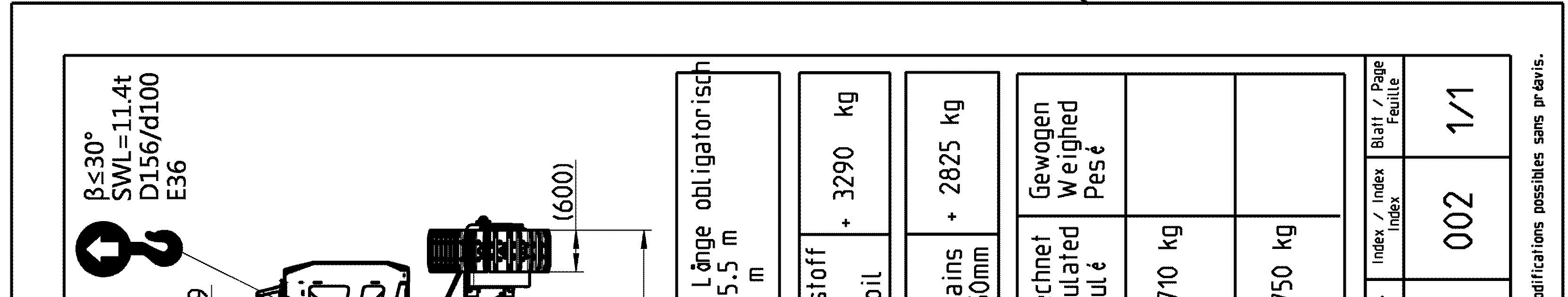
Transport drawings
The following drawings indicate the different lashing and lifting points on the elements of the excavator. Weight (with and without transport tooling and packaging), overall dimensions as well as center of gravity are also given.
The aim of these drawings is to ensure safe operation during transport, handling and storage.
Note!
The lashing and lifting points are indicated on the concerned elements of the excavator by specific labels (see § "Signs on the machine"). To be easily recognized, lifting points are painted in yellow (in red if excavator is yellow) as well.
Danger!
The lifting points given on a transport drawing for an element are designed to lift this element only and nothing else.
Never lift an assembly of several elements by the lifting points of only one of these elements.