8 minute read
2. SERVICING SPECIFICATIONS


3. TIGHTENING TORQUES
Tightening torques of screws, bolts and nuts on the table below are especially specified. (For general use screws, bolts and nuts: See page G-1 0.)
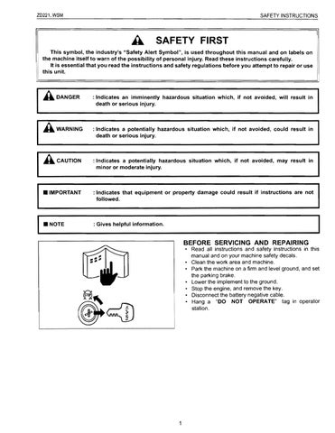
4. CHECKING, DISASSEMBLING AND SERVICING A CAUTION
• To avoid accidental short circuit, be sure to attach the positive cable to the positive terminal before the negative cable is attached to the negative terminal.
• Never remove the battery cap while the engine is running.
• Keep electrolyte away from eyes, hands and clothes. If you are spattered with it, wash it away completely with water immediately.
• Keep open sparks and flames away from the battery at all times. Hydrogen gas mixed with oxygen becomes very explosive
• IMPORTANT
• If the machine is to be operated for a short time without battery (using a slave battery for starting), use additional current (lights) while engine is running and insulate terminal of battery. If this advice is disregarded, damage to alternator and regulator may result.
[1] CHECKING (1) Battery
Battery Voltage
1. Stop the engine and turn the main switch off.
2. Connect the COM (-) lead of the voltmeter to the battery's negative terminal post and the (+) lead to the positive terminal post, and measure the battery voltage.
3. If the battery voltage is less than the factory speCification, check the battery speCific gravity and recharge the battery.
Battery voltage Factory spec. More than 12 V W1015335
3GZAAAK9POO9A
Battery Terminal Connection
1. Turn the main switch on, and turn on the head light.
2. Measure the voltage with a voltmeter across the battery's positive terminal post and the cable terminal, and the voltage across the battery's negative terminal post and the chassis.
3. If the measurement exceeds the factory specification, clean the battery terminal posts and cable clamps, and tighten them firmly.
Potential difference Factory spec. Less than 0.1 V W1015435
3TMABAB9P001 A
3EEABAB1
Battery Specific Gravity
1. Check the specific gravity of the electrolyte in each cell with a hydrometer.
2. When the electrolyte temperature differs from that at which the hydrometer was calibrated, correct the specific gravity reading following the formula mentioned in (Reference).
3. If the specific gravity is less than 1.215 (after it is corrected for temperature), charge or replace the battery.
4. If the specific gravity differs between any two cells by more than 0.05, replace the battery.
• NOTE
• Hold the hydrometer tube vertical without removing it from the electrolyte.
• Do not suck too much electrolyte into the tube.
• Allow the float to move freely and hold the hydrometer at eye level.
• The hydrometer reading must be taken at the highest electrolyte level.
(Reference)
• Specific gravity slightly varies with temperature. To be exact, the specific gravity decreases by 0.0007 with an increase of 1 °C
(0.0004 with an increase of 1°F) in temperature, and increases by 0.0007 with a decreases of 1 °C (0.0004 with a decrease of 1 OF).
Therefore, using 20°C (68 OF) as a reference, the specific gravity reading must be corrected by the following formula:
- Specific gravity at 20°C = Measured value + 0.0007 x (electrolyte temperature - 20 0c)
- Specific gravity at 68 OF = Measured value + 0.0004 x (electrolyte temperature - 68 OF)
(2) Safety Switches
Method of Inspecting Each Control
A defective location can be judge by checking function of each safety switch one by one as shown in the table below.
(Reference)
• Type of Safety Switch
Parking
Motion
PTO
(1)
(2)
* In this part. the safety switch is a position of off. And it is a checked place.
** In this part. the voltage of the terminal of the engine stop solenoid is 0 V.
• How to read meaning from table above. After the engine start, for instance.
1. If the engine does not stop in combination 2 when leaving the seat. the seat safety switch is bad. Moreover, the engine cannot be started without as every sitting on the seat.
2. If the engine starts with the parking brake released at combination
3, the parking brake safety switch is bad.
3. If the engine starts in combination 4 when the PTO lever is ON position, the PTO lever switch is bad.
4. If the engine starts in combinations 5 and 6 when the motion control lever is a Operating position, the motion control lever safety switch is bad. Moreover. the engine stops if the parking pedal is not released within two seconds after the engine starts.
(3) Main Switch
Main Switch Continuity
1) Main Switch Key at OFF Position
1. Set the main switch OFF position.
2. Measure the resistance with an ohmmeter across the B terminal and the ACC terminal, B terminal and ST terminal, B terminal and G terminal.
3. If infinity is not indicated, the contacts of the main switch are faulty. 3XVAAAB9P027 A
Resistance
B terminal - ACC terminal Infinity B terminal - ST terminal
B terminal G terminal
2) Main Switch Key at ON Position
1. Set the main switch ON position.
2. Measure the resistance with an ohmmeter across the B terminal and the ACC terminal.
3. If 0 ohm is not indicated, the B ACC contact of the main switch are faulty.
I Resistance I B terminal - ACC terminal I a .0
3) Main Switch Key at PREHEAT Position
1. Set and hold the main switch key at the PREHEAT position.
2. Measure the resistance with an ohmmeter across the B terminal and the G terminal, and measure the resistance across the B terminal and the ACC terminal.
3. If 0 ohm is not indicated, these contacts of the main switch are faulty.
I B terminal -G terminal
I B terminal - ACC terminal
4) Main Switch Key at START Position
1. Set and hold the main switch key at the START position.
2. Measure the resistance with an ohmmeter across the B terminal and the G terminal, across the B terminal and the ST terminal, and across the B terminal and the ACC terminal.
3. If 0 ohm is not indicated, these contacts of the main switch are faulty.
Resistance B terminal -G terminal on B terminal - ST terminal B terminal - ACC terminal (1)
W10136580
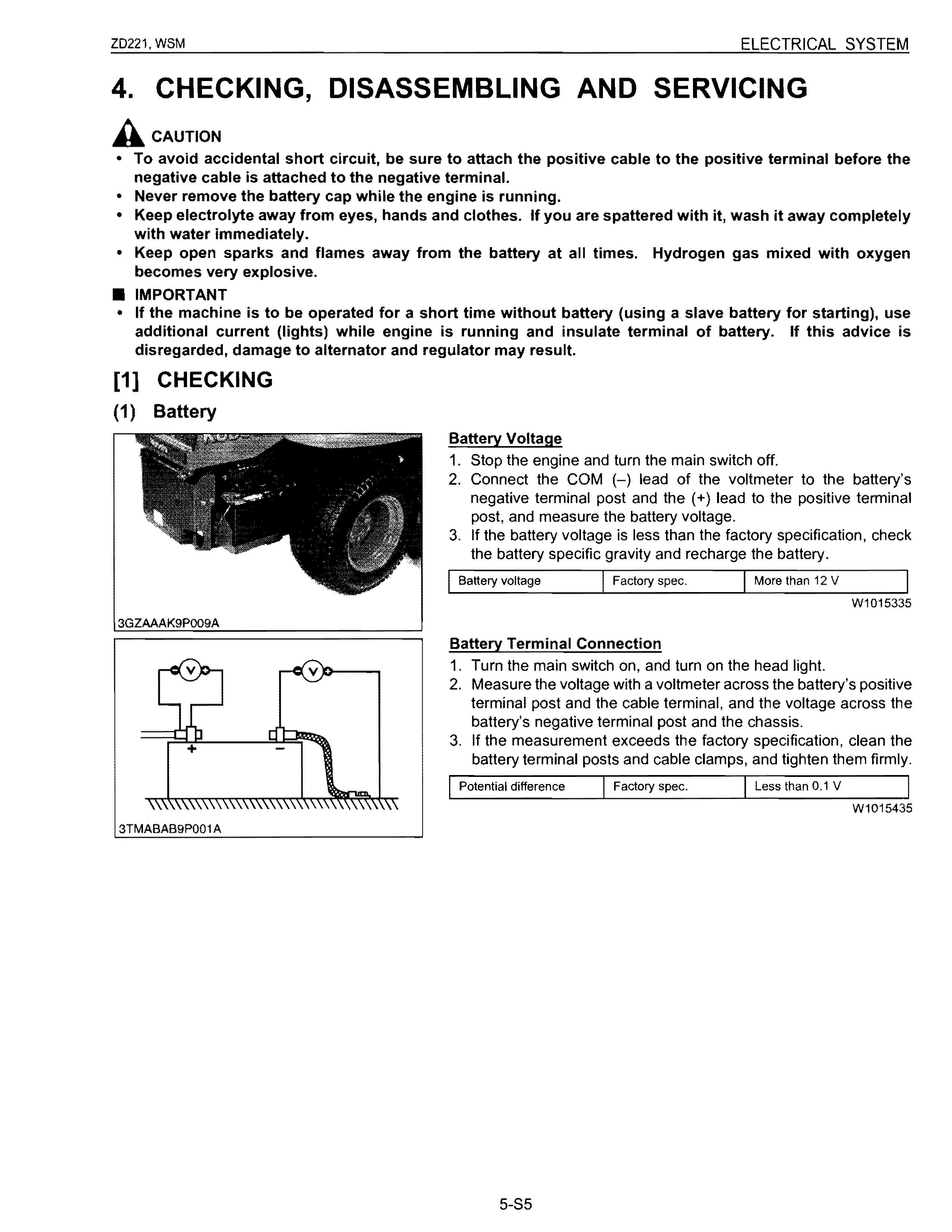
(4) Starter
Motor Test A CAUTION
• Secure the starter to prevent it from jumping up and down while testing the motor.
1. Disconnect the battery negative cable from the battery.
2. Disconnect the battery positive cable and the leads from the starter.
3. Remove the starter from the engine.
4. Disconnect the connecting lead (2) from the starter C terminal (1 ).
5. Connect a jumper lead from the connecting lead (2) to the battery positive terminal post.
6. Connect a jumper lead momentarily between the starter motor housing and the battery negative terminal post.
7. If the motor does not run, check the motor.
(1) C Terminal (2) Connecting Lead
Magnet Switch Test (Pull-in, Holding Coils)
• NOTE
W1018134
• Each test should be carried out for a start time (3 to 5 seconds), and at half of the rated voltage (6V)
1) Checking Pull-in Coil
1. Connect jumper lead from the battery's negative terminal post to the C terminal.
2. The plunger should be attached strongly when a jumper lead is connected from the battery positive terminal to the S terminal.
2) Checking Holding Coil
1. Connect jumper leads from the battery's negative terminal post to the body and the battery's positive terminal post to the S terminal.
2. Push the plunger in by hand and release it. Then, the plunger should remain being attracted.
W1018490
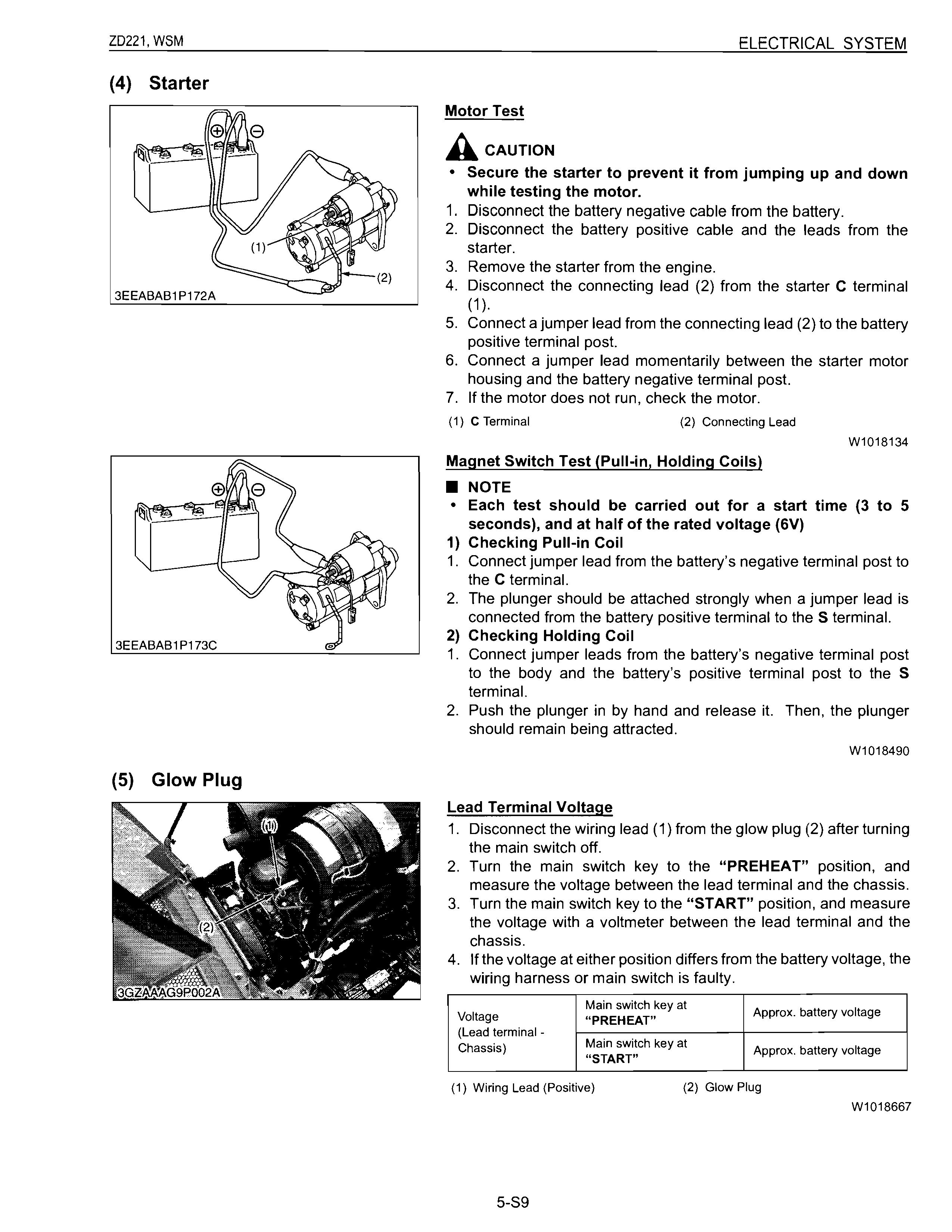
(5) Glow Plug
Lead Terminal Voltage
1. Disconnect the wiring lead (1) from the glow plug (2) after turning the main switch off.
2. Turn the main switch key to the "PREHEAT" position, and measure the voltage between the lead terminal and the chassis.
3. Turn the main switch key to the "START" position, and measure the voltage with a voltmeter between the lead terminal and the chassis.
4. If the voltage at either position differs from the battery voltage, the wiring harness or main switch is faulty.
(1)
W1018667
3TMABAB9P012A
(6) Safety Switch
Glow Plug Continuity
1. Disconnect the lead from the glow plugs.
2. Measure the resistance with an ohmmeter between the glow plug terminal and the chassis.
3. If 0 ohm is indicated. the screw at the tip of the glow plug and the housing are short-circuited.
4. If the factory specification is not indicated, the glow plug is faulty.
Glow plug resistance Factory spec. Approx. 0.9 n
Safety Switch Continuity
1. Remove the safety switch leads.
2. Connect the circuit tester to the safety switch leads.
3. Measure the resistance between leads.
4. If the safety switch is defective, replace it.
Resistance (Across I When switch push is on switch terminal)
· Motion control lever When switch push is Infinity
· PTO lever released
· Operator seat
Resistance (Across When actuator is pushed Infinity switch terminal) Parking brake When actuator is released on pedal (1) Safety Switch
W1018992
W1019187
(7) Fuel Pump
Connector Voltage
1. Disconnect the 2P connector from the fuel pump.
2. Turn the main switch key to the "ON" position, and measure the voltage with a voltmeter between the connector terminals.
3. If the voltage differs from the battery voltage, the wiring harness or main switch is faulty.
Between connector
Voltage Approx. battery voltage terminals W1019413
3TVAAAC9P003A
Fuel Pump Continuity
1. Disconnect the 2P connector from the fuel pump.
2. Check the continuity between the connector terminals with an ohmmeter.
3. If it does not conduct, the fuel pump is faulty.
3TVAAAC9P004A
(8) Engine Stop Solenoid
I----t I------'
12V
Engine Stop Solenoid Test
1. Disconnect the connector from the engine stop solenoid.
2. Remove the engine stop solenoid from the engine.
3. Connect the jumper leads from the battery positive terminal to the connector, and from the battery negative terminal to the engine stop solenoid body.
4. If the solenoid plunger is not attracted, the engine stop solenoid is faulty.
(1) White (2) Black W1019658
3TAAAAB9P033B
! 3GZAAAG9P004A
(9) Charging System
No-load Dynamo Output
1. Disconnect the lead wires from the dynamo.
2. Start the engine and operate the dynamo at the rated speed.
3. Measure the output voltage with a volt meter.
4. If the measurement is not within the specified values, replace the dynamo.
No-load output Factory spec. AC 20 V or more
Regulation Voltage
Acaution
W1048417
• To avoid personal injury, do not touch the rotating or hot parts while the engine is running.
• NOTE
• Before performing this checking. make sure that the no-load dynamo output is proper.
• Complete the charging circuit with fully charged battery.
1. Rum the engine at the rated speed.
2. Keeping the coupler (2) of regulator being connected, measure the voltage with a volt meter (5) across the terminal blue (a) and terminal blue (c). (Refer to figure (A).)
3. If the measurement is not within the specified value, replace the wire harness between the dynamo (4) and regulator (1).
4. If the measurement is within the specified value, measure the voltage with a volt meter (6) across the terminal red (f) and chassis. (Refer to figure (B).)
5. If the measurement is not within specified value, replace the regulator (1).
W1015722
(10) Lighting System
Charge Lamp (Charging Circuit)
1. Remove the under panel.
2. Disconnect the 6P connector from the regulator after turning the main switch OFF.
3. Turn the main switch ON and connect a jumper lead from the wiring harness connector terminal (Black) to the chassis.
4. If the charge lamp does not light, the wiring harness or fuse is faulty.
(1) Regulator (a) From Charge Lamp
Engine Oil Pressure Lamp
W1024567
1. Disconnect the lead from the engine oil pressure switch after turning the main switch OFF.
2. Turn the main switch ON and connect a jumper lead from the lead to the chassis.
3. If the engine oil pressure indicator lamp does not light, the wiring harness is faulty.
(1) Engine Oil Pressure Switch (a) From Oil Pressure Lamp
W1024686
Engine Oil Pressure Switch Continuity
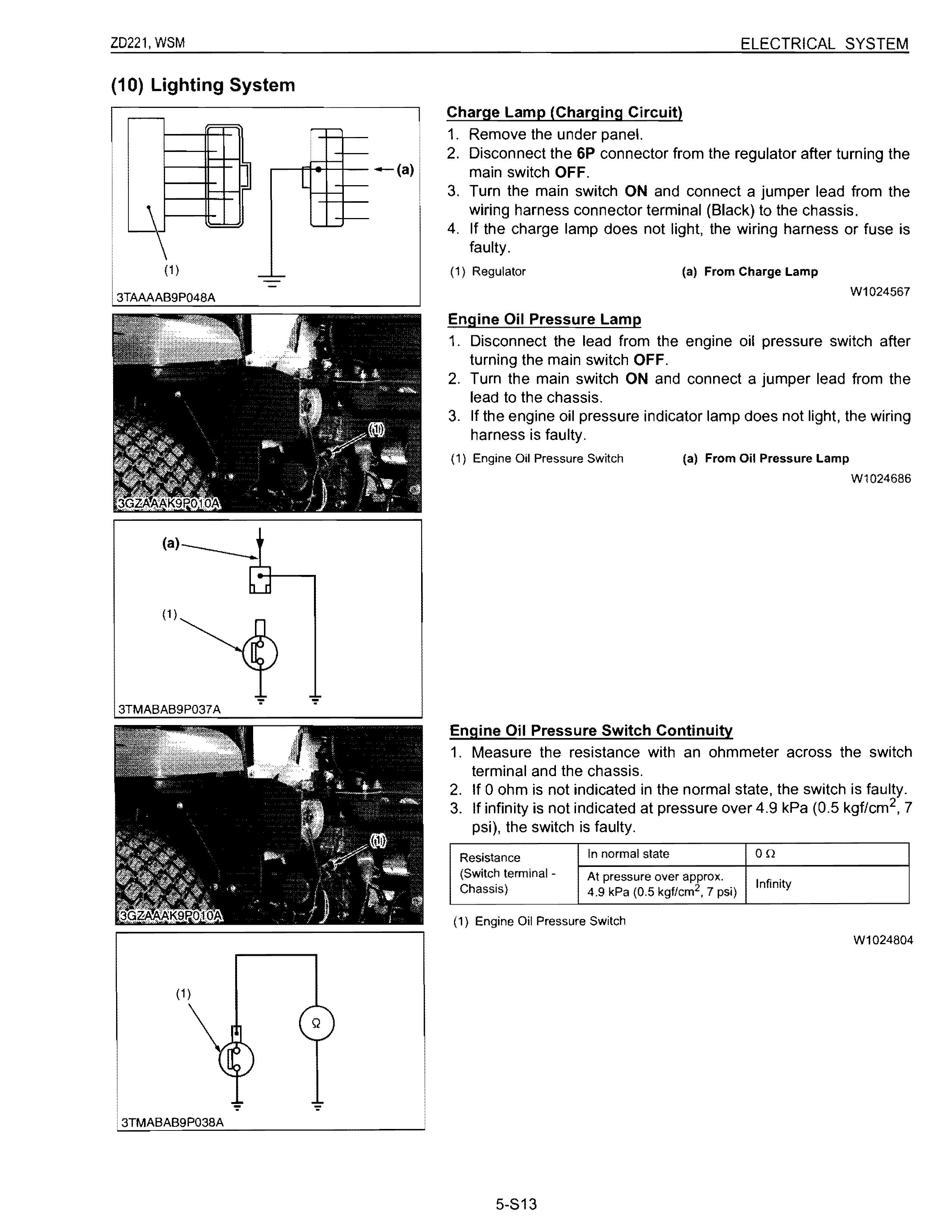
1. Measure the resistance with an ohmmeter across the switch terminal and the chassis.
2. If a ohm is not indicated in the normal state, the switch is faulty.
3. If infinity is not indicated at pressure over 4.9 kPa (0.5 kgf/cm 2 , 7 psi), the switch is faulty.
Resistance In normal state Ion
(Switch terminal Chassis) At pressure over approx. 4.9 kPa (0.5 kgf/cm 2 , 7 psi)
(1) Engine Oil Pressure Switch
IIfi 't n In! y
W1024804