3 minute read
2. STARTING SYSTEM


When the main switch is turned to the PREHEAT position, the terminal 30 is connected to the terminals 19 and AC. The glow plugs become red-hot, and the preheat indicator lamp also lights on while preheating.
When the main switch is then turned to the START position with the safety switches on, the terminal 30 is connected to the terminals 50 and AC. Consequently, battery current flows to the starter motor and start the engine.
The main switch automatically returns to the ON position, the terminal 30 is connected only to the terminal AC, thereby causing the starting circuit to be opened, stopping the starter motor.
When the main switch turned from the ON position to the OFF position, the fuel cut-off solenoid moves the fuel injection pump control rack to the "No Fuel Injection" position and stop the engine.
Relay (1) basically consists of relay winding (2) and mechanical contact points (9).
Current flowing from switch to relay winding (5) cause "ON (Close)" or "OFF (Open)" of mechanical contact pOints (9).
When current is applied to the winding (energized) (10), a magnetic field pushes the contact lever (8) and normally open terminal is connected.
Function of relay (1) is to control current to be controlled in circuit from distant place (switch location place).
Another function of relay (1) is to control large current by small current.
function of each relay are as follows.
• Relay 1 : Relay to horn (overheat alarm relay)
• Relay 2 : Relay to start engine (starter relay)
• Relay 3 : Relay to stop engine (solenoid relay)
(1) Relay (6) 86 Terminal
(2) 85 Terminal (7) 30 Terminal
(3) 87 Terminal (8) Contact Lever
(4) 87 Terminal (9) Mechanical Contact Points
(5) Relay Winding (10) Winding (Energized)
W1016715
(1) Housing
(2) Magnetic Switch
(3) Overrunning Clutch
(4) Drive Lever
(5) Internal Gear
(6) Gear Shaft
(7) Planetary Gear
(8) Armature Shaft
(9) Yoke
(10) Brush Holder
(11) Rear End Holder
W1012893
3TAAAAD9P022B
The reduction system is used planetary gears, and the speed of gear shaft (6) is reduced to approximately one fifth of the armature shaft (8).
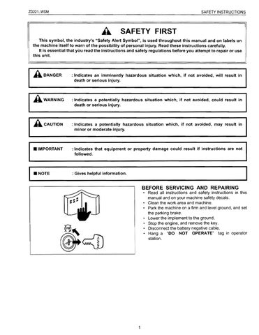
This plug is a two-material type QGS (Quick Glow System) for quick temperature rise, and has selfcontrolling function as well as excellent durability.
The heater (4) connected in series to the heater (3), which also functions as the resistor, is incorporated in the sheath tube (1) of the super glow plug.
The resistance of this heater (3) cum resistor is small when the temperature is low, while the resistance becomes large when the temperature rises.
Therefore, because sufficient current is flown to the heater (4) during the initial period of energization, the temperature rises quickly and the resistance grows with the rise in the temperature of the resistor, the flowing current is reduces to prevent the heater (4) from being heated.
The ignition point is in the area of 2 to 3 mm (0.079 to 0.118 in.) from the tip of the plug in order to reduce its projection into the combustion chamber.
(1) Sheath Tube (a) Glow Plug Temperature (0C)
(2) Insulation Powder (b) Current (A)
(3) Heater also functioning as a (c) Time (Sec.) Resistor
(4) Heater
(5) Super Glow Plug
(6) Conventional Quick-heating type Glow Plug
(7) Glow Plug Current
Switch
W1013021
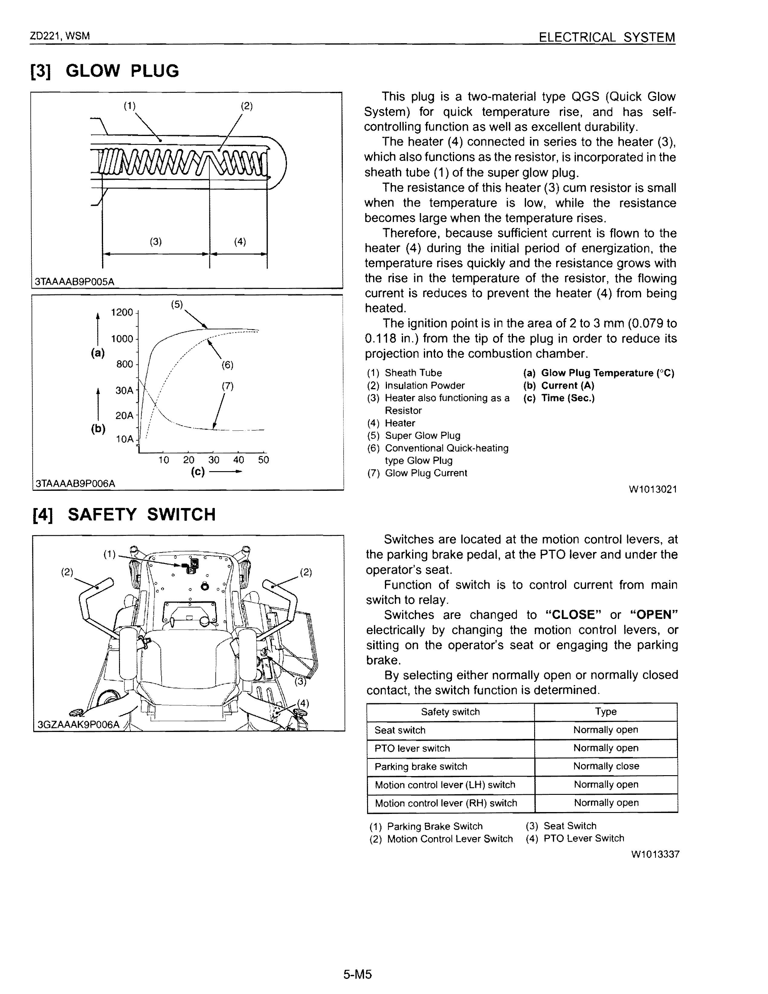
Switches are located at the motion control levers, at the parking brake pedal, at the PTa lever and under the operator's seat.
Function of switch is to control current from main switch to relay.
Switches are changed to "CLOSE" or "OPEN" electrically by changing the motion control levers, or sitting on the operator's seat or engaging the parking brake.
By selecting either normally open or normally closed contact, the switch function is determined.
Safety switch Type
Seat switch
PTO lever switch
Normally open
Normally open
Parking brake switch Normally close
Motion control lever (LH) switch Normally open
Motion control lever (RH) switch Normally open
(1) Parking Brake Switch (3) Seat Switch (2) Motion Control Lever Switch (4) PTO Lever Switch W1013337
[5] FUEL PUMP
3TAAAAB9P008A
[6] ENGINE STOP SOLENOID
An electro magnetic fuel pump uses a transistor that causes the pump to start pumping fuel when the main switch is turned to the "ON" position.
Therefore, fuel is supplied to the fuel injection pump regardless of engine speed. This pump is driven by the battery. It can therefore be operated even with the engine being stopped.
A: Inlet 8: Outlet
W1013306 a: ON [A] ZD321 , ZD323 b: OFF [8] ZD326, ZD331
Controller is provided to actuate the engine stop solenoid approx. 10 seconds to stop after the main switch is turned from ON position to OFF position.
Flowing of the battery current into the coil while the controller's timer works attracts the plunger to actuate the stop lever or control rack of the injection pump. When the battery current stops, the plunger is returned to the original position by the spring.
W1013394
3TAAAAB9P009A