8 minute read
4. CHECKING, DISASSEMBLING AND SERVICING [1]

![2. TRAVELLING SYSTEM [1] HYDROSTATIC TRANSMISSION](https://assets.isu.pub/document-structure/230324105859-76e47f13a5ec6f7125364bf56105590b/v1/3e2ef2845ca4b179b1af299dd2d67c41.jpeg)
Checking And Adjusting
Checking Neutral of HST
1. Park machine safely.
2. Set the motion control levers are in the NEUTRAL position.
3. Move the PTO lever to OFF position and apply the parking brake.
4. With the operator on the seat and start the engine.
5. Move the throttle lever to Max. speed position.
6. Release the parking brake.
7. Check the drive wheels. the wheel should not move.
8. If movements is noted. perform adjustment as follows.
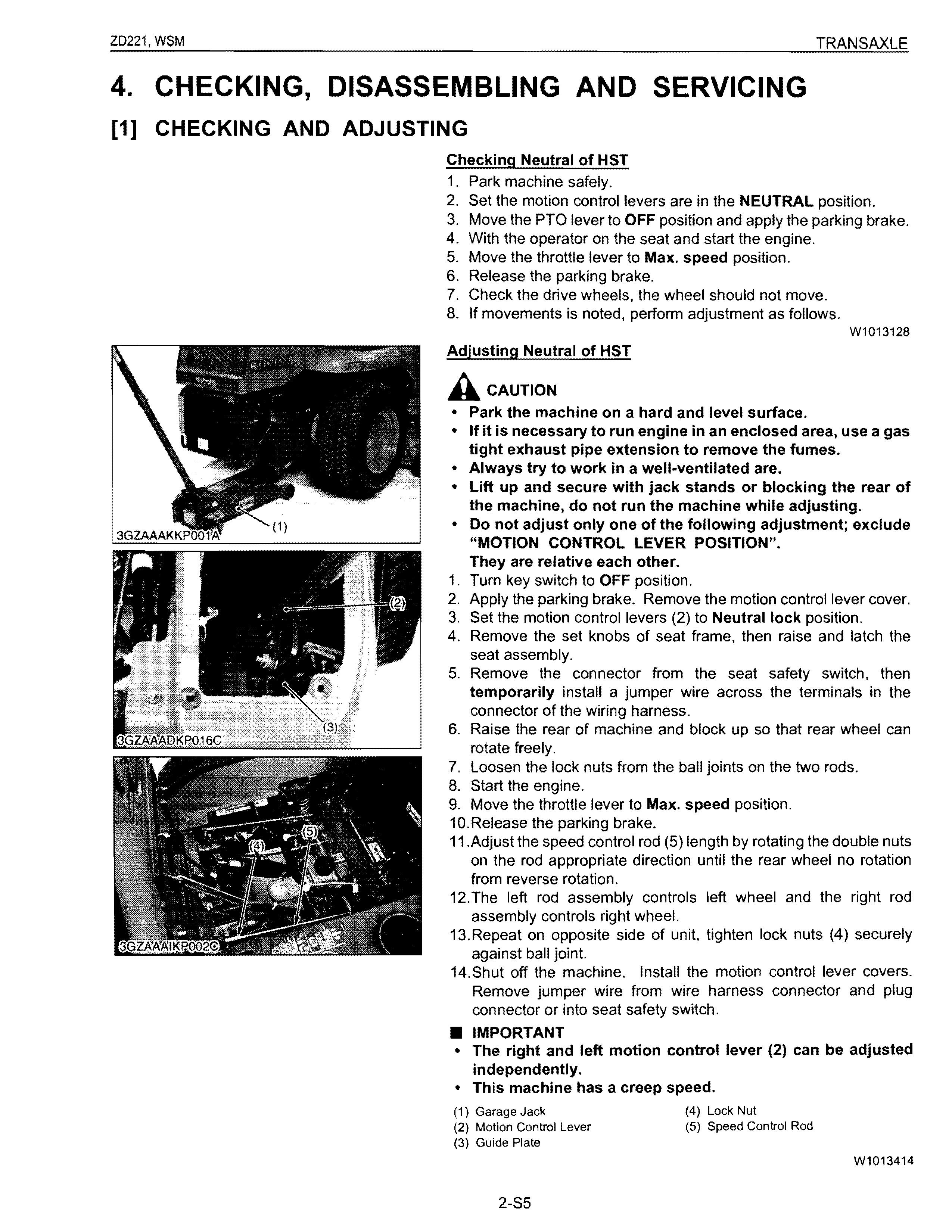
Adjusting Neutral of HST
Acaution
• Park the machine on a hard and level surface.
W1013128
• If it is necessary to run engine in an enclosed area, use a gas tight exhaust pipe extension to remove the fumes.
• Always try to work in a well-ventilated are.
• Lift up and secure with jack stands or blocking the rear of the machine, do not run the machine while adjusting.
• Do not adjust only one of the following adjustment; exclude "MOTION CONTROL LEVER POSITION". They are relative each other.
1. Turn key switch to OFF position.
2. Apply the parking brake. Remove the motion control lever cover.
3. Set the motion control levers (2) to Neutral lock position.
4. Remove the set knobs of seat frame. then raise and latch the seat assembly.
5. Remove the connector from the seat safety switch. then temporarily install a jumper wire across the terminals in the connector of the wiring harness.
6. Raise the rear of machine and block up so that rear wheel can rotate freely.
7. Loosen the lock nuts from the ball joints on the two rods.
8. Start the engine.
9. Move the throttle lever to Max. speed position.
10.Release the parking brake.
11.Adjust the speed control rod (5) length by rotating the double nuts on the rod appropriate direction until the rear wheel no rotation from reverse rotation.
12.The left rod assembly controls left wheel and the right rod assembly controls right wheel.
13.Repeat on opposite side of unit, tighten lock nuts (4) securely against ball joint.
14.Shut off the machine. Install the motion control lever covers. Remove jumper wire from wire harness connector and plug connector or into seat safety switch
• IMPORTANT
• The right and left motion control lever (2) can be adjusted independently.
• This machine has a creep speed.
Checking Creep in Forward A CAUTION
• Park the machine on a hard and lever surface.
• If it is necessary to run engine in an enclosed area, use a gas tight exhaust pipe extension to remove the fumes.
• Always try to work in a well-ventilated area.
• Lift up and secure with jack stands or blocking the rear of the machine, do not run the machine while adjusting.
• Do not adjust only one of the following adjustment; exclude "MOTION CONTROL LEVER POSITION". They are relative each other.
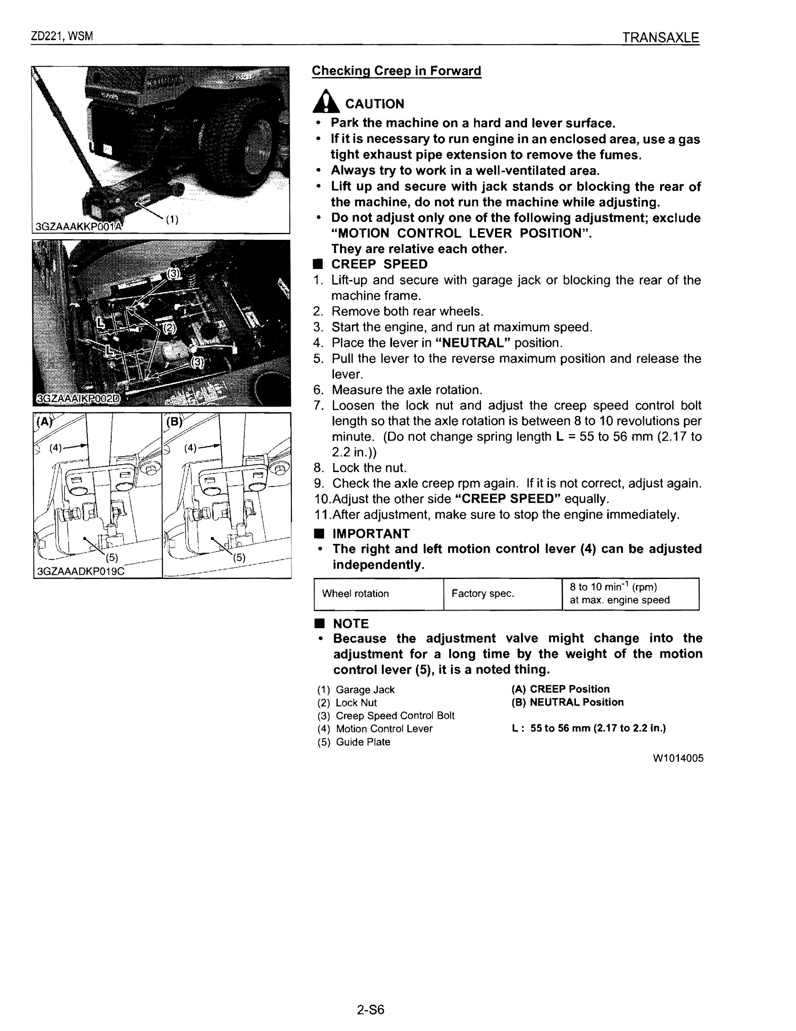
• CREEP SPEED
1. Lift-up and secure with garage jack or blocking the rear of the machine frame.
2. Remove both rear wheels.
3. Start the engine, and run at maximum speed.
4. Place the lever in "NEUTRAL" position.
5. Pull the lever to the reverse maximum position and release the lever.
6. Measure the axle rotation.
7. Loosen the lock nut and adjust the creep speed control bolt length so that the axle rotation is between 8 to 10 revolutions per minute. (Do not change spring length L = 55 to 56 mm (2.17 to 2.2 in.»
8. Lock the nut.
9. Check the axle creep rpm again. If it is not correct, adjust again.
10.Adjust the other side "CREEP SPEED" equally.
11.After adjustment, make sure to stop the engine immediately.
• IMPORTANT
• The right and left motion control lever (4) can be adjusted independently. 8 to 10 min" (rpm)
Wheel rotation Factory spec. at max. engine speed
• NOTE
• Because the adjustment valve might change into the adjustment for a long time by the weight of the motion control lever (5), it is a noted thing.
(1) Garage Jack
(2) Lock Nut
(3) Creep Speed Control Bolt
(A) CREEP Position
(8) NEUTRAL Position
(4) Motion Control Lever L: 55 to 56 mm (2.17 to 2.2 in.)
(5) Guide Plate
W1014005
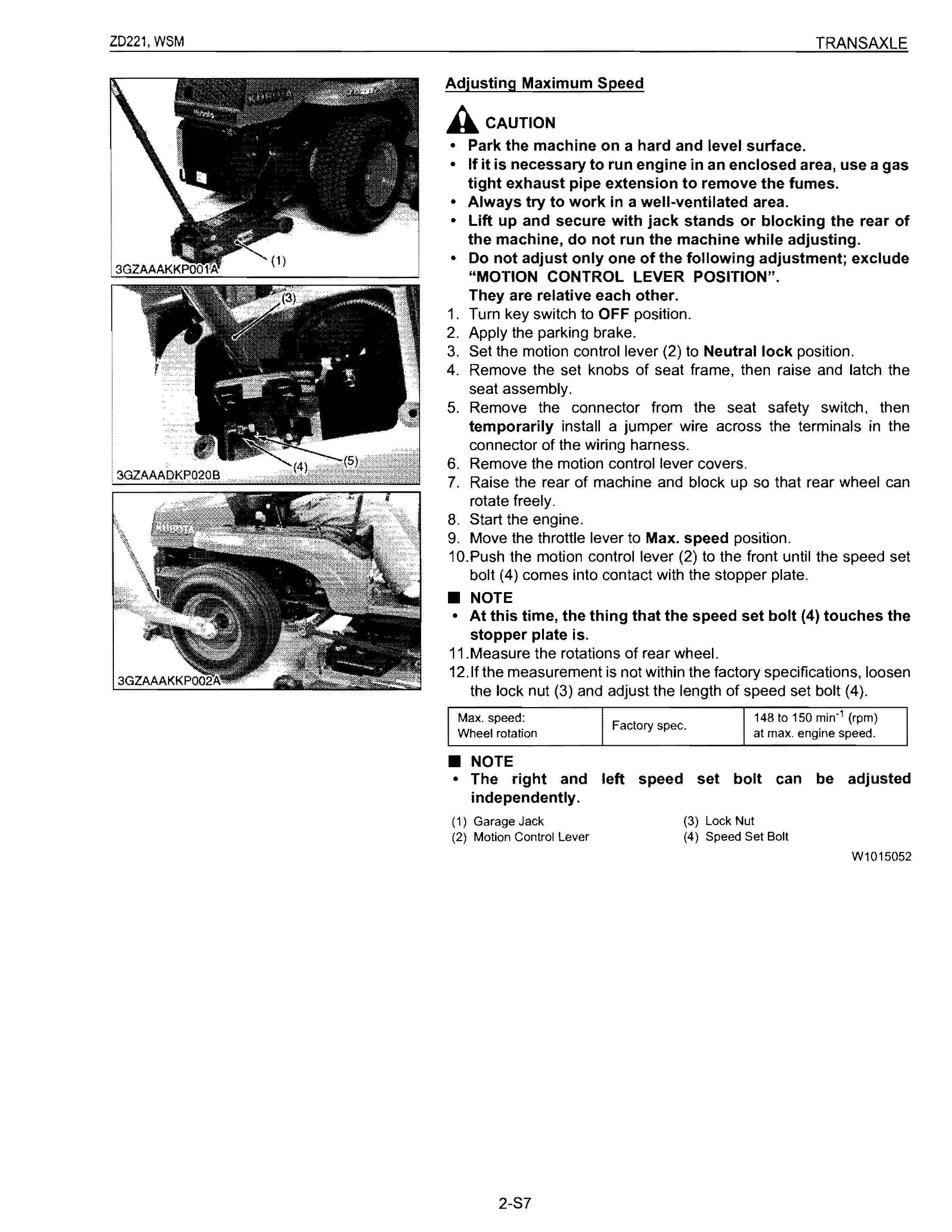
Adjusting Maximum Speed
A. CAUTION
• Park the machine on a hard and level surface.
• If it is necessary to run engine in an enclosed area, use a gas tight exhaust pipe extension to remove the fumes.
• Always try to work in a well-ventilated area.
• Lift up and secure with jack stands or blocking the rear of the machine, do not run the machine while adjusting.
• Do not adjust only one of the following adjustment; exclude "MOTION CONTROL LEVER POSITION". They are relative each other.
1. Turn key switch to OFF position.
2. Apply the parking brake.
3. Set the motion control lever (2) to Neutral lock position.
4. Remove the set knobs of seat frame, then raise and latch the seat assembly.
5. Remove the connector from the seat safety switch, then temporarily install a jumper wire across the terminals in the connector of the wiring harness.
6. Remove the motion control lever covers.
7. Raise the rear of machine and block up so that rear wheel can rotate freely.
8. Start the engine.
9. Move the throttle lever to Max. speed position.
10.Push the motion control lever (2) to the front until the speed set bolt (4) comes into contact with the stopper plate
• NOTE
• At this time, the thing that the speed set bolt (4) touches the stopper plate is.
11.Measure the rotations of rear wheel.
12.lf the measurement is not within the factory specifications, loosen the lock nut (3) and adjust the length of speed set bolt (4).
Max. speed: 148 to 150 min'1 (rpm) Factory spec. Wheel rotation at max. engine speed.
• NOTE
• The right and left speed set bolt can be adjusted independently.
(1) Garage Jack
(3) Lock Nut
(2) Motion Control lever (4) Speed Set Bolt
W1015052
3GZAAADKP022A
Checking Motion Control Lever Alignment
Acaution
• When checking, park the tractor on flat ground, apply the parking brake.
1. Check the gap A and space Bbetween the motion control levers, at the maximum forward position. If positions of the motion control levers are unequal, an adjustment is necessary.
[When adjusting alignment]
1. Stop the engine and apply the parking brake.
2. Loosen the nut and remove the boot.
• Lever position (High or Low)
3. Remove the screw (2) and select the motion control lever position, high or low.
4. Tighten the screw (2) and install the boot.
• Lever alignment (Right and Left)
5. Loosen the screws (2).
6. Slide both motion control levers forward or rearward to desired position within tab slots until levers are aligned.
7. Tighten the screws (2).
Gap A Factory spec. o to 2 mm o to 0.07 in.
Space B Factory spec.
• NOTE
3GZAAADKP024A to 20 mm 0.40 to 0.78 in.
• Ifthe ends of the levers strike against each other while in the "NEUTRAL" position, move the levers outward to the "NEUTRAL LOCK" position and carefully bend them outward.
• Move them back to the "NEUTRAL" position and check for the recommended space.
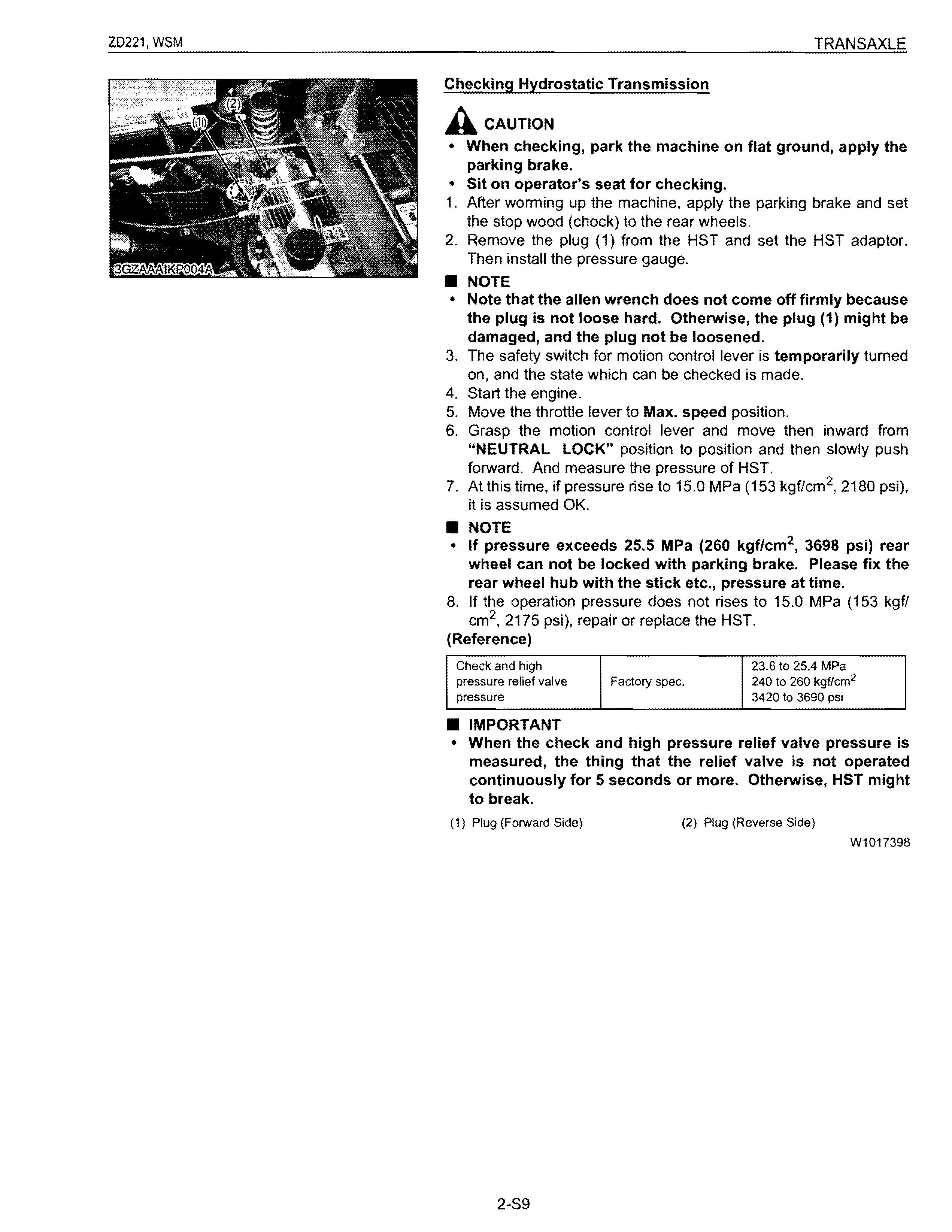
Checking Hydrostatic Transmission
A Caution
• When checking, park the machine on flat ground, apply the parking brake.
• Sit on operator's seat for checking.
1. After worming up the machine, apply the parking brake and set the stop wood (chock) to the rear wheels.
2. Remove the plug (1) from the HST and set the HST adaptor. Then install the pressure gauge.
• NOTE
• Note that the allen wrench does not come off firmly because the plug is not loose hard. Otherwise, the plug (1) might be damaged, and the plug not be loosened.
3. The safety switch for motion control lever is temporarily turned on, and the state which can be checked is made.
4. Start the engine.
5. Move the throttle lever to Max. speed position.
6. Grasp the motion control lever and move then inward from "NEUTRAL LOCK" position to position and then slowly push forward. And measure the pressure of HST.
7. At this time, if pressure rise to 15.0 MPa (153 kgf/cm 2 , 2180 psi), it is assumed OK.
• NOTE
• If pressure exceeds 25.5 MPa (260 kgflcm 2 , 3698 psi) rear wheel can not be locked with parking brake. Please fix the rear wheel hub with the stick etc., pressure at time.
8. If the operation pressure does not rises to 15.0 MPa (153 kgfl cm 2 , 2175 psi), repair or replace the HST.
(Reference)
Check and high pressure relief valve pressure Factory spec.
• IMPORTANT
23.6 to 25.4 MPa 240 to 260 kgf/cm 2 3420 to 3690 psi
• When the check and high pressure relief valve pressure is measured, the thing that the relief valve is not operated continuously for 5 seconds or more. Otherwise, HST might to break.
(1) Plug (Forward Side) (2) Plug (Reverse Side)
W1017398
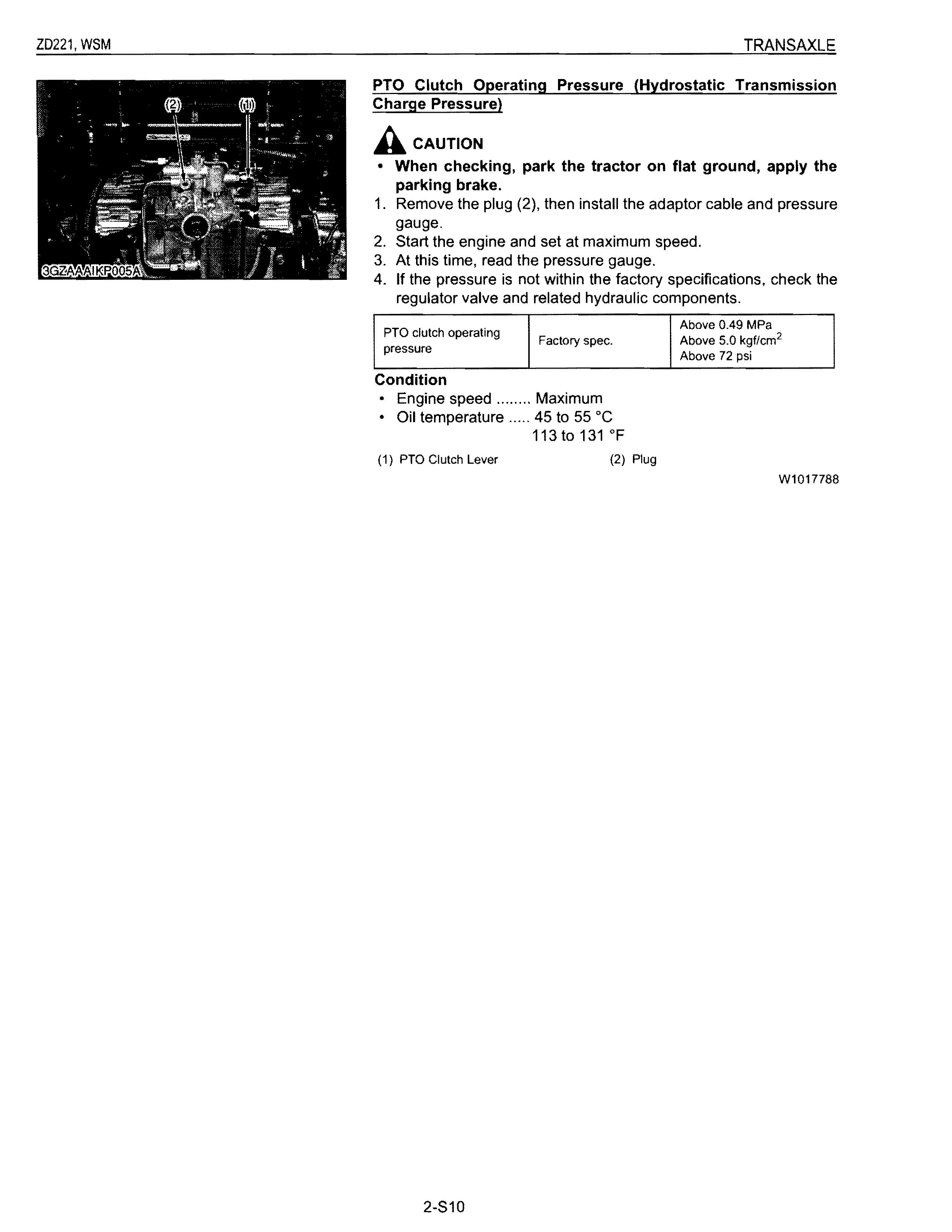
PTO Clutch Operating Pressure (Hydrostatic Transmission Charge Pressure)
Acaution
• When checking, park the tractor on flat ground, apply the parking brake.
1. Remove the plug (2), then install the adaptor cable and pressure gauge.
2. Start the engine and set at maximum speed.
3. At this time, read the pressure gauge.
4. If the pressure is not within the factory specifications, check the regulator valve and related hydraulic components.
PTO clutch operating pressure Factory spec.
Condition
• Engine speed
Maximum
• Oil temperature 45 to 55°C 113t0131OF
(1) PTO Clutch Lever (2) Plug
Above 0.49 MPa
Above 5.0 kgf/cm 2
Above 72 psi
W1017788
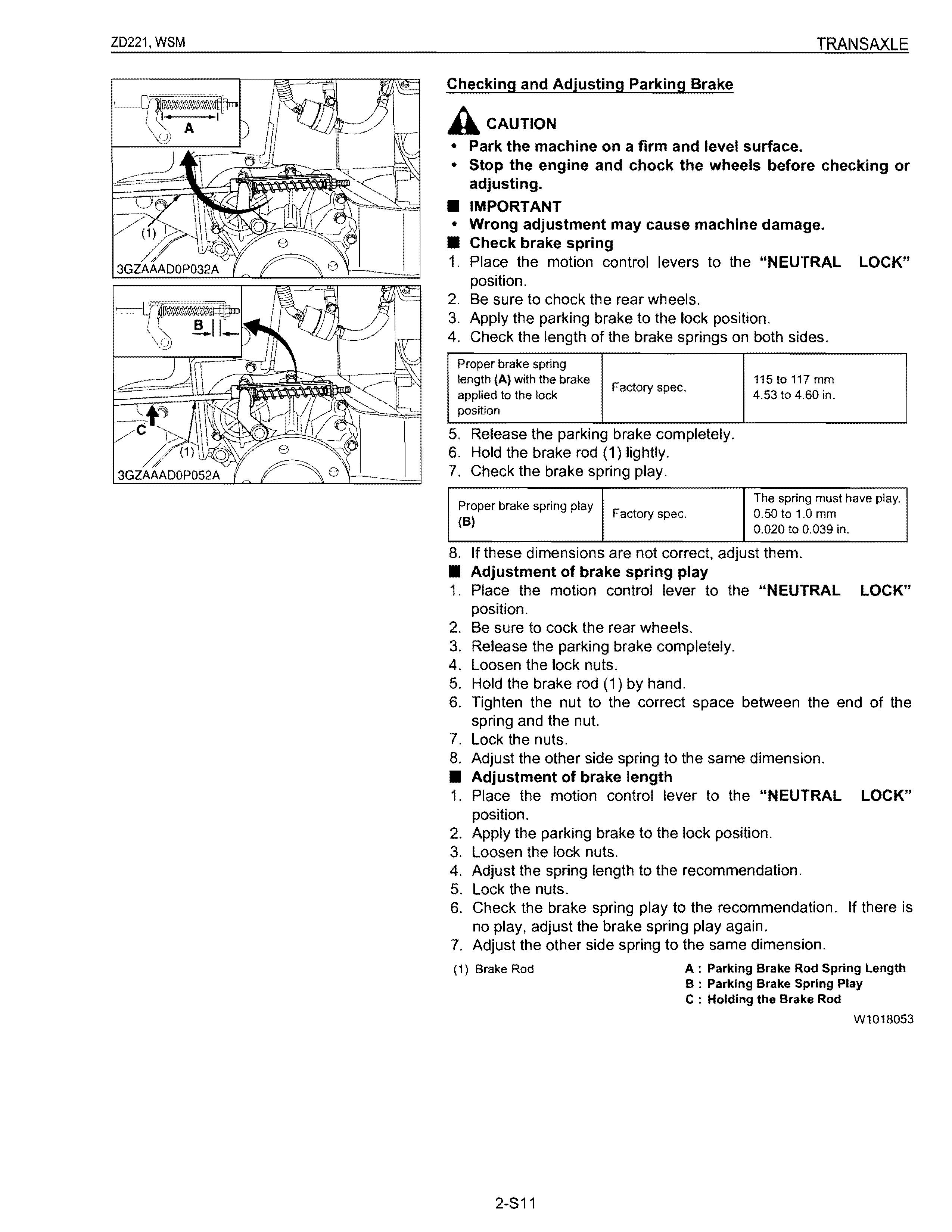
Checking and Adjusting Parking Brake
Acaution
• Park the machine on a firm and level surface.
• Stop the engine and chock the wheels before checking or adjusting.
• IMPORTANT
• Wrong adjustment may cause machine damage.
• Check brake spring
1. Place the motion control levers to the "NEUTRAL LOCK" position.
2. Be sure to chock the rear wheels.
3. Apply the parking brake to the lock position.
4. Check the length of the brake springs on both sides.
Proper brake spring length (A) with the brake applied to the lock Factory spec. 115 to 117 mm 4.53 to 4.60 in. position
5. Release the parking brake completely.
6. Hold the brake rod (1) lightly.
7. Check the brake spring play.
Proper brake spring play (B) Factory spec. The spring must have play. 0.50 to 1.0 mm 0.020 to 0.039 in.
8. If these dimensions are not correct, adjust them.
• Adjustment of brake spring play
1. Place the motion control lever to the "NEUTRAL LOCK" position.
2. Be sure to cock the rear wheels.
3. Release the parking brake completely.
4. Loosen the lock nuts.
5. Hold the brake rod (1) by hand.
6. Tighten the nut to the correct space between the end of the spring and the nut.
7. Lock the nuts.
8. Adjust the other side spring to the same dimension.
• Adjustment of brake length
1. Place the motion control lever to the "NEUTRAL LOCK" position.
2. Apply the parking brake to the lock position.
3. Loosen the lock nuts.
4. Adjust the spring length to the recommendation.
5. Lock the nuts.
6. Check the brake spring play to the recommendation. If there is no play, adjust the brake spring play again.
7. Adjust the other side spring to the same dimension.
(1) Brake Rod
A : Parking Brake Rod Spring Length
B: Parking Brake Spring Play
C : Holding the Brake Rod
W1018053
3GZAAAIOP037A
Checking Parking Brake on the Slope
1. Place the machine on a 1r ramp A.
2. Apply the parking brake.
3. Place the motion control levers in "NEUTRAL LOCK" position and shut off the engine.
4. Check that the machine does not move
• NOTE
• For parking brake test purposes, only use 17° ramp "A".
A: 17° ramp
W1018886