2 minute read
3. CHARGING SYSTEM


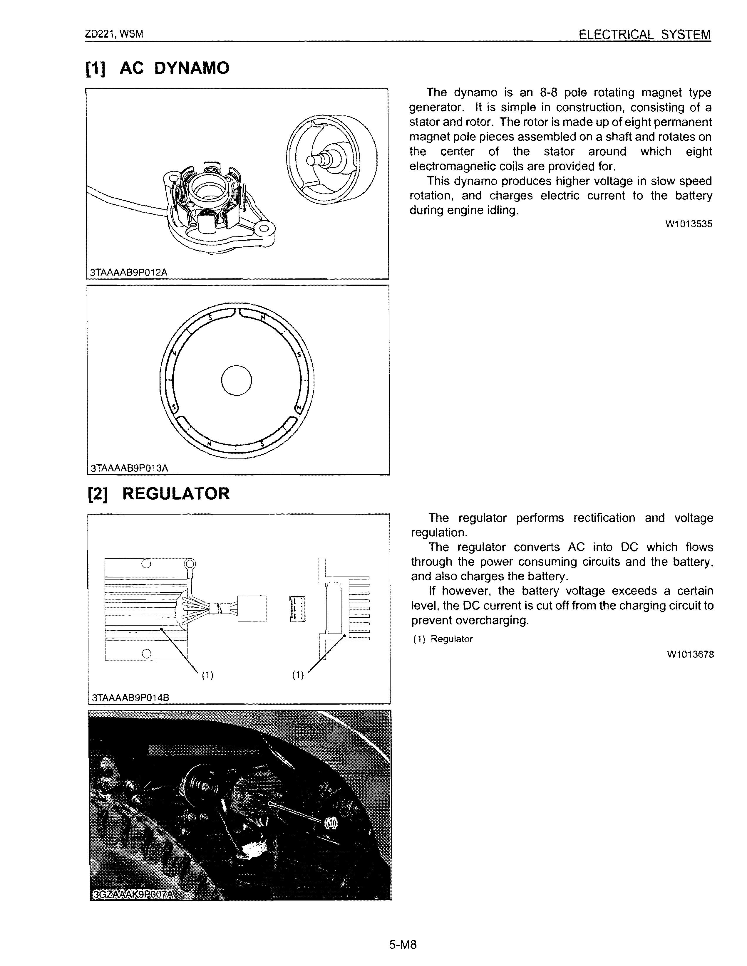
The dynamo is an 8-8 pole rotating magnet type generator. It is simple in construction, consisting of a stator and rotor. The rotor is made up of eight permanent magnet pole pieces assembled on a shaft and rotates on the center of the stator around which eight electromagnetic coils are provided for.
This dynamo produces higher voltage in slow speed rotation, and charges electric current to the battery during engine idling.
W1013535
The regulator performs rectification and voltage regulation.
The regulator converts AC into DC which flows through the power consuming circuits and the battery, and also charges the battery.
If however, the battery voltage exceeds a certain level, the DC current is cut off from the charging circuit to prevent overcharging.
W1013678
[3] EASY CHECKER
To check the conditions of tractor easily before and during operation, easy checker combination of lamps on the easy checker board is provided.
• Indication Items
(1) Oil Pressure Lamp
3GZAAAK9P008A r---(2)---(3)-------,
When the engine oil pressure is low, this lamp illuminates.
(2) Charge Lamp
When the charging system is not functioning properly, this lamp illuminates.
(3) Pre-heat Indicator Lamp
When the key switch is in the "Pre-heat" position, the pre-heat indicator lamp illuminates.
(4) Fuel Lamp
When the fuel in the RH tank goes below the prescribed level, the fuel level warning lamp illuminates.
W1013747
• Oil Pressure Switch
While oil pressure is high and the force applied to the diaphragm (2) is larger than the spring tension, the terminal contact (1) is open separated from the body contact (3). If the pressure drops below approx. 49 kPa (0.5 kgf/cm 2 , 7.1 psi), the contact closes.
(1) Terminal Contact
(2) Diaphragm
(3) Body Contact
W1013868
3TAAAAB9P020A
The fuel quantity and coolant temperature are indicated by the ammeters. The ammeters indicate each amperage flowing through the fuel level sensor for the fuel quantity detection and through the coolant temperature sensor for the coolant temperature detection.
[2] COOLANT TEMPERATURE
• Fuel Level Sensor
The remaining fuel quantity is detected by the fuel level sensor installed in the fuel tank and indicated on the fuel gauge. For detection, a float and a resistor are used. As the float lowers, the resistance of the variable resistor varies. The relation between the amount of fuel and the resistance is as follows. F 1/2 E (Remaining fuel of approx. 2.0 L. 0.53 U.S.gal.. 0.44 Imp.gal.)
1 to 5!1 28.5 to 36.5 !1 103 to 117 !1 W1013985
• Coolant Temperature Sensor (Thermo Unit)
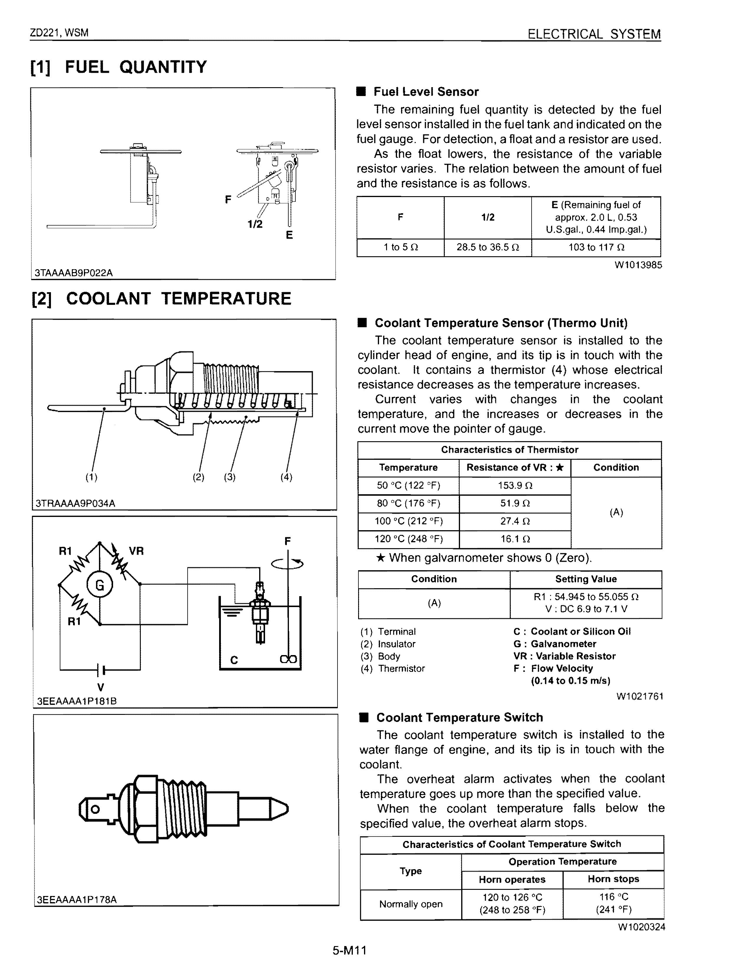
The coolant temperature sensor is installed to the cylinder head of engine, and its tip is in touch with the coolant. It contains a thermistor (4) whose electrical resistance decreases as the temperature increases.
Current varies with changes in the coolant temperature, and the increases or decreases in the current move the pOinter of gauge.
* When galvarnometer shows 0 (Zero).
• Coolant Temperature Switch
The coolant temperature switch is installed to the water flange of engine, and its tip is in touch with the coolant.
The overheat alarm activates when the coolant temperature goes up more than the specified value. When the coolant temperature falls below the specified value, the overheat alarm stops.