13 minute read
[4] SERVICING


(1) Cylinder Head and Valves
(1 )
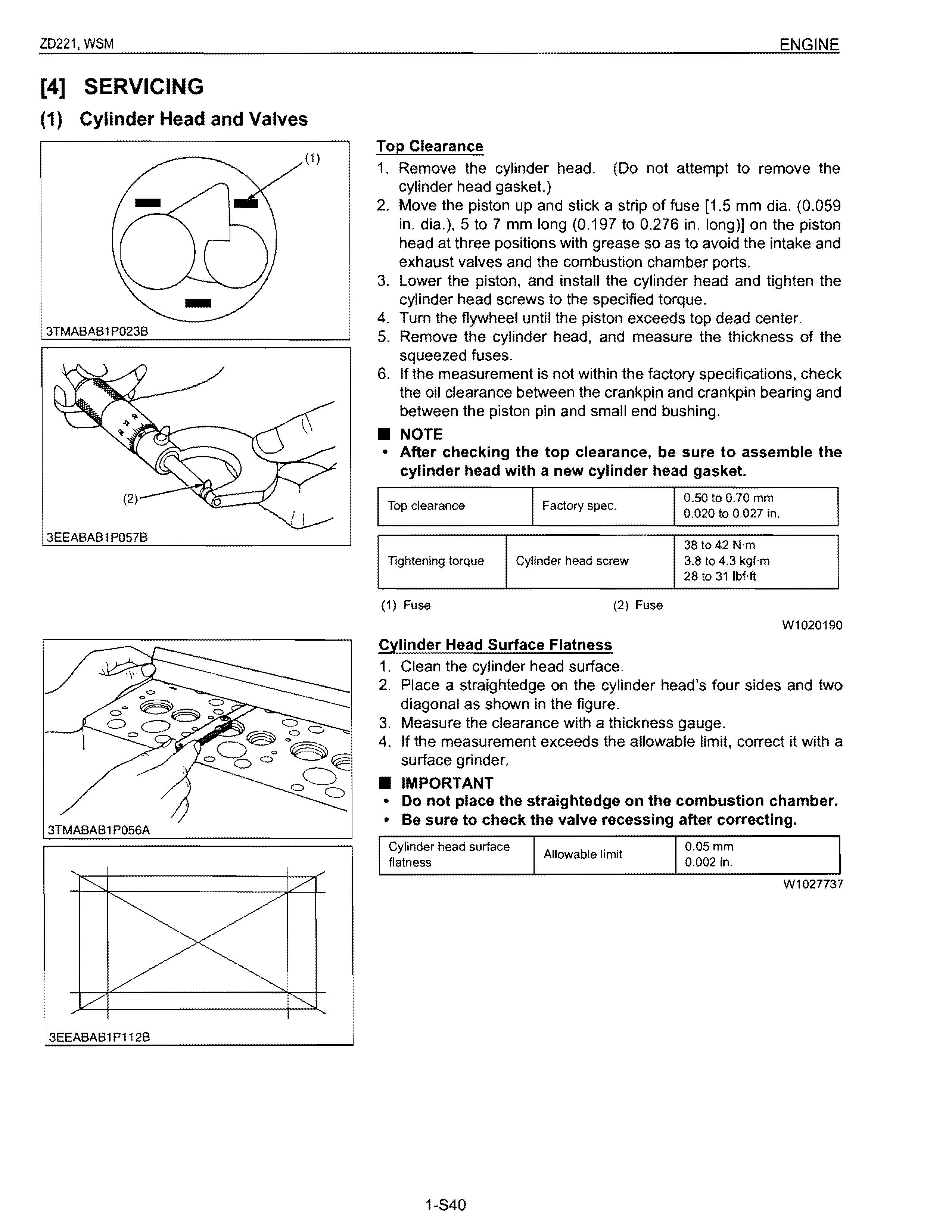
Top Clearance
1. Remove the cylinder head. (Do not attempt to remove the cylinder head gasket.)
2. Move the piston up and stick a strip of fuse [1.5 mm dia. (0.059 in. dia.), 5 to 7 mm long (0.197 to 0.276 in. long)] on the piston head at three positions with grease so as to avoid the intake and exhaust valves and the combustion chamber ports.
3. Lower the piston, and install the cylinder head and tighten the cylinder head screws to the specified torque.
4. Turn the flywheel until the piston exceeds top dead center.
3TMABABl P023B
5. Remove the cylinder head, and measure the thickness of the squeezed fuses.
6. If the measurement is not within the factory specifications, check the oil clearance between the crankpin and crankpin bearing and between the piston pin and small end bushing
• NOTE to 0.70 mm o to 0.027
• After checking the top clearance, be sure to assemble the cylinder head with a new cylinder head gasket.
3EEABAB1P057B
Cylinder Head Surface Flatness
1. Clean the cylinder head surface.
Wl020190
2. Place a straightedge on the cylinder head's four sides and two diagonal as shown in the figure.
3. Measure the clearance with a thickness gauge.
4. If the measurement exceeds the allowable limit, correct it with a surface grinder.
• IMPORTANT
• Do not place the straightedge on the combustion chamber.
• Be sure to check the valve recessing after correcting.
Cylinder Head Flaw
1. Prepare an air spray red check.
2. Clean the surface of the cylinder head with detergent (2).
3. Spray the cylinder head surface with the red permeative liquid (1). Leave it five to ten minutes after spraying.
4. Wash away the read permeative liquid on the cylinder head surface with the detergent (2).
5. Spray the cylinder head surface with white developer (3).
6. If flawed, it can be identified as red marks.
(1) Red Permeative Liquid (3) White Developer
(2) Detergent
Valve Recessing
W1076542
1. Clean the cylinder head surface, valve face and valve seat.
2. Insert the valve into the valve guide.
3. Measure the valve recessing with a depth gauge.
4. If the measurement exceeds the allowable limit. replace the valve.
5. If it still exceeds the allowable limit after replacing the valve, replace the cylinder head.
(1) Cylinder Head Surface (A) Recessing (8)
Clearance between Valve Stem and Valve Guide
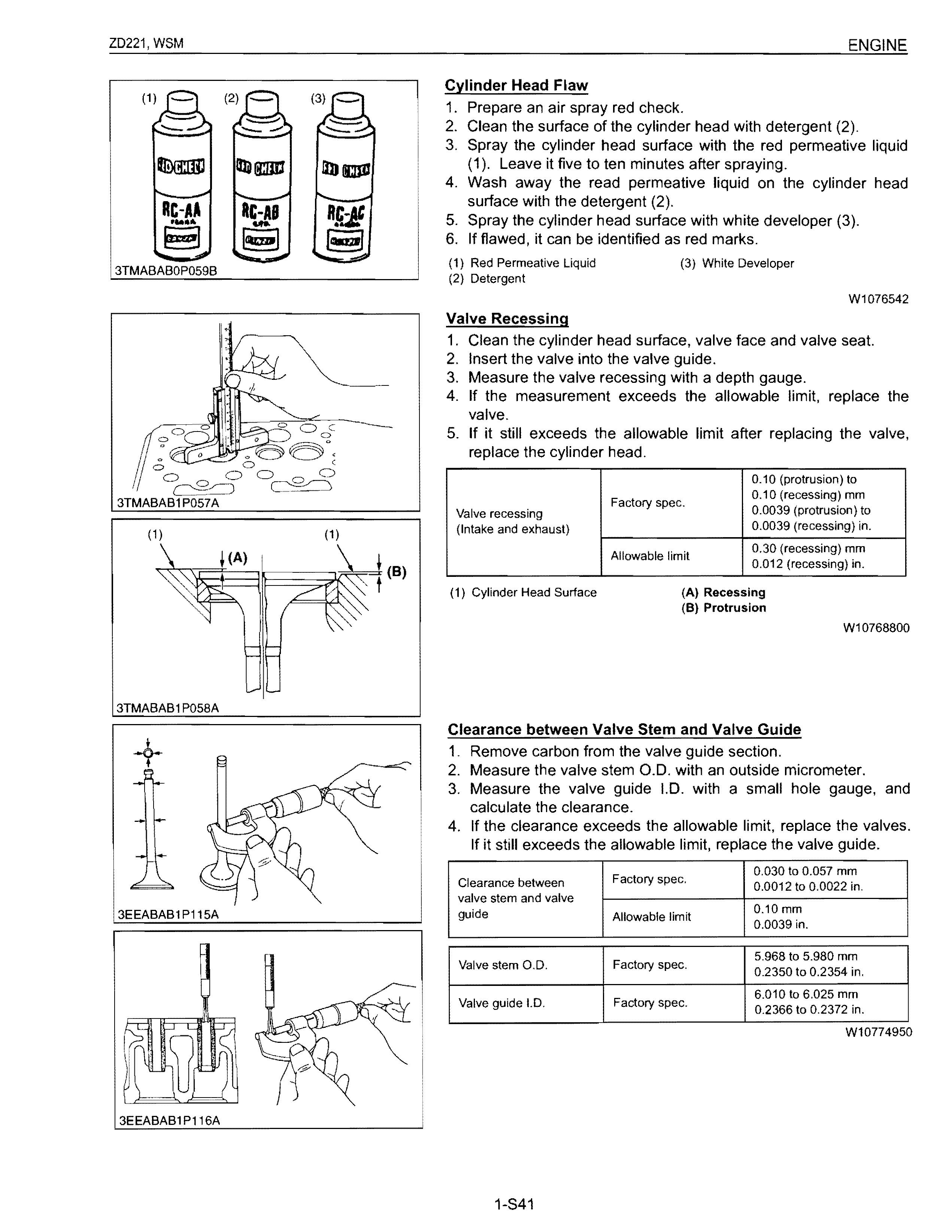
1. Remove carbon from the valve guide section.
2. Measure the valve stem 0.0. with an outside micrometer.
3. Measure the valve guide 1.0. with a small hole gauge, and calculate the clearance.
4. If the clearance exceeds the allowable limit, replace the valves. If it still exceeds the allowable limit, replace the valve guide.
3TMABABl
(A) (8)
Replacing Valve Guide
(When removing)
1. Press out the used valve guide using a valve guide replacing tool. (See page "SPECIAL TOOLS".)
(When installing)
1. Clean a new valve guide and valve guide bore, and apply engine oil to them.
2. Press in a new valve guide using a valve guide replacing tool.
3. Ream precisely the I.D. of the valve guide to the specified dimension.
Valve guide 1.0. 6.010 to 6.025 mm Factory spec.
(Intake and exhaust) 0.2366 to 0.2372 in.
• IMPORTANT
• Do not hit the valve guide with a hammer during replacement.
(A) When Removing (B) When Installing
Valve Seating
W10278890
1. Coat the valve face lightly with prussian blue and put the valve on its seat to check the contact.
2. If the valve does not seat all the way around the valve seat or the valve contact is less than 70 %, correct the valve seating as follows.
3. If the valve contact does not comply with the reference value, replace the valve or correct the contact of valve seating.
2,12 mm
Valve seat width Factory spec. 0.0835 in.
(1) Correct (3) Incorrect
(2) Incorrect
W10282190
3TMABAB1
Correcting Valve and Valve Seat
• NOTE
• Before correcting the valve and seat, check the valve stem and the 1.0. of valve guide section, and repair them if necessary.
• After correcting the valve seat. be sure to check the valve recessing.
1) Correcting Valve
1. Correct the valve with a valve refacer.
2) Correcting Valve Seat
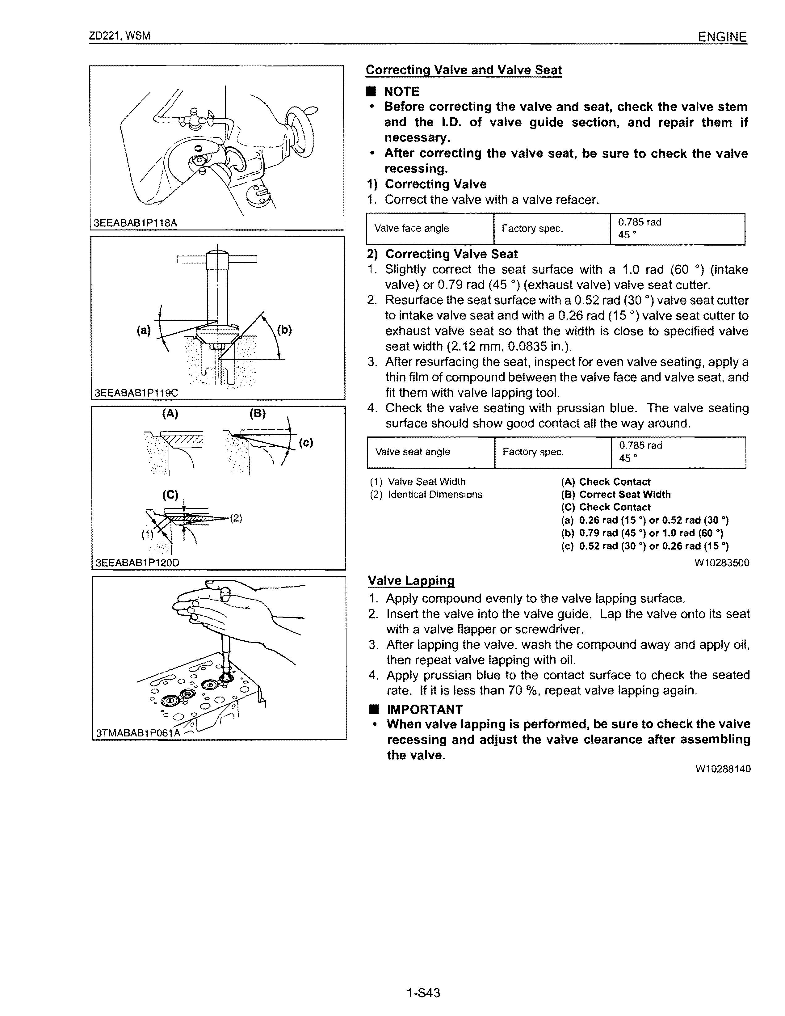
1. Slightly correct the seat surface with a 1.0 rad (60 0) (intake valve) or 0.79 rad (45 0) (exhaust valve) valve seat cutter.
2. Resurface the seat surface with a 0.52 rad (30 0) valve seat cutter to intake valve seat and with a 0.26 rad (15 0) valve seat cutter to exhaust valve seat so that the width is close to specified valve seat width (2.12 mm, 0.0835 in.).
3. After resurfacing the seat, inspect for even valve seating, apply a thin film of compound between the valve face and valve seat, and fit them with valve lapping tool.
4. Check the valve seating with prussian blue. The valve seating surface should show good contact all the way around.
0.785 rad
Valve seat angle Factory spec. 45·
(1) Valve Seat Width
Identical Dimensions
Valve Lapping
1. Apply compound evenly to the valve lapping surface.
2. Insert the valve into the valve guide. Lap the valve onto its seat with a valve flapper or screwdriver.
3. After lapping the valve, wash the compound away and apply oil, then repeat valve lapping with oil.
4. Apply prussian blue to the contact surface to check the seated rate. If it is less than 70 %, repeat valve lapping again
• IMPORTANT
• When valve lapping is performed, be sure to check the valve recessing and adjust the valve clearance after assembling the valve.
W10288140
3EEABAB1 P121 C
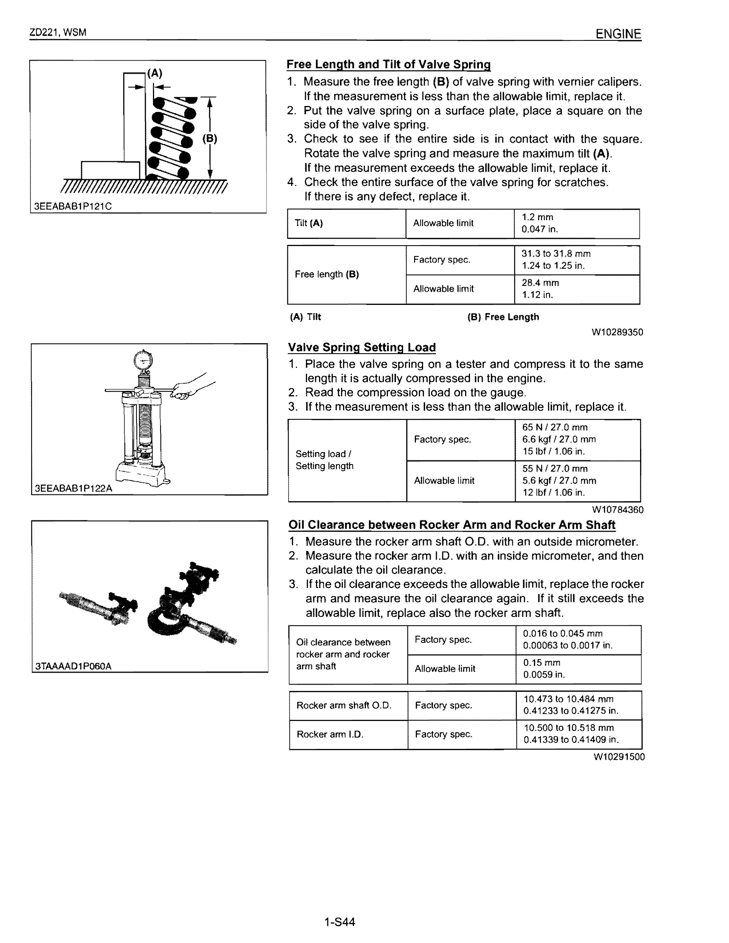
Free Length and Tilt of Valve Spring
1. Measure the free length (8) of valve spring with vernier calipers. If the measurement is less than the allowable limit, replace it.
2. Put the valve spring on a surface plate, place a square on the side of the valve spring.
3. Check to see if the entire side is in contact with the square. Rotate the valve spring and measure the maximum tilt (A). If the measurement exceeds the allowable limit, replace it.
4. Check the entire surface of the valve spring for scratches. If there is any defect, replace it.
(A) Tilt (B) Free Length
Valve Spring Setting Load
W10289350
1. Place the valve spring on a tester and compress it to the same length it is actually compressed in the engine.
2. Read the compression load on the gauge.
3. If the measurement is less than the allowable limit, replace it.
NI 27,0 mm spec. 6.6 kgf 127.0 mm
3EEABAB1P122A
W10784360
Oil Clearance between Rocker Arm and Rocker Arm Shaft
1. Measure the rocker arm shaft 0.0. with an outside micrometer.
2. Measure the rocker arm 1.0. with an inside micrometer, and then calculate the oil clearance.
3. If the oil clearance exceeds the allowable limit, replace the rocker arm and measure the oil clearance again. If it still exceeds the allowable limit, replace also the rocker arm shaft. Oil
3TAAAAD1 P060A
Push Rod Alignment
1. Place the push rod on V blocks.
2. Measure the push rod alignment.
3. If the measurement exceeds the allowable limit, replace the push rod.
3TMABAB 1P062A
Oil Clearance between Tappet and Tappet Guide Bore
1. Measure the tappet 0.0. with an outside micrometer.
2. Measure the 1.0. of the tappet guide bore with a cylinder gauge, and calculate the oil clearance.
3. If the oil clearance exceeds the allowable limit or the tappet is damaged, replace the tappet.
3EEABAB1 P124A
(2) Timing Gears, Camshaft and Governor Gear
Timing Gear Backlash
1. Set a dial indicator (lever type) with its tip on the gear tooth.
2. Move the gear to measure the backlash, holding its mating gear.
3. If the backlash exceeds the allowable limit, check the oil clearance of the shafts and the gear.
4. If the oil clearance is proper, replace the gear.
Idle Gear and Idle Gear 1 Side Clearance
1. Set a dial indicator with its tip on the idle gear.
2. Measure the side clearance by moving the idle gear to the front and rear.
3. If the measurement exceeds the allowable limit, replace the idle gear collar.
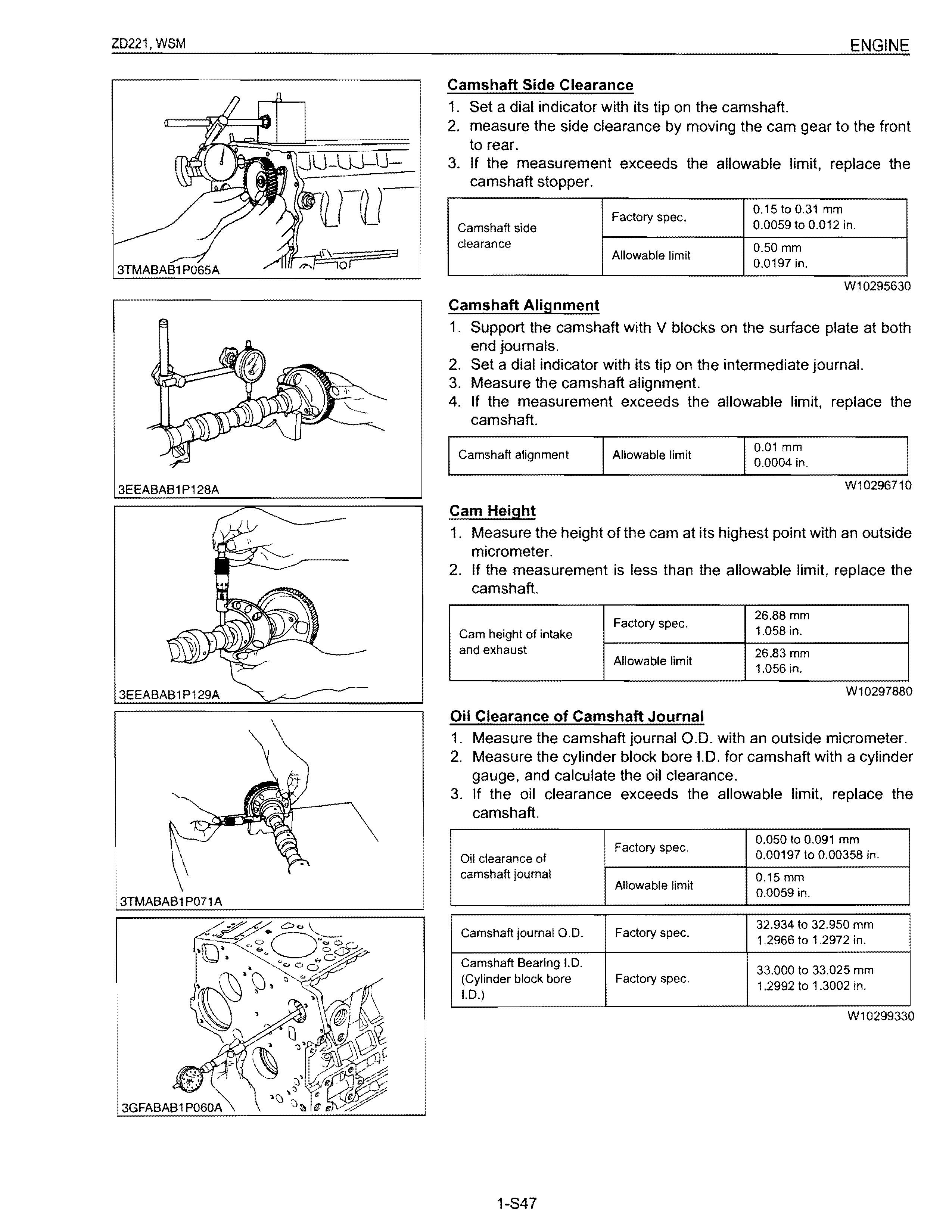
Camshaft Side Clearance
1. Set a dial indicator with its tip on the camshaft.
2. measure the side clearance by moving the cam gear to the front to rear.
3. If the measurement exceeds the allowable limit, replace the camshaft stopper.
Camshaft Alignment
1. Support the camshaft with V blocks on the surface plate at both end journals.
2. Set a dial indicator with its tip on the intermediate journal.
3. Measure the camshaft alignment.
4. If the measurement exceeds the allowable limit, replace the camshaft.
1. Measure the height of the cam at its highest point with an outside micrometer.
2. If the measurement is less than the allowable limit, replace the camshaft.
Oil Clearance of Camshaft Journal
1. Measure the camshaft journal 0.0. with an outside micrometer.
2. Measure the cylinder block bore 1.0. for camshaft with a cylinder gauge, and calculate the oil clearance.
3. If the oil clearance exceeds the allowable limit, replace the camshaft.
3TMABAB1 P069A
Oil Clearance between Idle Gear, Idle Gear 1, Idle Gear Shaft and Idle Gear Bushing
1. Measure the idle gear shaft 0.0. with an outside micrometer.
2. Measure the idle gear bushing 1.0. with an inside micrometer, and calculate the oil clearance.
3. If the oil clearance exceeds the allowable limit, replace the bushing.
If it still exceeds the allowable limit, replace the idle gear shaft.
Oil clearance between Factory spec. idle gear shaft and idle gear bushing
Replacing Idle Gear Bushing
(When removing)
1. Press out the used idle gear bushing using an idle gear bushing replacing tool. (See page "SPECIAL TOOLS".) (When installing)
1. Clean a new idle gear bushing and idle gear bore, and apply engine oil to them.
2. Press in a new bushing using an idle gear bushing replacing tool, until it is flush with the end of the idle gear.
(A) When Removing (B) When Installing
(3) Piston and Connecting Rod
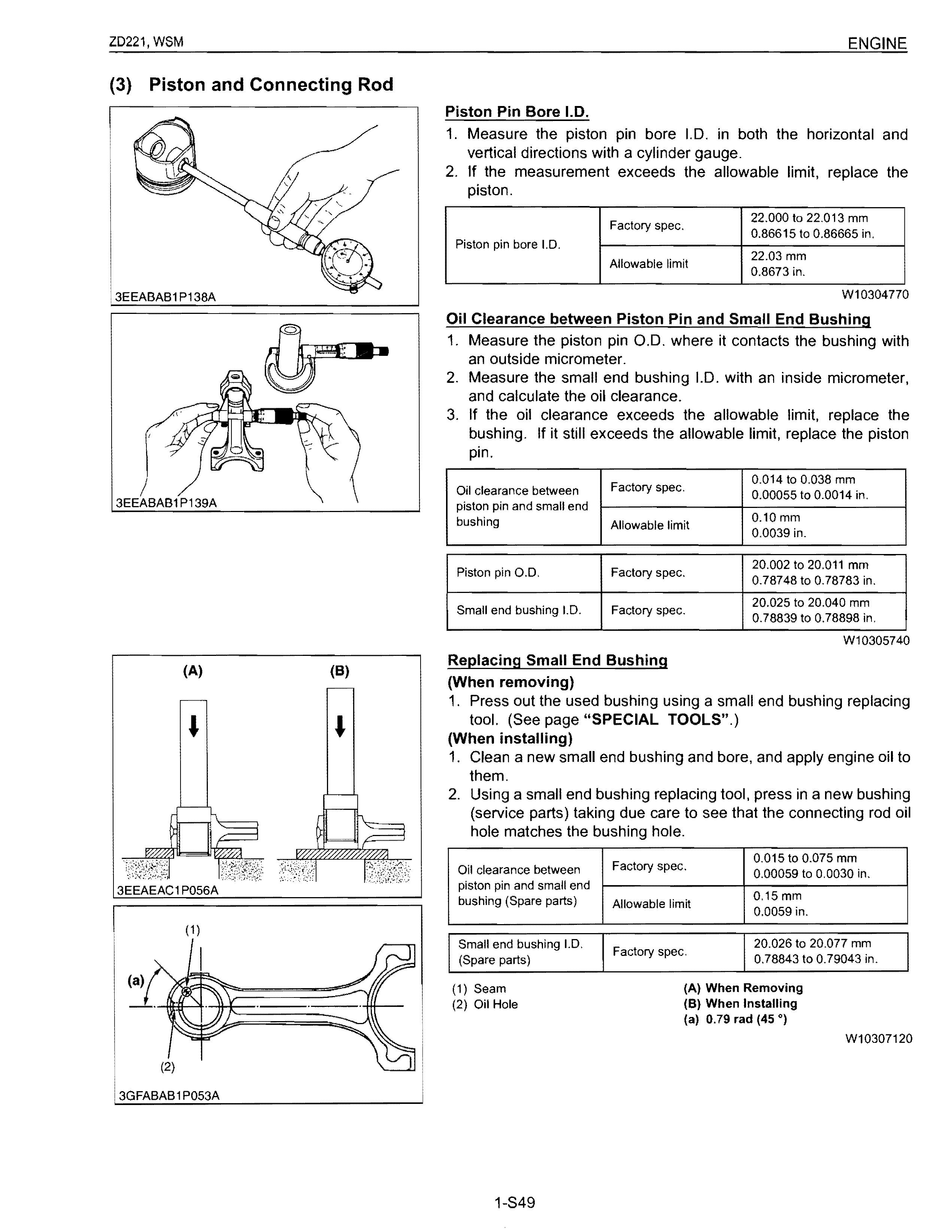
Piston Pin Bore 1.0.
1. Measure the piston pin bore 1.0. in both the horizontal and vertical directions with a cylinder gauge.
2. If the measurement exceeds the allowable limit, replace the piston. Piston
Oil Clearance between Piston Pin and Small End Bushing
1. Measure the piston pin 0.0. where it contacts the bushing with an outside micrometer.
2. Measure the small end bushing 1.0. with an inside micrometer, and calculate the oil clearance.
3. If the oil clearance exceeds the allowable limit, replace the bushing. If it still exceeds the allowable limit, replace the piston pin.
1. Press out the used bushing using a small end bushing replacing tool. (See page "SPECIAL TOOLS".)
(When installing) piston pin and small end
1. Clean a new small end bushing and bore, and apply engine oil to them.
2. Using a small end bushing replacing tool, press in a new bushing (service parts) taking due care to see that the connecting rod oil hole matches the bushing hole.
3TMABABOP056A
Connecting Rod Alignment
• NOTE
• Since the 1.0. of the connecting rod small end bushing is the basis of this check, check bushing for wear beforehand.
1. Install the piston pin into the connecting rod.
2. Install the connecting rod on the connecting rod alignment tool.
3. Put a gauge over the piston pin, and move it against the face plate.
4. If the gauge does not fit squarely against the face plate, measure the space between the pin of the gauge and the face plate.
5. If the measurement exceeds the allowable limit, replace the connecting rod.
Connecting rod 0.05 mm Allowable limit alignment 0.002 in.
Piston Ring Gap
W10314620
1. Insert the piston ring into the lower part of the cylinder (the least worn out part) with a piston.
2. Measure the ring gap with a thickness gauge.
3. If the measurement exceeds the allowable limit, replace the piston ring.
3EEABAB1 P144A
W10310120
3EEABAB1 P142A (8)
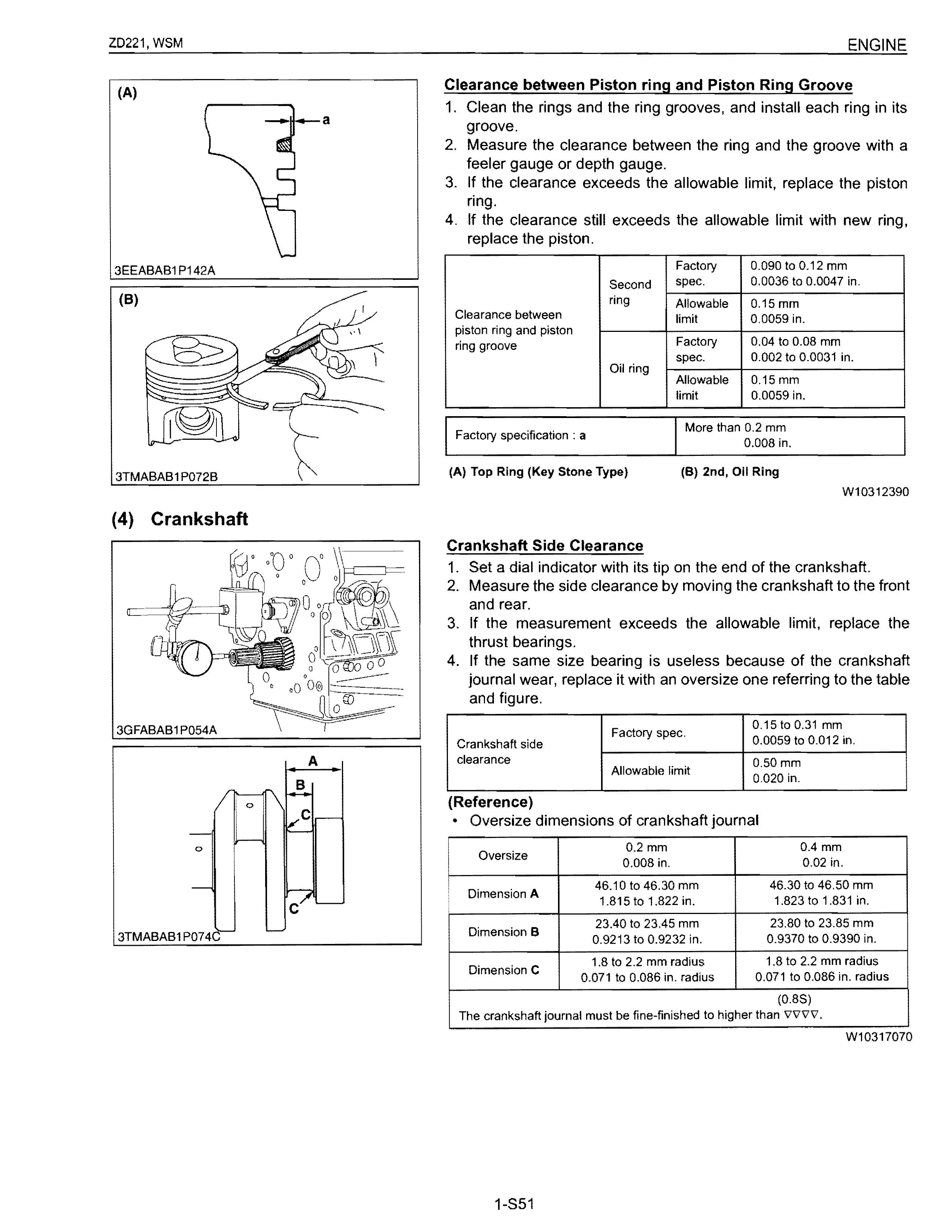
Clearance between Piston ring and Piston Ring Groove
1. Clean the rings and the ring grooves, and install each ring in its groove.
2. Measure the clearance between the ring and the groove with a feeler gauge or depth gauge.
3. If the clearance exceeds the allowable limit, replace the piston ring.
4. If the clearance still exceeds the allowable limit with new ring, replace the piston.
Clearance between in. piston ring and piston ring groove
3TMABAB 1P072B
(4)
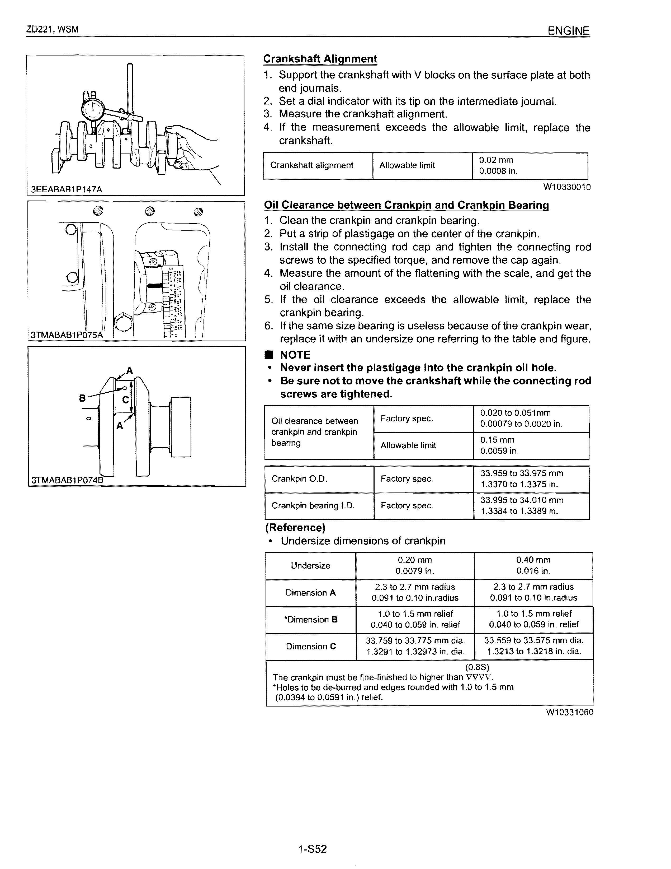
Crankshaft Side Clearance
1. Set a dial indicator with its tip on the end of the crankshaft.
2. Measure the side clearance by moving the crankshaft to the front and rear.
3. If the measurement exceeds the allowable limit. replace the thrust bearings.
4. If the same size bearing is useless because of the crankshaft journal wear, replace it with an oversize one referring to the table and figure.
3GFABAB1 P054A
(Reference)
3TMABAB1 P074
The crankshaft journal must be fine-finished to higher than vvvv.
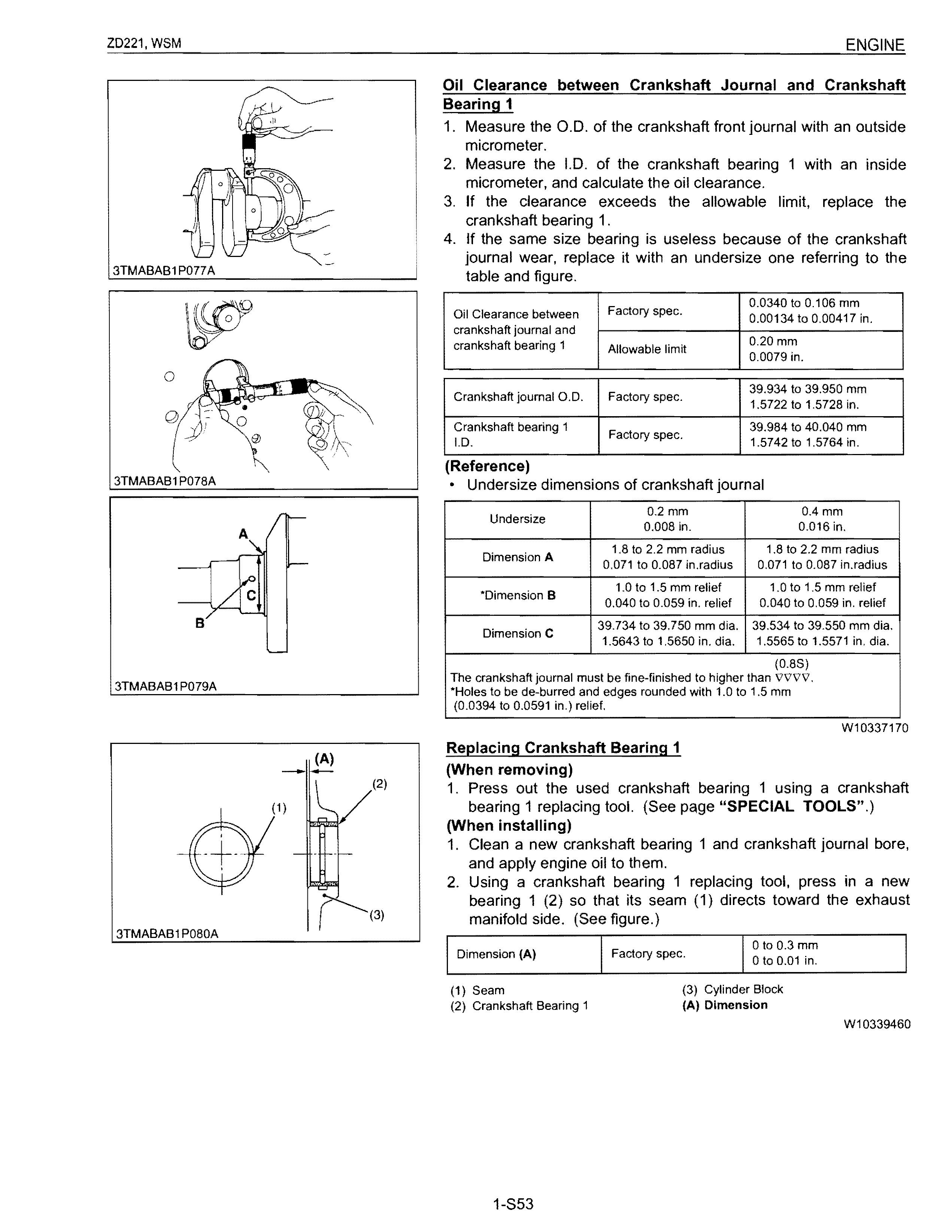
Crankshaft Alignment
1. Support the crankshaft with V blocks on the surface plate at both end joumals.
2. Set a dial indicator with its tip on the intermediate joumal.
3. Measure the crankshaft alignment.
4. If the measurement exceeds the allowable limit, replace the crankshaft.
Oil Clearance between Crankpin and Crankpin Bearing
1. Clean the crankpin and crankpin bearing.
2. Put a strip of plastigage on the center of the crankpin.
3. Install the connecting rod cap and tighten the connecting rod screws to the specified torque, and remove the cap again.
4. Measure the amount of the flattening with the scale, and get the oil clearance.
5. If the oil clearance exceeds the allowable limit, replace the crankpin bearing.
6. If the same size bearing is useless because of the crankpin wear, replace it with an undersize one referring to the table and figure .
• NOTE
• Never insert the plastigage into the crankpin oil hole.
• Be sure not to move the crankshaft while the connecting rod screws are tightened.
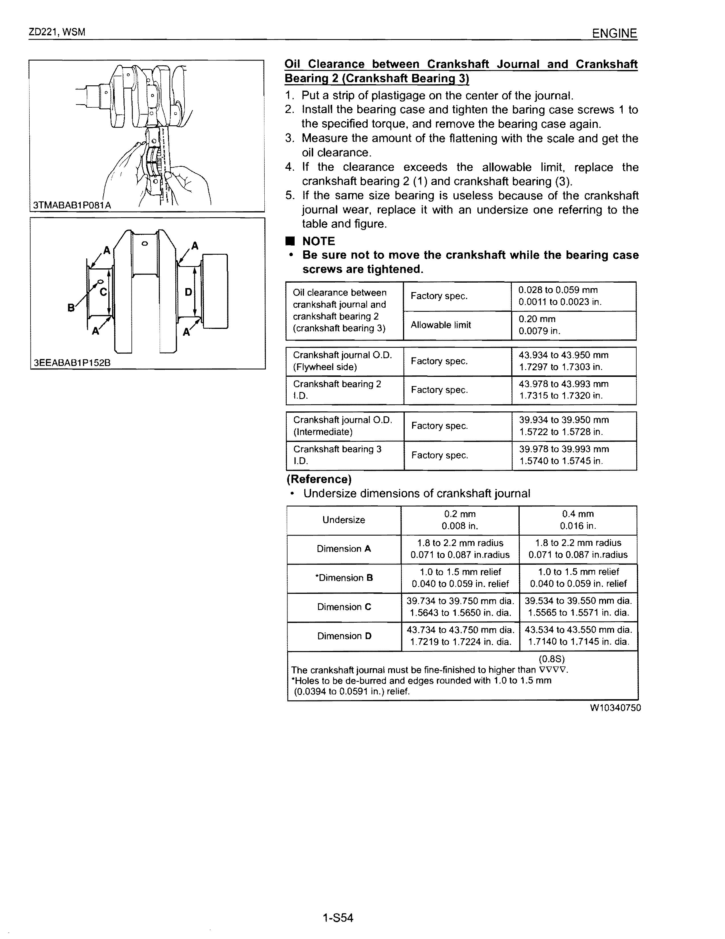
Oil Clearance between Crankshaft Journal and Crankshaft Bearing 1
1. Measure the 0.0. of the crankshaft front journal with an outside micrometer.
2. Measure the I.D. of the crankshaft bearing 1 with an inside micrometer, and calculate the oil clearance.
3. If the clearance exceeds the allowable limit, replace the crankshaft bearing 1.
4. If the same size bearing is useless because of the crankshaft journal wear, replace it with an undersize one referring to the table and figure.
(Reference)
The crankshaft journal must be fine-finished to higher than to be de-burred and edges rounded with to 0.0591 in.) relief.
Replacing Crankshaft Bearing 1
(When removing) to 1.5 mm
1. Press out the used crankshaft bearing 1 using a crankshaft bearing 1 replacing tool. (See page "SPECIAL TOOLS".)
(When installing)
1. Clean a new crankshaft bearing 1 and crankshaft journal bore, and apply engine oil to them.
2. Using a crankshaft bearing 1 replacing tool, press in a new bearing 1 (2) so that its seam (1) directs toward the exhaust manifold side. (See figure.)
Oil Clearance between Crankshaft Journal and Crankshaft Bearing 2 (Crankshaft Bearing 3)
1. Put a strip of plastigage on the center of the journal.
2. Install the bearing case and tighten the baring case screws 1 to the specified torque, and remove the bearing case again.
3. Measure the amount of the flattening with the scale and get the oil clearance.
4. If the clearance exceeds the allowable limit, replace the crankshaft bearing 2 (1) and crankshaft bearing (3).
5. If the same size bearing is useless because of the crankshaft journal wear, replace it with an undersize one referring to the table and figure
• NOTE
• Be sure not to move the crankshaft while the bearing case screws are tightened.
Oil clearance between crankshaft journal and crankshaft bearing 2 bearing 3) Crankshaft
(Reference)
3EEACAB1P019A
Replacing Crankshaft Sleeve
1. Remove the used crankshaft sleeve.
2. Set the sleeve guide (2) to the crankshaft.
3. Heat a new sleeve to a temperature between 150 and 200°C (302 and 392 OF), and fix the sleeve to the crankshaft as shown in figure.
4. Press fit the sleeve using the auxiliary socket for pushing (3)
• NOTE
• Mount the sleeve with its largely chamfered surface facing outward.
• Should heating is not enough, a sleeve might stop halfway, so careful.
(1) Crankshaft Sleeve (3) Auxiliary Socket for Pushing
(2) Sleeve Guide (4) Crankshaft
W1045923
3EEACAB1P020B
(5) Cylinder
Cylinder Wear
1. Measure the 1.0. of the cylinder at the six positions (see figure) with a cylinder gauge to find the maximum and minimum I.D.'s.
2. Get the difference (Maximum wear) between the maximum and the minimum 1.0.'s.
3. If the wear exceeds the allowable limit, bore and hone to the oversize dimension. (Refer to "Correcting Cylinder".)
4. Visually check the cylinder wall for scratches. If deep scratches are found, the cylinder should be bored. (Refer to "Correcting Cylinder". )
(A) Top (a) Right-angled to Piston Pin
(B) Middle (b) Piston Pin Direction
(C) Bottom (Skirt)
Correcting Cylinder (Oversize)
1. When the cylinder is worn beyond the allowable limit, bore and hone it to the specified dimension.
Finishing
Hone to 2.2 to 3.0 ).ImRz (0.000087 to 0.00012 in.).IRz) vvv.
2. Replace the piston and piston rings with oversize ones. Oversize: 0.25 mm (O,0098 in.)
• NOTE
• When the oversize cylinder is worn beyond the allowable limit, replace the cylinder block with a new one.
(1) Cylinder LD. (Before Correction) (2) Cylinder LD. (Oversize)
(6) Oil Pump
Rotor Lobe Clearance
1. Measure the clearance between lobes of the inner rotor and the outer rotor with a thickness gauge.
2. If the clearance exceeds the factory specifications, replace the oil pump rotor assembly.
0.030 to 0.14 mm Rotor lobe clearance Factory spec. 0.0012 to 0.0055 in.
W10378950
Clearance between Outer Rotor and Pump Body
1. Measure the clearance between the outer rotor and the pump body with a thickness gauge.
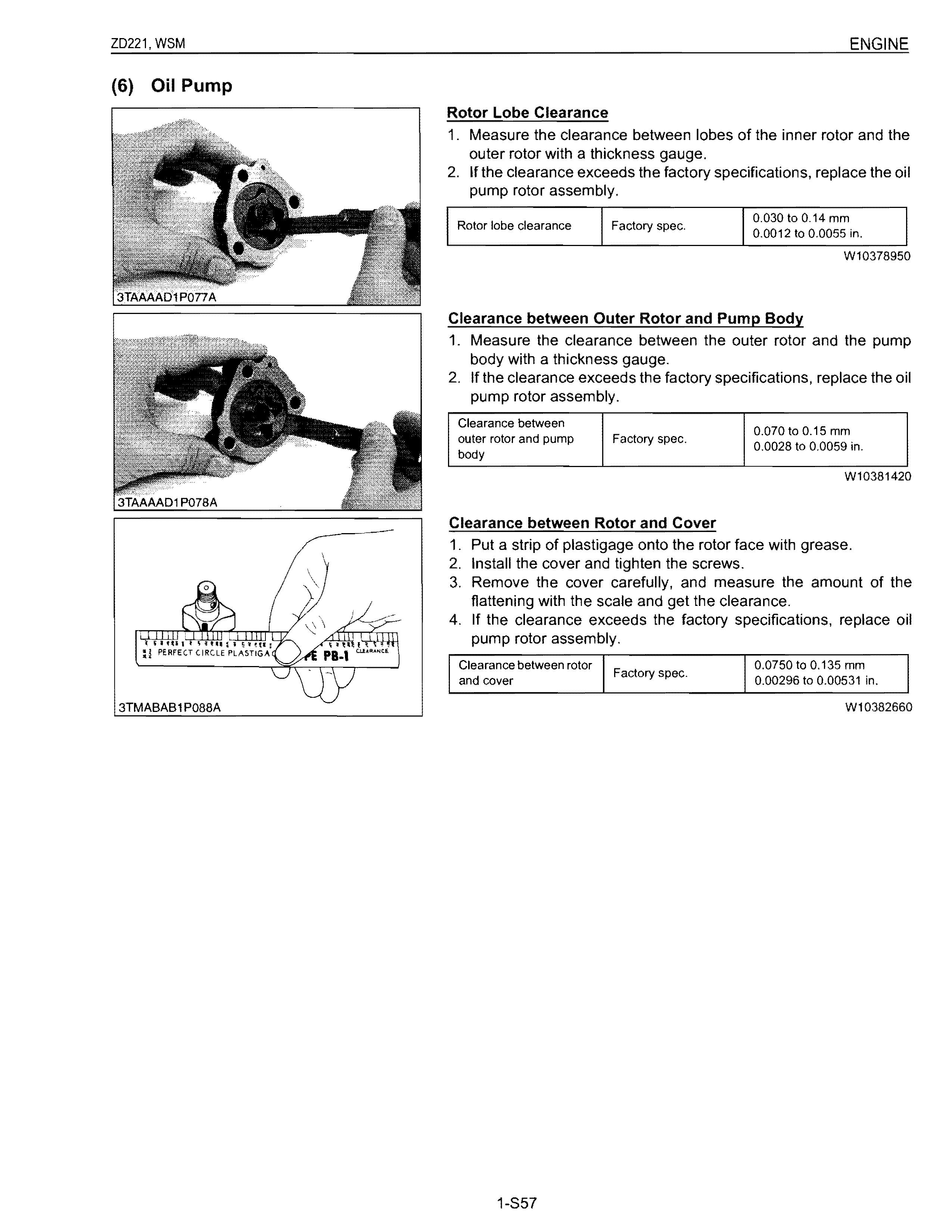
2. If the clearance exceeds the factory specifications, replace the oil pump rotor assembly.
Clearance between outer rotor and pump body Factory spec. 0.070 to 0.15 mm 0.0028 to 0.0059 in.
W10381420
Clearance between Rotor and Cover
1. Put a strip of plastigage onto the rotor face with grease.
2. Install the cover and tighten the screws.
3. Remove the cover carefully, and measure the amount of the flattening with the scale and get the clearance.
4. If the clearance exceeds the factory specifications, replace oil pump rotor assembly.
Clearance between rotor 0.0750 to 0.135 mm Factory spec. and cover 0.00296 to 0.00531 in.
W10382660