7 minute read
2. TRAVELLING SYSTEM [1] HYDROSTATIC TRANSMISSION

![[4] SERVICING](https://assets.isu.pub/document-structure/230324105859-76e47f13a5ec6f7125364bf56105590b/v1/8c394a09040bee0c5fcceca8e8030873.jpeg)
(1) Structure
(2) Pump and Motor
3GZAAADKP003A
(1) Swash plate (4) Oil (6) Piston A: Pump
(2) Piston (5) Cylinder (7) Swashplate B: Motor
(3) Cylinder
Pump and motor cylinder, each containing pistons, are connected by lines, Cylinders and lines are filled with oil. Pistons ride against swash plates located in pump and motor.
In the pump, as the cylinder rotates, pistons move across the sloping face of swash plate and slide in or out of their cylinder bores. The oil, forced out by the pump pistons, cause the motor pistons to slide out of their cylinder bores. In the motor, Sliding out of the cylinder and moving across the sloping face of swashplate, the pistons rotate the cylinder.
• Torque rise
Diameter of pump cylinder block is smaller than motor cylinder block. Number of piston in pump cylinder block are five pieces. Seven pieces of piston are in motor cylinder block.
Since oil charged per one revolution from pump cylinder block is less than oil per one revolution from motor cylinder block, pump speeds at pump shaft is reduced at motor shaft and the torque is risen at motor shaft.
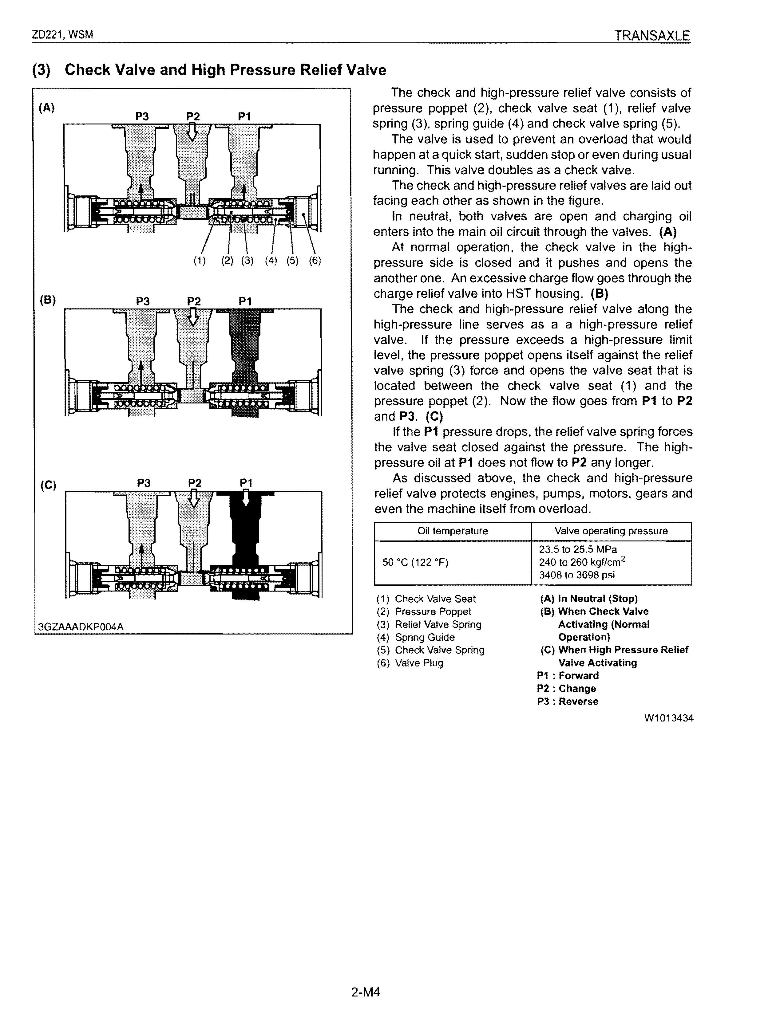
(3) Check Valve and High Pressure Relief Valve
The check and high-pressure relief valve consists of pressure poppet (2), check valve seat (1), relief valve spring (3), spring guide (4) and check valve spring (5).
The valve is used to prevent an overload that would happen at a quick start, sudden stop or even during usual running. This valve doubles as a check valve.
The check and high-pressure relief valves are laid out facing each other as shown in the figure.
In neutral, both valves are open and charging oil enters into the main oil circuit through the valves. (A)
At normal operation, the check valve in the highpressure side is closed and it pushes and opens the another one. An excessive charge flow goes through the charge relief valve into HST housing. (8)
The check and high-pressure relief valve along the high-pressure line serves as a a high-pressure relief valve. If the pressure exceeds a high-pressure limit level, the pressure poppet opens itself against the relief valve spring (3) force and opens the valve seat that is located between the check valve seat (1) and the pressure poppet (2). Now the flow goes from P1 to P2 and P3. (C)
If the P1 pressure drops, the relief valve spring forces the valve seat closed against the pressure. The highpressure oil at P1 does not flow to P2 any longer.
As discussed above, the check and high-pressure relief valve protects engines, pumps, motors, gears and even the machine itself from overload.
(4) Oil Flow
i3GZAAADKPOOSA
(1) Oil Strainer (5) Regulator Valve (5) Check and High Pressure (11) Swash plate
(2) Transmission Case (6) PTa Clutch Relief Valve (12) Piston
(3) Hydraulic Pump
(7) Oil Filter Cartridge (9) Lubricating Orifice (13) Cylinder Block (Motor)
(4) Control Valve (10) Cylinder Block (Pump)
The pump and motor are joined in a closed hydraulic loop and most of oil circulates within the main oil circuit. A little oil lubricates and oozes out from the clearance between the moving parts of the case. Then oil in the main oil circuit of the HST needs to be supplied a want.
The charge oil is sent to the HST housing after the control valve and oil filter pass with the hydraulic pump. The charge oil aids smooth operation of pistons for pump and motor. And overflow oil from HST housing return to the transmission case.
(5) Power Trains Operation
(1) Check and High Pressure (4) Neutral Orifice (7) Motor Relief Valve (5) 011 Filter (8) Lubricating Orifice
(2) High Pressure Relief Valve (6) Regulator Valve (9) Pump
(3) Check Valve
• Neutral
(10) Hydraulic Pump (11) Orifice (To Transmission) (12) Orifice (To Rear Axle Case)
With the control levers in the NEUTRAL position, the piston springs in the pump block in the pumps force the swash plates to a position that is parallel to the pump body. With the swash plates parallel to the pump body, the pistons do not reciprocate in the cylinder block, they merely rotate, and no oil is being drawn in or discharged from the pump. The machine is in a zero displacement position and the machine remains stationary.
Oil returning from the HST housing and hydraulic pump is directed through the regulating valve before returning to the transmission case.
• Forward
As the control levers are pushed forward, the swash plates in the pumps move from the neutral position (parallel to the pump body) to a forward angle position. Piston springs inside the cylinder bores force the pistons against the swash plates_
As the cylinder block rotates, the pistons follow the contour of the swash plate, moving outward, drawing oil into their bores. As the cylinder block continues to rotate, the pistons are forced into their bores, discharging oil under pressure.
High-pressure oil from the pumps is routed to the motors, driving the machine forward.
• Reverse
Reverse operation is accomplished by reversing the angle applied to the pump swash plates, reversing the flow of high-pressure oil to the motors.
(6) Control Linkage
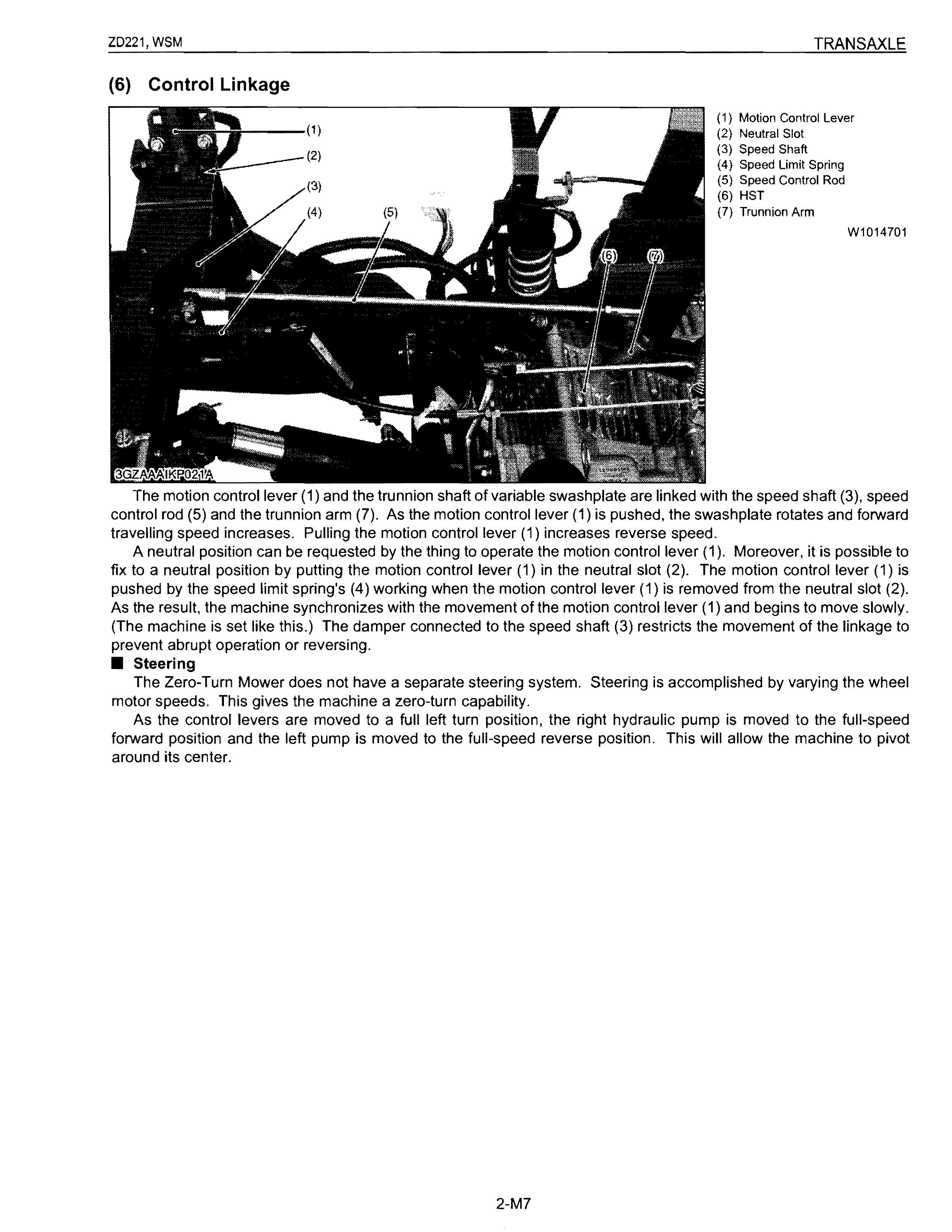
(1) Motion Control Lever
(2) Neutral Slot
(3) Speed Shaft
(4) Speed Limit Spring
(5) Speed Control Rod
(6) HST
(7) Trunnion Arm W1014701
The motion control lever (1) and the trunnion shaft of variable swashplate are linked with the speed shaft (3), speed control rod (5) and the trunnion arm (7). As the motion control lever (1) is pushed, the swashplate rotates and forward travelling speed increases. Pulling the motion control lever (1) increases reverse speed.
A neutral position can be requested by the thing to operate the motion control lever (1). Moreover, it is possible to fix to a neutral position by putting the motion control lever (1) in the neutral slot (2). The motion control lever (1) is pushed by the speed limit spring's (4) working when the motion control lever (1) is removed from the neutral slot (2). As the result, the machine synchronizes with the movement of the motion control lever (1) and begins to move slowly. (The machine is set like this.) The damper connected to the speed shaft (3) restricts the movement of the linkage to prevent abrupt operation or reversing
• Steering
The Zero-Turn Mower does not have a separate steering system. Steering is accomplished by varying the wheel motor speeds. This gives the machine a zero-turn capability.
As the control levers are moved to a full left turn position, the right hydraulic pump is moved to the full-speed forward position and the left pump is moved to the full-speed reverse position. This will allow the machine to pivot around its center.
(7) Final Reduction Gear Section
As for this machine, power is transmitted from the gear on the brake shaft (1) to the rear axle (3) through 70T gear.
(1) Brake Shaft (BT) (3) Rear Axle
(2) 70T Gear
W1014957
3GZAAADKPOOBA
(8) PTO System
•
The ZD series equipped with hydraulic independent PTO clutch (wet multi-plates type). Therefore. the engine power could engage or disengage to the PTO shaft (8) without stopping the machine movement.
The PTO clutch pack (16) has three clutch disks (12), three clutch plates (5), clutch piston (10) and so on. The clutch piston (10) is actuated by hydraulic oil flow the hydraulic pump through regulator valve (14).
3GZAAADKP011A
• Regulator Valve
This machine is controlled with the regulator valve so that the oil sent from the hydraulic pump may become the setting pressure. And the oil flows into oil filter cartridge PTO clutch and hydrostatic transmission.
(Reference)
• Regulator valve setting pressure: 0.5 to 0.7 MPa
5.0 to 7.0 kgf/cm 2 71.2 to 101.1 psi
(1) Poppet
(2) Spring
(3) Plug
A : From Hydraulic Pump to Oil Filter Cartridge, PTO Clutch and Hydrostatic Transmission
B: To Transmission Case
W1015421
• PTO Clutch "Disengaged"
After starting the engine, when the PTO clutch lever is set at the "Disengaged" position, the hole (9) of PTO valve lever (1) dose not face to hydraulic pump port. Since oil from hydraulic pump is blocked at the PTO valve lever (1), oil dose not flow to the PTO shaft. Blocked oil flows to the oil filter cartridge or to the regulator valve.
Oil in the clutch pack drained through the PTO valve lever into the transmission case.
Thus the clutch piston (4) is pushed back by the spring (6). When the piston (4) is pushed back, the piston pushed the brake plate (3) and brake disk, the rotation and drag of the PTO shaft (2) stop.
(1) PTO Valve Lever
(2) PTO Shaft
(3) PTO Brake Plate
A: From Hydraulic Pump
B : To Transmission Case
C : To 011 Filter Cartridge or
(4) Piston Regulator Valve
(5) PTO Clutch Plate
(6) Spring
(7) PTO Brake Disk
(8) PTO Clutch Disk
(9) Hole
W1015803
3GZAAADKP012A
(9) o3GZAAADKP013A
• PTO Clutch "Engaged"
When the PTO clutch lever is set at the "Engaged" position, the PTO clutch valve (1) rotates.
"L" shape oil inner passage in the PTO clutch valve
(1) forms the oil line to the PTO clutch pack.
Oil entering the clutch pack pushes the clutch piston
(4) to engage the clutch pack.
(1) PTO Valve Lever A: From Hydraulic Pump
(2) PTO Shaft B : To PTa Shaft
(3) PTO Brake Plate C : To PTa Pipe
(4) Piston
(5) PTO Clutch Plate
(6) Spring
(7) PTO Brake Disk
(8) PTO Clutch Disk
(9) Oil Inner Passage
W1016171
3GZAAADKP012B
3GZAAADKP014A
(1) Brake Pedal (5) Brake Rod (8) Brake Spring (11) Brake Disk
(2) Parking Lock Pedal (6) Brake Assembly (9) Ball (12) Brake Plate
(3) Brake Pedal Return Spring (7) Brake Arm (10) Actuator (13) HST Motor Shaft (Brake)
(4) Brake Shaft
The parking brake is composed of brake pedal (1), parking lock pedal (2), brake pedal return spring (3), brake shaft (4), brake rods (5), brake arms (7) and brake assemblies (6).
The brake is mechanical wet disks type.
When the brake pedal (1) is pressed, the brake shaft (4) is rotated forward and the brake rods (5) is pulled forward. And the brake arms (7) are rotated forward.
The brake arms (7) is connected mechanically to the grooves of the actuators (10).
The brake arms (7) rotates the actuators (10) and the actuators (10) mounting on three balls pushes the brake disks (11) and brake plates (12) to stop the brake shafts rotation.
As both the brake pedal (1) and parking lock pedal (2) are pressed, the parking brake will be applied and locked.