2 minute read
4. CHECKING, DISASSEMBLING AND SERVICING [1]


Checking And Adjusting
(1) Engine Body
Compression Pressure
1. Run the engine until it is warmed up.
2. Stop the engine.
3. Remove the air cleaner, the muffler and all glow plugs (or nozzles).
4. Set a compression tester with the adaptor to the glow plug hole (or nozzle hole).
Nozzle hole: Adaptor H (07909-31231)
Glow plug hole: Adaptor L (07909-31301)
5. After making sure that the stop lever is set at the stop position (non-injection), run the engine with the starter and measure the compression pressure.
6. Repeat steps 4 and 5 for each cylinder.
7. If the measurement is below the allowable limit, apply a small amount of oil to the cylinder wall through the glow plug hole (or nozzle hole) and measure the compression pressure again.
8. If the compression pressure is still less than the allowable limit, check the top clearance, valve clearance and cylinder head.
9. If the compression pressure increases after applying oil, check the cylinder wall and piston rings
• NOTE
• Check the compression pressure with the specified valve clearance.
• Always use a fully charged battery for performing this test.
• Variances in cylinder compression values should be under 10 %.
Valve Clearance
• IMPORTANT
• Valve clearance must be checked and adjusted when engine is cold.
1. Remove the cylinder head cover and the glow plugs.
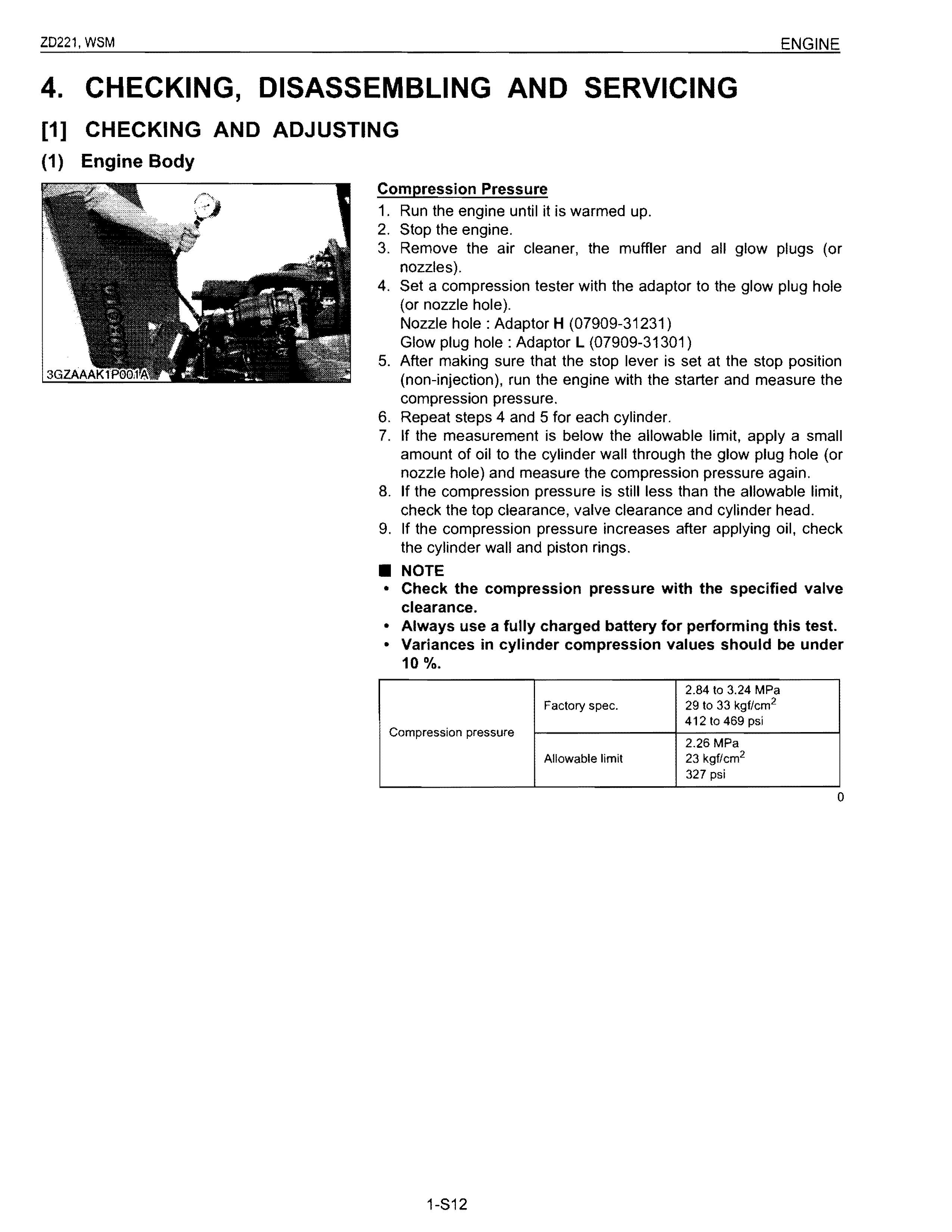
2. Align the "1TC" mark (1) on the flywheel and alignment mark so that the No.1 piston comes to the compression top dead center.
3. Check the following valve clearance marked with "1r" using a thickness gauge.
4. If the clearance is not within the factory specifications, adjust with the adjusting screw.
5. Then turn the flywheel 6.28 rad (360°). and align the "1TC" mark (1) on the flywheel and alignment mark so that the No.1 piston comes to the overlap position.
6. Check the following valve clearance marked with "1r" using a feeler gauge.
• NOTE
• The sequence of cylinder numbers is given as No.1, No.2 and No.3 starting from the gear case side.
• After adjusting the valve clearance, secure the adjusting screw with the lock nut.
(1) "1TC" Mark (2)
Mark Plate
(2) Lubricating System
Engine Oil Pressure
1. Remove the engine oil pressure switch, and set an oil pressure tester.
2. Start the engine. After warming up, measure the oil pressure of both idling and rated speeds.
3. If the oil pressure is less than the allowable limit, check the following.
• Engine oil insufficient
• Oil pump defective
• Oil strainer clogged
3G FABAB 1P056A
• Oil filter cartridge clogged
• Oil gallery clogged
• Excessive oil clearance
• Foreign matter in the relief valve
At idle speed Factory spec.
(3) Cooling System
Engine oil pressure
(When reassembling)
At rated speed
Factory spec.
Allowable limit
More than 49 kPa 0.50 kgf/cm 2 7.1 psi
197 to 441 kPa 2.00 to 4.50 kgf/cm 2 28.5 to 64.0 psi
147 kPa 1.50 kgf/cm 2 21.3 psi
• After checking the engine oil pressure, tighten the engine oil pressure switch to the specified torque.
15 to 19 N'm
Tightening torque Oil pressure switch 1.5 to 2.0 kgf·m 11 to 141bHt
Fan Belt Tension
1. Measure the deflection (A), depressing the belt halfway between the fan drive pulley and alternator pulley at specified force 98 N (10 kgf, 22 Ibf).
2. If the measurement is not within the factory specifications, loosen the alternator mounting screws and relocate the alternator to adjust.
7.0 to 9.0 mm
Deflection (A) Factory spec. 0.28 to 0.35 in.
(A) Deflection