25 minute read
CHECK POINTS OF INITIAL 50 HOURS


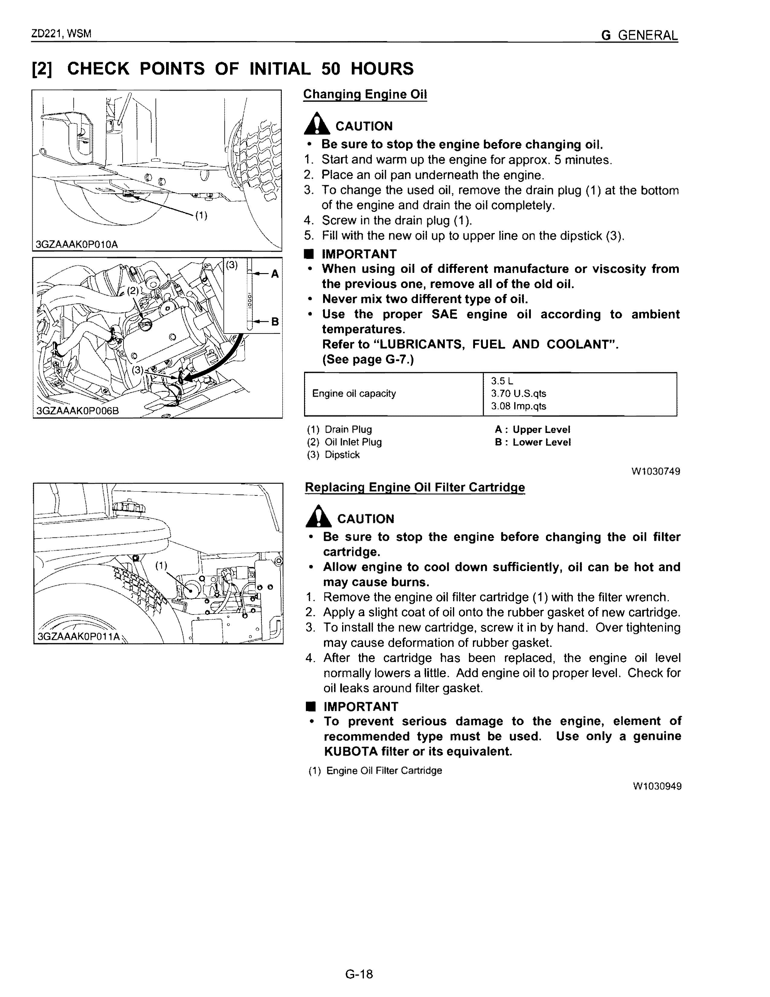
Changing Engine Oil
Acaution
• Be sure to stop the engine before changing oil.
1. Start and warm up the engine for approx. 5 minutes.
2. Place an oil pan underneath the engine.
3. To change the used oil, remove the drain plug (1) at the bottom of the engine and drain the oil completely.
4. Screw in the drain plug (1).
5. Fill with the new oil up to upper line on the dipstick (3).
3GZAAAKOP010A
• IMPORTANT
• When using oil of different manufacture or viscosity from the previous one, remove all of the old oil.
• Never mix two different type of oil.
• Use the proper SAE engine oil according to ambient temperatures. Refer to "LUBRICANTS, FUEL AND COOLANT".
(See page G-7.)
Engine oil capacity
(1) Drain Plug
(2) Oil Inlet Plug
(3) Dipstick
A: Upper Level
B : Lower Level
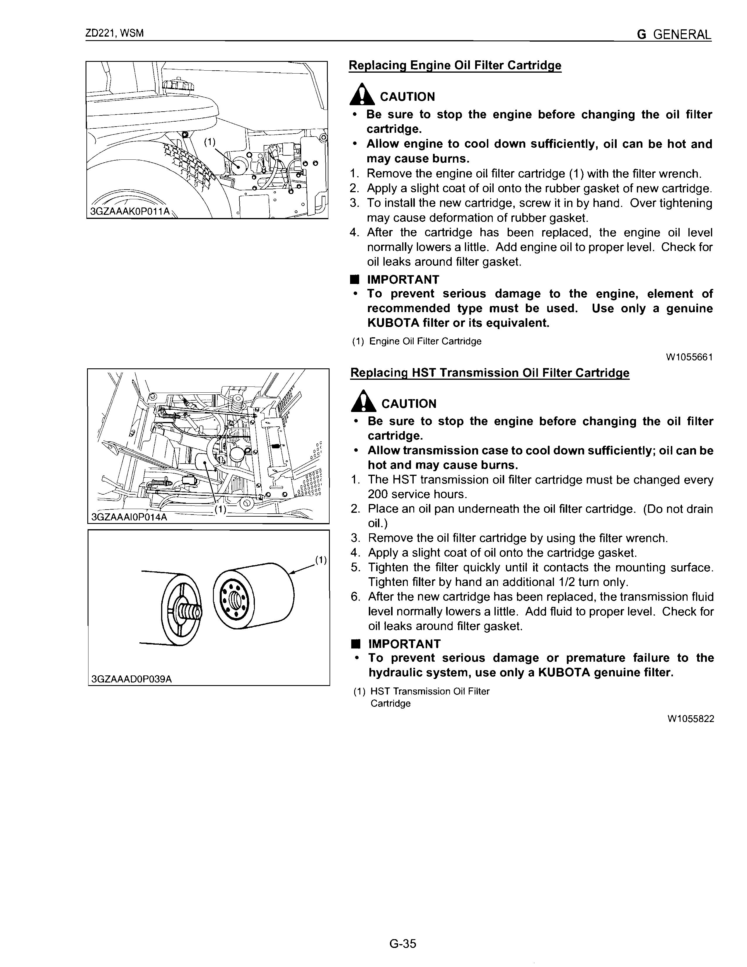
Replacing Engine Oil Filter Cartridge
ACAUTION
W1030749
• Be sure to stop the engine before changing the oil filter cartridge.
• Allow engine to cool down suffiCiently, oil can be hot and may cause burns.
1. Remove the engine oil filter cartridge (1) with the filter wrench.
2. Apply a slight coat of oil onto the rubber gasket of new cartridge.
3. To install the new cartridge, screw it in by hand. Over tightening may cause deformation of rubber gasket.
4. After the cartridge has been replaced, the engine oil level normally lowers a little. Add engine oil to proper level. Check for oil leaks around filter gasket.
• IMPORTANT
• To prevent serious damage to the engine, element of recommended type must be used. Use only a genuine KUBOTA filter or its equivalent.
(1) Engine Oil Filter Cartridge
W1030949
Replacing HST Transmission Oil Filter Cartridge
Acaution
• Be sure to stop the engine before changing the oil filter cartridge.
• Allow transmission case to cool down sufficiently; oil can be hot and may cause burns.
1. The HST transmission oil filter cartridge must be changed every 200 service hours.
2. Place an oil pan underneath the oil filter cartridge. (Do not drain oil. )
3. Remove the oil filter cartridge by using the filter wrench.
4. Apply a slight coat of oil onto the cartridge gasket.
5. Tighten the filter quickly until it contacts the mounting surface. Tighten filter by hand an additional 1/2 turn only.
6. After the new cartridge has been replaced, the transmission fluid level normally lowers a little. Add fluid to proper level. Check for oil leaks around filter gasket.
• IMPORTANT
• To prevent serious damage or premature failure to the hydraulic system, use only a KUBOTA genuine filter.
(1) HST Transmission Oil Filter Cartridge
W1031068
Check Point Of Initial 400 Hours
Replacing Transmission Oil Filter Cartridge
Acaution
• Be sure to stop the engine before changing the oil filter cartridge.
• Allow transmission case to cool down sufficiently; oil can be hot and may cause burns.
1. The oil filter cartridge must be changed every 400 service hours.
2. To drain the transmission oil. place oil pan underneath the transmission case and the rear axle gear case (RH and LH) and remove the drain plug at the bottom of the transmission case and the rear axle gear case (RH and LH).
3. After draining, reinstall the drain plugs.
4. Remove the oil filter cartridge by using the filter wrench.
5. Apply a slight coat of oil onto the cartridge gasket.
6. Tighten the filter quickly until it contacts the mounting surface. Tighten filter by hand an additional 1/2 tum only.
7. After the new cartridge has been replaced, the transmission fluid level normally lowers a little. Add fluid to proper level. Check for oil leaks around filter gasket.
• IMPORTANT
3GZAAABOP019B
• To prevent serious damage or premature failure to the hydraulic system, use only a KUBOTA genuine filter.
(1) Transmission Oil Filter Cartridge
W1051648
Changing Transmission Fluid and Rear Axle Gear Case Oil (RH and LH)
Acaution
• Be sure to stop the engine and remove the key before changing or checking the oil.
• Allow transmission case to cool down sufficiently; oil can be hot and may cause burns. The fluid in the transmission case is also used for the hydrostatic drive system.
1. To drain the transmission oil, place oil pan underneath the transmission case and remove the drain plug at the bottom of the transmission case.
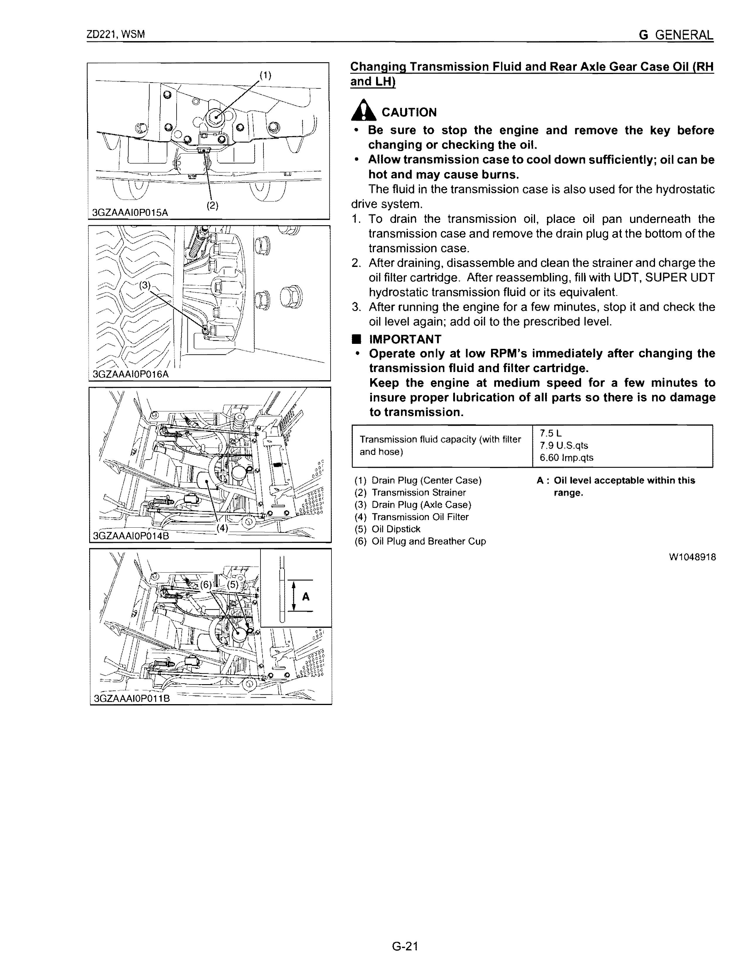
2. After draining, disassemble and clean the strainer and charge the oil filter cartridge. After reassembling, fill with UDT. SUPER UDT hydrostatic transmission fluid or its equivalent.
3. After running the engine for a few minutes, stop it and check the oil level again; add oil to the prescribed level.
• IMPORTANT
• Operate only at low RPM's immediately after changing the transmission fluid and filter cartridge. Keep the engine at medium speed for a few minutes to insure proper lubrication of all parts so there is no damage to transmission.
Transmission fluid capacity (with filter and hose)
(1) Drain Plug (Center Case)
(2) Transmission Strainer
(3) Drain Plug (Axle Case)
(4) Transmission Oil Filter
(5) Oil Dipstick
(6) Oil Plug and Breather Cup
7.5 L
7.9 U.S.qts 6.60 Imp.qts
A: Oil level acceptable within this range.
W1048918
Cleaning Transmission Oil Strainer
1. When changing the transmission fluid, disassemble and rinse the strainer with nonflammable solvent to completely clean off filings.
2. Check O-rings, replace if damaged, cracked or hardened. When reassembling be careful not to damage the parts
• NOTE
• Since the fine filings in the oil can damage the precision component parts of the hydraulic system, the end of the suction line is provided with an oil strainer.
[4] CHECK POINTS OF EVERY 50 HOURS
Checking Safety Device
A. CAUTION
• Do not allow anyone near the machine while testing.
• If the machine does not pass one of the following tests, do not operate the machine.
• Sit on operator's seat for all tests except for Test 1.
• IMPORTANT
• Check the following tests before operating the machine.
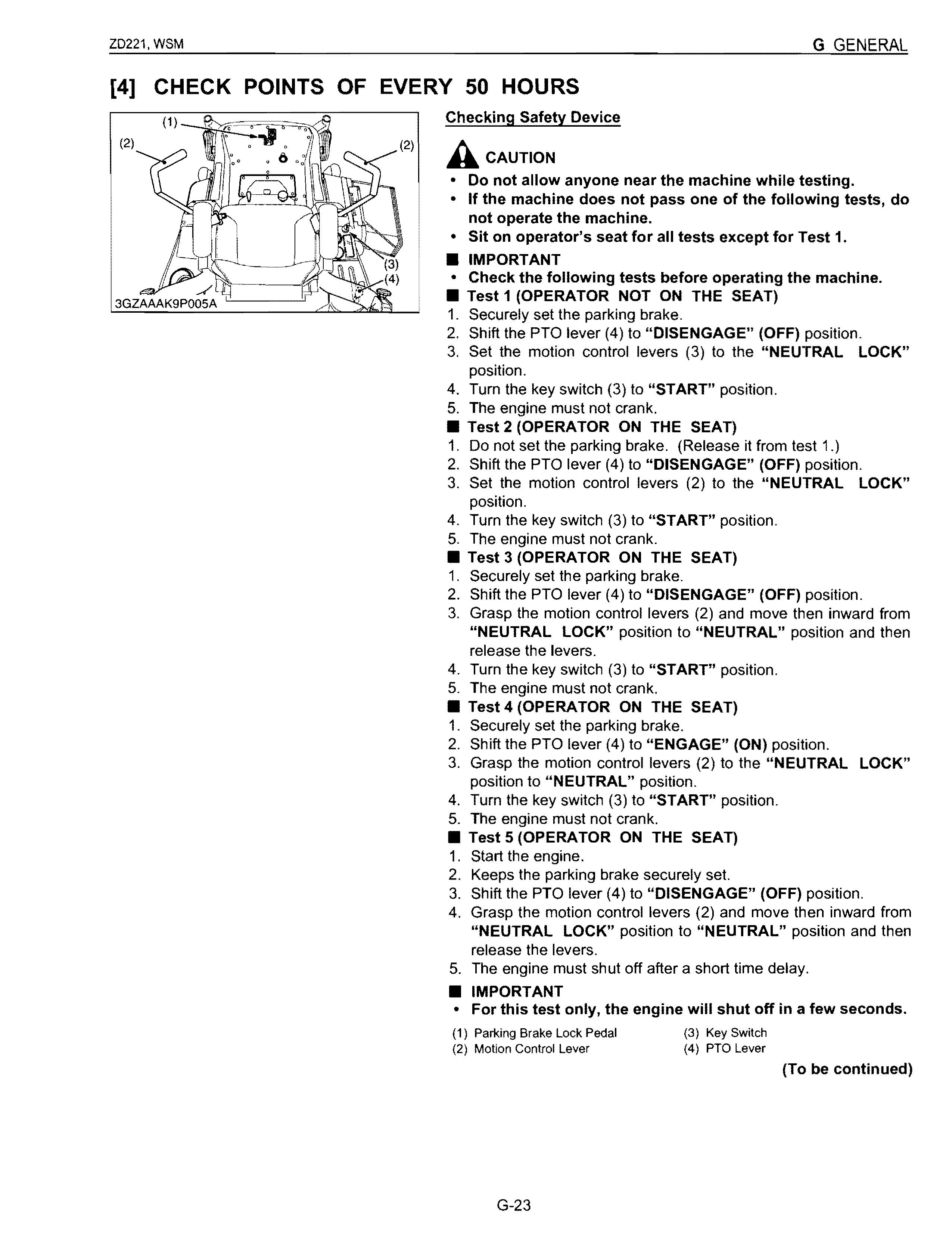
• Test 1 (OPERATOR NOT ON THE SEAT)
1. Securely set the parking brake.
2. Shift the PTO lever (4) to "DISENGAGE" (OFF) position.
3. Set the motion control levers (3) to the "NEUTRAL LOCK" position.
4. Turn the key switch (3) to "START" position.
5. The engine must not crank.
• Test 2 (OPERATOR ON THE SEAT)
1. Do not set the parking brake. (Release it from test 1.)
2. Shift the PTO lever (4) to "DISENGAGE" (OFF) position.
3. Set the motion control levers (2) to the "NEUTRAL LOCK" position.
4. Turn the key switch (3) to "START" position.
5. The engine must not crank.
• Test 3 (OPERATOR ON THE SEAT)
1. Securely set the parking brake.
2. Shift the PTO lever (4) to "DISENGAGE" (OFF) position.
3. Grasp the motion control levers (2) and move then inward from "NEUTRAL LOCK" position to "NEUTRAL" position and then release the levers.
4. Turn the key switch (3) to "START" position.
5. The engine must not crank.
• Test 4 (OPERATOR ON THE SEAT)
1. Securely set the parking brake.
2. Shift the PTO lever (4) to "ENGAGE" (ON) position.
3. Grasp the motion control levers (2) to the "NEUTRAL LOCK" position to "NEUTRAL" position.
4. Turn the key switch (3) to "START" position.
5. The engine must not crank.
• Test 5 (OPERATOR ON THE SEAT)
1. Start the engine.
2. Keeps the parking brake securely set.
3. Shift the PTO lever (4) to "DISENGAGE" (OFF) position.
4. Grasp the motion control levers (2) and move then inward from "NEUTRAL LOCK" position to "NEUTRAL" position and then release the levers.
5. The engine must shut off after a short time delay.
• IMPORTANT
• For this test only, the engine will shut off in a few seconds.
(1) Parking Brake Lock Pedal
(2) Motion Control Lever
(3) Key Switch (4) PTO Lever
(To be continued)
• Test 6 (OPERATOR ON THE SEAT)
1. Start the engine.
2. Do not set the parking brake.
3. Shift the PTO lever (4) to "DISENGAGE" (OFF) position.
4. Grasp the motion control levers (2) and move then inward from "NEUTRAL LOCK" position to "NEUTRAL" position and then release the levers.
5. Stand up. (Do not get off the machine.)
6. The engine must shut off
• Test 7 (OPERATOR ON THE SEAT)
1. Start the engine.
2. Do not set the parking brake.
3. Shift the PTO lever (4) to "ENGAGE" (ON) position.
4. Stand up. (Do not get off the machine.)
5. The engine must shut off.
(1) Parking Brake Lock Pedal
(2) Motion Control Lever
(3) Key Switch
(4) PTO Lever
W1050412
3GZAAAIOP018A
Greasing
1. Apply a grease to the following positions as figures.
A Caution
• Be sure to stop the engine and remove the key before greasing.
(1) Front Axle (LH, RH)
(2) Front Wheel (LH, RH)
(4) Machine Universal Joint
(5) Seat Adjuster
3GZAAAKOP012A
(3) Parking Brake Lock Pedal G-25
(To be continued)
1. Apply a grease to the following position as figures.
A Caution
• Be sure to stop the engine and remove the key before greasing.
(6) Seat Adjuster
(7) Throttle Cable (Oil)
W1034228
! 3GZAAAIOP018B
Oiling
1. Apply oil to the following positions as figures.
A Caution
• Be sure to stop the engine and remove the key before greasing.
(1) Front Lift Arm (LH, RH)
(2) Motion Control Lever Pivot Bushing (LH, RH)
(3) Bushing
(4) Motion Control Lever Contact Position (LH, RH)
(5) Lift Control Cable (Oil)
(To be continued)
1 Apply oil to the following positions as figures.
A Caution
• Be sure to stop the engine and remove the key before greasing.
(6) Throttle Cable (Oil)
(7) Throttle Cable (Oil)
W1048721
Checking Gear Box Oil Level
A Caution
Always stop the engine and remove the key before checking oil.
1. Park the machine on a flat surface and lower the mower to the ground.
To check the oil level, loosen check plug bolt and check to see that the oil level is just below the check plug port. If the level is too low, add new oil to the prescribed level at the oil inlet.
(See page G-7.)
(1) Drain Plug (Bolt)
(2) Check Plug (Bolt)
W1054012
[5] CHECK POINTS OF EVERY 100 HOURS
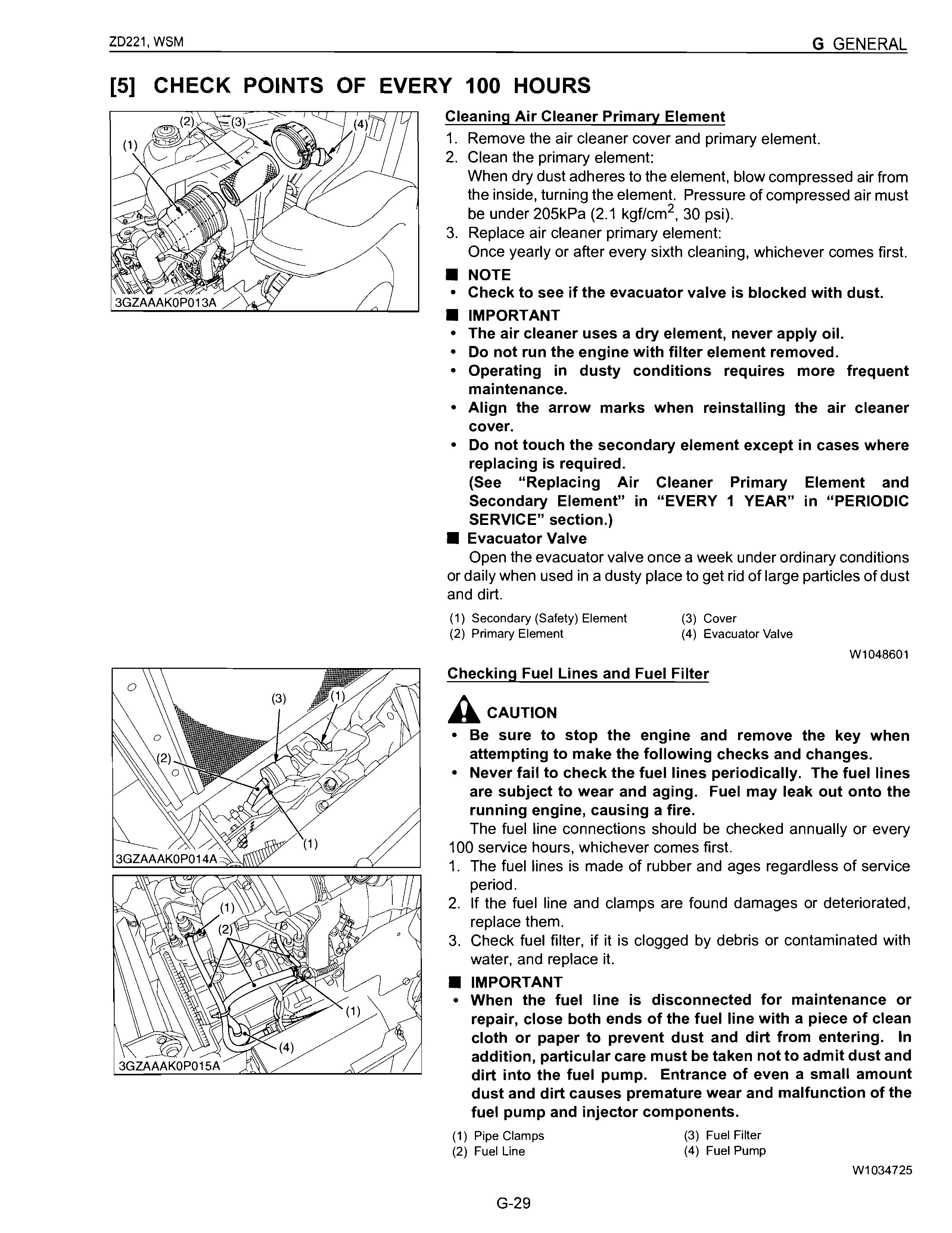
Cleaning Air Cleaner Primary Element
1. Remove the air cleaner cover and primary element.
2. Clean the primary element: When dry dust adheres to the element, blow compressed air from the inside, turning the element. Pressure of compressed air must be under 205kPa (2.1 kgf/cm 2 , 30 psi).
3. Replace air cleaner primary element: Once yearly or after every sixth cleaning, whichever comes first.
• NOTE
• Check to see if the evacuator valve is blocked with dust.
• IMPORTANT
• The air cleaner uses a dry element, never apply oil.
• Do not run the engine with filter element removed.
• Operating in dusty conditions requires more frequent maintenance.
• Align the arrow marks when reinstalling the air cleaner cover.
• Do not touch the secondary element except in cases where replacing is required.
(See "Replacing Air Cleaner Primary Element and Secondary Element" in "EVERY 1 YEAR" in "PERIODIC SERVICE" section.)
• Evacuator Valve
Open the evacuator valve once a week under ordinary conditions or daily when used in a dusty place to get rid of large particles of dust and dirt.
(1) Secondary (Safety) Element
(2) Primary Element
(3) Cover
(4) Evacuator Valve
Checking Fuel Lines and Fuel Filter
A Caution
W1048601
• Be sure to stop the engine and remove the key when attempting to make the following checks and changes.
• Never fail to check the fuel lines periodically. The fuel lines are subject to wear and aging. Fuel may leak out onto the running engine, causing a fire.
The fuel line connections should be checked annually or every 100 service hours, whichever comes first.
1. The fuel lines is made of rubber and ages regardless of service period.
2. If the fuel line and clamps are found damages or deteriorated, replace them.
3. Check fuel filter, if it is clogged by debris or contaminated with water, and replace it.
• IMPORTANT
• When the fuel line is disconnected for maintenance or repair, close both ends of the fuel line with a piece of clean cloth or paper to prevent dust and dirt from entering. In addition, particular care must be taken not to admit dust and dirt into the fuel pump. Entrance of even a small amount dust and dirt causes premature wear and malfunction of the fuel pump and injector components.
Adjusting Fan Belt Tension
Acaution
• Be sure to stop the engine and remove the key before checking belt tension.
1. If the fan drive belt becomes loose, the engine may overheat.
2. To adjust, loosen bolts and turn the alternator to tighten the belt.
3. After adjustment, securely tighten the bolts.
Moderate belt tension:
The belt deflect approx. 10 mm (0.4 in.) when the center of the belt is depressed with finger pressure of 98 N (10 kgf, 22 Ibf).
Fan belt tension (A)
• IMPORTANT
Factory spec. Approx. 10 mm 0.4 in
• When replacing fan belt, be careful not to catch it on the cap under the water pump. See the illustration to the left.
(1) Tension Bolt
(2) Alternator
(3) Adjustment Bolt
W1037821
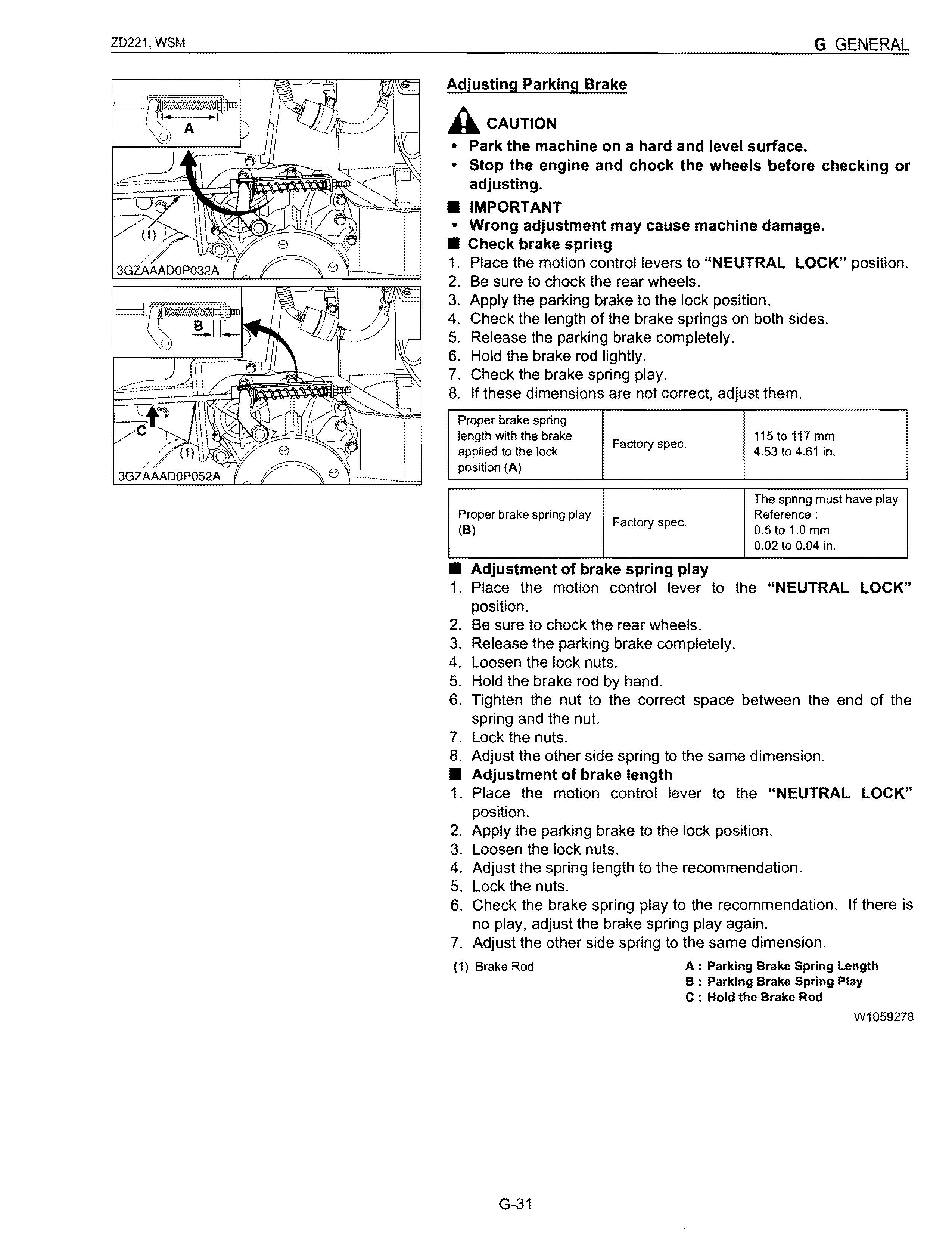
Adjusting Parking Brake A CAUTION
• Park the machine on a hard and level surface.
• Stop the engine and chock the wheels before checking or adjusting.
• IMPORTANT
• Wrong adjustment may cause machine damage.
• Check brake spring
1. Place the motion control levers to "NEUTRAL LOCK" position.
2. Be sure to chock the rear wheels.
3. Apply the parking brake to the lock position.
4. Check the length of the brake springs on both sides.
5. Release the parking brake completely.
6. Hold the brake rod lightly.
7. Check the brake spring play.
8. If these dimensions are not correct, adjust them.
Proper brake spring length with the brake Factory spec. 115 to 117 mm applied to the lock 4.53 to 4,61 in. position (A)
The spring must have play
Proper brake spring play Factory spec, Reference: (B) 0.5 to 1.0 mm 0.02 to 0.04 in.
• Adjustment of brake spring play
1. Place the motion control lever to the "NEUTRAL LOCK" position.
2. Be sure to chock the rear wheels.
3. Release the parking brake completely.
4. Loosen the lock nuts.
5. Hold the brake rod by hand.
6. Tighten the nut to the correct space between the end of the spring and the nut.
7. Lock the nuts.
8. Adjust the other side spring to the same dimension.
• Adjustment of brake length
1. Place the motion control lever to the "NEUTRAL LOCK" position.
2. Apply the parking brake to the lock position.
3. Loosen the lock nuts.
4. Adjust the spring length to the recommendation.
5. Lock the nuts.
6. Check the brake spring play to the recommendation. If there is no play, adjust the brake spring play again.
7. Adjust the other side spring to the same dimension.
(1) Brake Rod
A : Parking Brake Spring Length
B : Parking Brake Spring Play
C : Hold the Brake Rod
W1059278
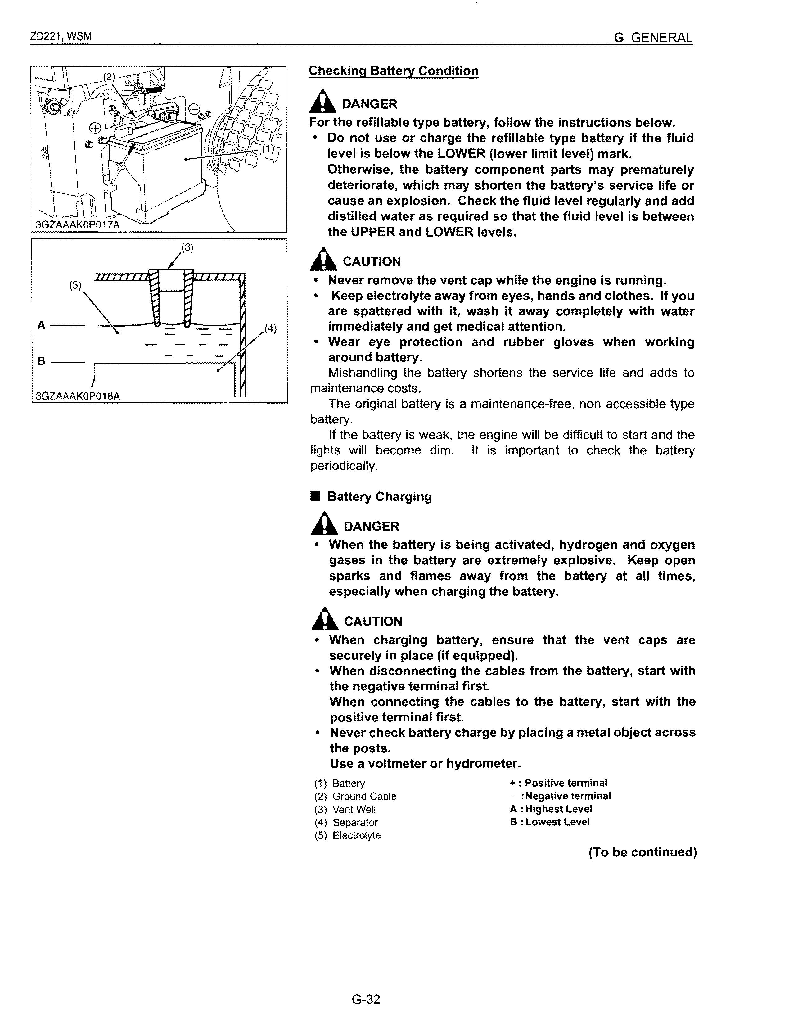
Checking Battery Condition A DANGER
For the refillable type battery, follow the instructions below.
• Do not use or charge the refillable type battery if the fluid level is below the LOWER (lower limit level) mark. Otherwise, the battery component parts may prematurely deteriorate, which may shorten the battery's service life or cause an explosion. Check the fluid level regularly and add distilled water as required so that the fluid level is between the UPPER and LOWER levels.
Acaution
• Never remove the vent cap while the engine is running.
• Keep electrolyte away from eyes, hands and clothes. If you are spattered with it, wash it away completely with water immediately and get medical attention.
• Wear eye protection and rubber gloves when working around battery.
Mishandling the battery shortens the service life and adds to maintenance costs.
The original battery is a maintenance-free, non accessible type battery.
If the battery is weak, the engine will be difficult to start and the lights will become dim. It is important to check the battery periodically
• Battery Charging A DANGER
• When the battery is being activated, hydrogen and oxygen gases in the battery are extremely explosive. Keep open sparks and flames away from the battery at all times, especially when charging the battery.
Acaution
• When charging battery, ensure that the vent caps are securely in place (if equipped).
• When disconnecting the cables from the battery, start with the negative terminal first.
When connecting the cables to the battery, start with the positive terminal first.
• Never check battery charge by placing a metal object across the posts.
Use a voltmeter or hydrometer.
(For accessible maintainable type batteries with removable vent caps.)
1. Make sure each electrolyte level is at the bottom of vent wells, if necessary add distilled water in a well-ventilated area.
2. The water in the electrolyte evaporates during recharging. Liquid shortage damages the battery. Excessive liquid spills over and damages the machine body.
3. To slow charge the battery, connect the battery positive terminal to the charger positive terminal and the negative to the negative, then recharge in the standard fashion.
4. A boost charge is only for emergencies. It will partially charge the battery at a higher rate and in a short time.
When using a boost-charged battery, it is necessary to recharge the battery as soon as possible. Failure to do this will shorten the battery's service life.
5. When the specific gravity of electrolyte reaches 1.27 to 1.29, charge has completed.
6. When exchanging an old battery with new one, use a battery of equal specification shown in.
Reserve Cold Battery type Volts (V) capacity cranking (min) Amps 51R 12 70 450
(For non-accessible maintenance-free type batteries.)
Maintenance-free, non-accessible batteries are designed to eliminate the need to add water. Yet the volume of electrolyte above plates may eventually become depleted due to abnormal conditions such as high heat or improper regulator setting. Use a voltmeter to check the state of charge. (See reference chart to determine if charging is necessary.)
[6] CHECK POINTS OF EVERY 150 HOURS
Changing Mower Gear Box Oil
ACAUTION
• Be sure to stop the engine and remove the ley before changing the oil.
1. To drain the used oil, remove the drain plug (1) and the oil filter plug (3) at the gear box and drain the oil completely into the oil pan.
2. After draining reinstall the drain plug (1).
3. Remove the oil level check plug (2).
3GZAAAKOP019A
4. Fill with the new oil up to the check plug port. (See "LUBRICANTS AND FUEL" in this section.)
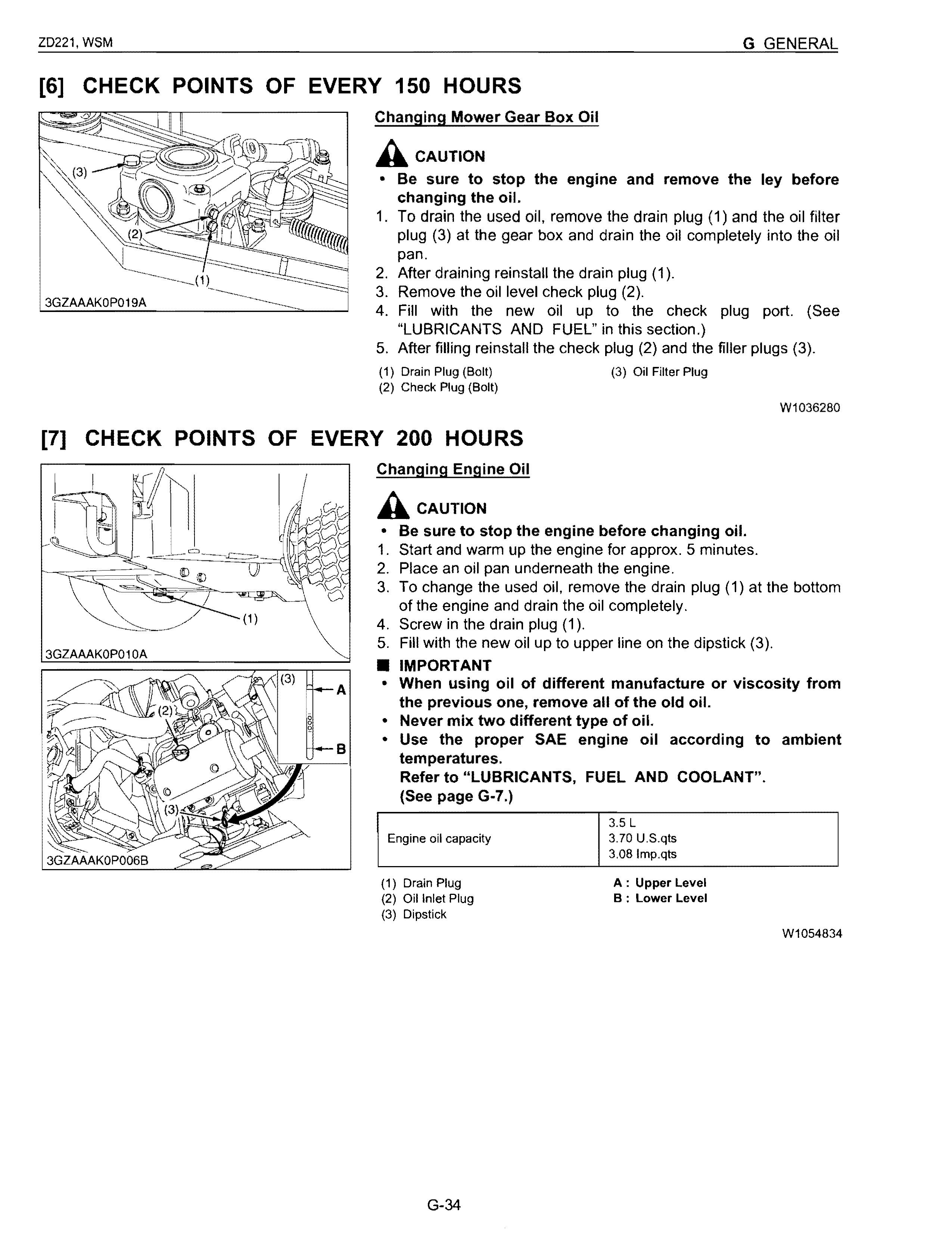
5. After filling reinstall the check plug (2) and the filler plugs (3).
(1) Drain Plug (Bolt)
(2) Check Plug (Bolt)
[7] CHECK POINTS OF EVERY 200 HOURS
Changing Engine Oil
ACAUTION
3GZAAAKOPO 1OA
(3) Oil Filter Plug
W1036280
• Be sure to stop the engine before changing oil.
1. Start and warm up the engine for approx. 5 minutes.
2. Place an oil pan underneath the engine.
3. To change the used oil, remove the drain plug (1) at the bottom of the engine and drain the oil completely.
4. Screw in the drain plug (1).
5. Fill with the new oil up to upper line on the dipstick (3).
• IMPORTANT
• When using oil of different manufacture or viscosity from the previous one, remove all of the old oil.
• Never mix two different type of oil.
• Use the proper SAE engine oil according to ambient temperatures. Refer to "LUBRICANTS, FUEL AND COOLANT", (See page G-7.)
(1) Drain Plug
(2) Oil Inlet Plug
(3) Dipstick
Replacing Engine Oil Filter Cartridge
ACAUTION
• Be sure to stop the engine before changing the oil filter cartridge.
• Allow engine to cool down sufficiently, oil can be hot and may cause burns.
1. Remove the engine oil filter cartridge (1) with the filter wrench.
2. Apply a slight coat of oil onto the rubber gasket of new cartridge.
3. To install the new cartridge, screw it in by hand. Over tightening may cause deformation of rubber gasket.
4. After the cartridge has been replaced, the engine oil level normally lowers a little. Add engine oil to proper level. Check for oil leaks around filter gasket.
• IMPORTANT
• To prevent serious damage to the engine, element of recommended type must be used. Use only a genuine KUBOTA filter or its equivalent.
(1) Engine Oil Filter Cartridge
Replacing HST Transmission Oil Filter Cartridge
ACAUTION
W1055661
• Be sure to stop the engine before changing the oil filter cartridge.
• Allow transmission case to cool down sufficiently; oil can be hot and may cause burns.
1. The HST transmission oil filter cartridge must be changed every 200 service hours.
2. Place an oil pan underneath the oil filter cartridge. (Do not drain oil.)
3. Remove the oil filter cartridge by using the filter wrench.
4. Apply a slight coat of oil onto the cartridge gasket.
5. Tighten the filter quickly until it contacts the mounting surface. Tighten filter by hand an additional 1/2 turn only.
6. After the new cartridge has been replaced, the transmission fluid level normally lowers a little. Add fluid to proper level. Check for oil leaks around filter gasket.
• IMPORTANT
• To prevent serious damage or premature failure to the hydraulic system, use only a KUBOTA genuine filter.
(1)
W1055822
3GZAAAIOP043B
Adjusting Motion Control Lever Pivot
Acaution
• Be sure to stop the engine and set the parking brake to "ON" before checking.
Lever free travel (A) Factory spec. 2 to 15 mm
0.08 to 0.59 in.
1. Set the motion control lever (1) in the "NEUTRAL" position.
2. Slightly move the lever back and forth and measure the free travel at the top of lever stroke.
3. If the free travel limits are exceeded, remove the fender and retighten the nut (3) to specified torque.
• NOTE
• If the motion control lever pivot bolt (2) is maladjusted, speed control may be difficult.
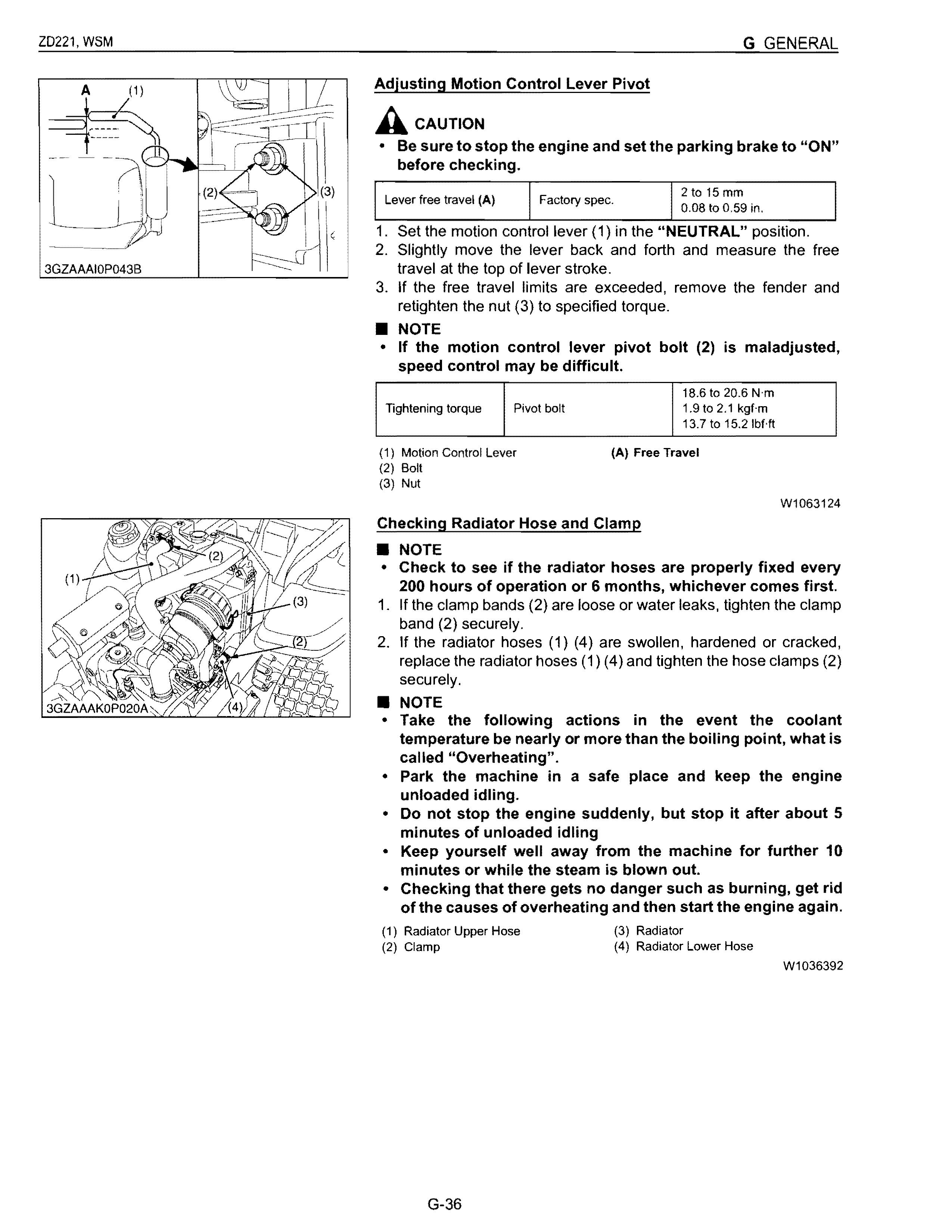
18.6 to 20.6 N'm
Tightening torque Pivot bolt 1.9t02.1 kgf-m 13.7 to 15.21bHt
(1) Motion Control Lever
(2) Bolt
(3) Nut
(A) Free Travel
Checking Radiator Hose and Clamp
• NOTE
W1063124
• Check to see if the radiator hoses are properly fixed every 200 hours of operation or 6 months, whichever comes first.
1. If the clamp bands (2) are loose or water leaks, tighten the clamp band (2) securely.
2. If the radiator hoses (1) (4) are swollen, hardened or cracked, replace the radiator hoses (1) (4) and tighten the hose clamps (2) securely.
• NOTE
• Take the following actions in the event the coolant temperature be nearly or more than the boiling point, what is called "Overheating".
• Park the machine in a safe place and keep the engine unloaded idling.
• Do not stop the engine suddenly, but stop it after about 5 minutes of unloaded idling
• Keep yourself well away from the machine for further 10 minutes or while the steam is blown out.
• Checking that there gets no danger such as burning. get rid of the causes of overheating and then start the engine again.
(1) Radiator Upper Hose
(2) Clamp
(3) Radiator
Radiator Lower Hose
W1036392
Checking Hydraulic Hose
A Caution
• Be sure to stop the engine and remove the key before checking and replacing hydraulic hose.
• Allow transmission case to cool down sufficiently; oil can be hot and may cause burns.
1. Check to see the hose is tight and not damaged.
2. If the worn or damaged of the hose is found, replace it.
(1) Mower Lift Cylinder Hose
Checking Intake Air Line
W1036641
1. Check to see that hoses and hose clamps are tight and not damaged.
2. If hoses and clamps are found worn or damaged, replace or repair them at once.
(1) Hose (2) Clamp
W1037686
Check Point Of Every 400 Hours
Replacing Fuel Filter Elements
• IMPORTANT
• This job should not be done in the field, but in a clean place.
1. Place an oil pan under the fuel filter element (3) (4).
2. Loosen the pipe clamps (1).
3. Remove the fuel filter element (3) (4) and close the fuel line (2) with a clean pins quickly.
4. Replace the fuel filter elements with KUBOTA genuine filter elements.
5. Clean the leaked fuel with a waste.
6. Bleed the fuel system.
(1) Pipe Clamp
(2) Fuel Line
(3) Fuel Filter Element 1
(4) Fuel Filter Element 2 W1040109
Check Point Of Every 1500 Hours
Checking Fuel Injection Nozzle Injection Pressure
1. Set the injection nozzle to a nozzle tester.
2. Slowly move the tester handle to measure the pressure at which fuel begins jetting out from the nozzle.
3. If the measurement is not within the factory specifications, replace the adjusting washer (1) in the nozzle holder to adjust it.
(Reference)
• Pressure variation with 0.01 mm (0.0004 in.) difference of adjusting washer thickness.
Approx. 235 kPa (2.4 kgf/cm 2 , 34 psi)
13.73 to 14.70 MPa
Fuel injection pressure Factory spec. 140.0 to 150.0 kgf/cm 2 1991 to 2133 psi
(1) Adjusting Washer
3EEABAB1P171B
[10] CHECK POINT OF EVERY 3000 HOURS
Checking Injection Pump
• Fuel Tightness of Pump Element
1. Remove the engine stop solenoid.
2. Remove the injection pipes and glow plugs.
3. Install the injection pump pressure tester to the injection pump.
4. Install the injection nozzle (2) jetted with the proper injection pressure to the injection pump pressure tester (1). (Refer to the photo.)
5. Set the speed control lever to the maximum speed position.
6. Run the starter to increase the pressure.
7. If the pressure can not reach the allowable limit, replace the pump with new one or repair with a Kubota-authorized pump service shop.
13.73 MPa
Allowable limit 140.0 kgf/cm 2 element 1991 psi
Fuel tightness of pump
• Fuel Tightness of Delivery Valve
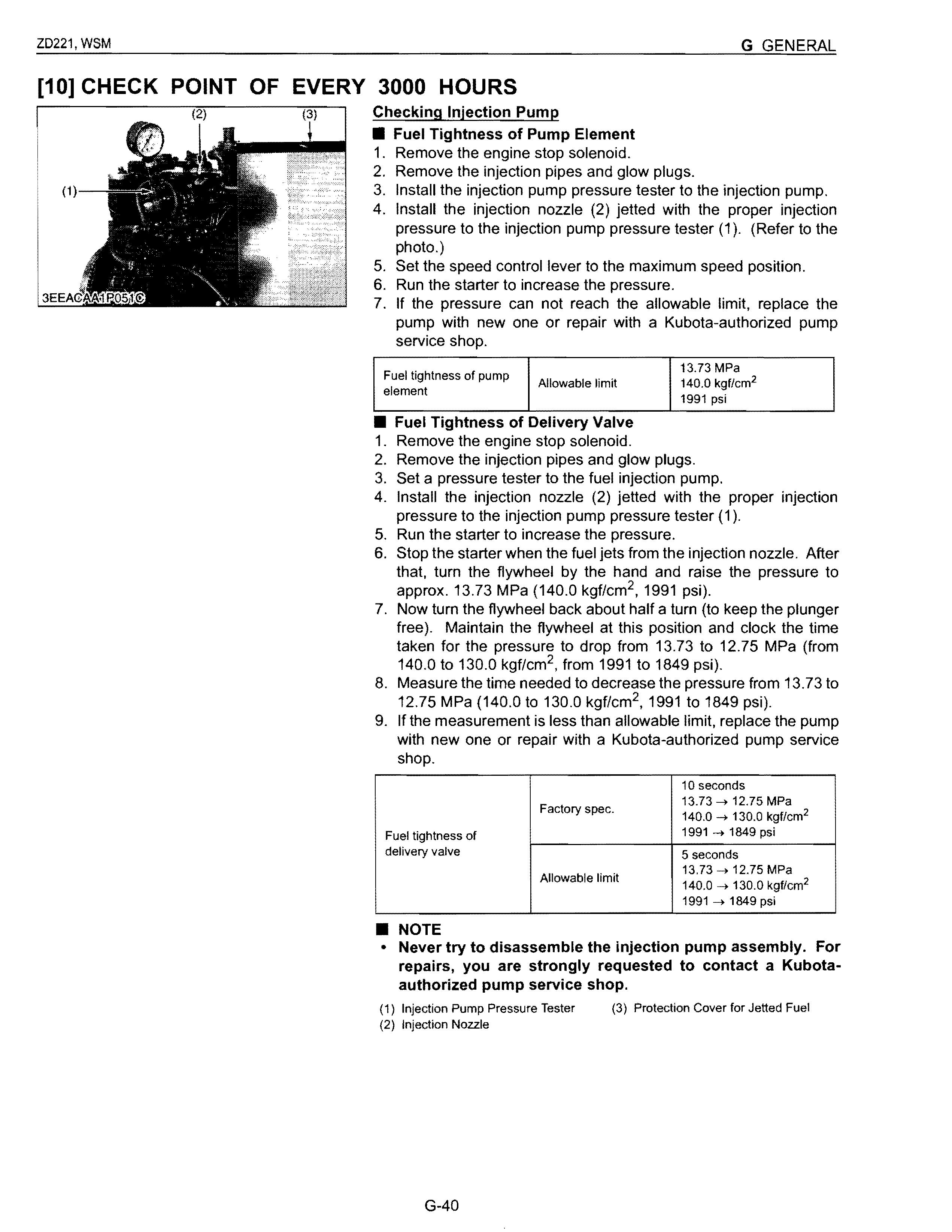
1. Remove the engine stop solenoid.
2. Remove the injection pipes and glow plugs.
3. Set a pressure tester to the fuel injection pump.
4. Install the injection nozzle (2) jetted with the proper injection pressure to the injection pump pressure tester (1).
5. Run the starter to increase the pressure.
6. Stop the starter when the fuel jets from the injection nozzle. After that, turn the flywheel by the hand and raise the pressure to approx. 13.73 MPa (140.0 kgf/cm 2 , 1991 psi).
7. Now turn the flywheel back about half a turn (to keep the plunger free). Maintain the flywheel at this position and clock the time taken for the pressure to drop from 13.73 to 12.75 MPa (from 140.0 to 130.0 kgf/cm 2 , from 1991 to 1849 psi).
8. Measure the time needed to decrease the pressure from 13.73 to 12.75 MPa (140.0 to 130.0 kgf/cm 2 , 1991 to 1849 psi).
9. If the measurement is less than allowable limit, replace the pump with new one or repair with a Kubota-authorized pump service shop.
• NOTE
• Never try to disassemble the injection pump assembly. For repairs, you are strongly requested to contact a Kubotaauthorized pump service shop.
(1) Injection Pump Pressure Tester
(2) Injection Nozzle
(3) Protection Cover for Jetted Fuel
[11] CHECK POINTS OF EVERY 1 YEAR
Replacing Air Cleaner Primary Element and Secondary Element
1. Replace the air cleaner primary element (2) and the air cleaner secondary element (1) with a KUBOTA genuine element.
2. While turning the air cleaner secondary element (1) slightly, pull it out.
• IMPORTANT
• The air cleaner uses a dry element, never apply oil.
• Do not run the engine with filter element removed.
• Be sure to refit the air cleaner cover (1) as shown in the figure. If the air cleaner cover (1) is improperly fitted, evacuator valve (4) will not function and dust will adhere to the element.
• If it is loose, dust and dirt may be sucked in, wearing down the cylinder and piston rings earlier and thereby resulting in poor power output.
• To prevent serious damage to the engine, use only a KUBOTA genuine filter element.
(1) Secondary (Safety) Element
(2) Primary Element
(3) Cover
(4) Evacuator Valve
P: Pull out
T: Turn
W1037268
Flushing Cooling System and Changing Coolant
Acaution
• Do not remove the radiator cap when the engine is hot. Then loosen cap slightly to the stop to relieve any excess pressure before removing cap completely.
1. Stop the engine and let cool down.
2. To drain the coolant, open the radiator drain cock (4) and remove the radiator drain plug (3) and remove the radiator cap (1). The radiator cap (1) must be removed to completely drain the coolant.
3. After all coolant is drained, close the drain cock (4) and install the drain plug (3).
4. Fill with clean water and cooling system cleaner.
5. Follow directions of the cleaner instruction.
6. After flushing, fill with clean water and anti-freeze until the coolant level is just below the fill port on the radiator. Install the radiator cap (1) securely.
7. Fill with coolant up to the "FULL" mark on the recovery tank.
8. Start and operate the engine for a few minutes.
9. Stop the engine and let cool. Check coolant level of recovery tank (2) and add coolant if necessary .
• IMPORTANT
• Do not start engine without coolant.
• Use clean, fresh water and anti-freeze to fill the radiator and recovery tank.
• When the anti-freeze is mixed with water, the anti-freeze mixing ratio must be less than 50 %.
• Securely tighten radiator cap. If the cap is loose or improperly fitted, water may leak out and the engine could overheat.
• Refer to "LUBRICANTS, FUEL AND COOLANT". (See page G-7.)
• Anti-Freeze
If coolant freezes, the cylinders and radiator can be damaged. It is necessary, if the ambient temperature falls below 0 °C (32 OF), to remove coolant mix it with anti-freeze and full the radiator with it.
1. There are two types of anti-freeze available; use the permanent type (PT) for this engine.
2. Before adding anti-freeze for the first time, clean the radiator interior by pouring fresh water and draining it a few times.
3. The procedure for mixing of water and anti-freeze differs according to the maker of the anti-freeze and the ambient temperature, basically should be referred to SAE J1034, more specially also to SAE J814c.
4. Mix the anti-freeze with water, and then fill in to the radiator. Vol % Anti- Freezing Point Boiling Point* freeze
* At 101 kPa (760 mmHg) pressure (atmospheric). A higher bOiling point is obtained by using a radiator pressure cap which permits the development of pressure within the cooling system
• NOTE
• The above date represent industry standards that necessitate a minimum glycol content in the concentrates anti-freeze.
• When the coolant level drops due to evaporation, add water only. In case of leakage, add anti-freeze and water in the specified mixing ratio.
• Anti-freeze absorbs moisture. Keep unused anti-freeze in a tightly sealed container.
• Do not use radiator cleaning agents when anti-freeze has been added to the coolant. (Anti-freeze contains an anticorrosive agent, which will react with the radiator cleaning agent forming sludge which will affect the engine parts.)
W1037402
[12] CHECK POINTS OF EVERY 2 YEARS
Replacing Fuel Lines
• IMPORTANT
• This job should not be done in the field, but in a clean place.
1. Place an oil pan under the fuel line (1).
2. Loosen the pipe clamps.
3. Replace the full lines (1) with KUBOTA genuine parts.
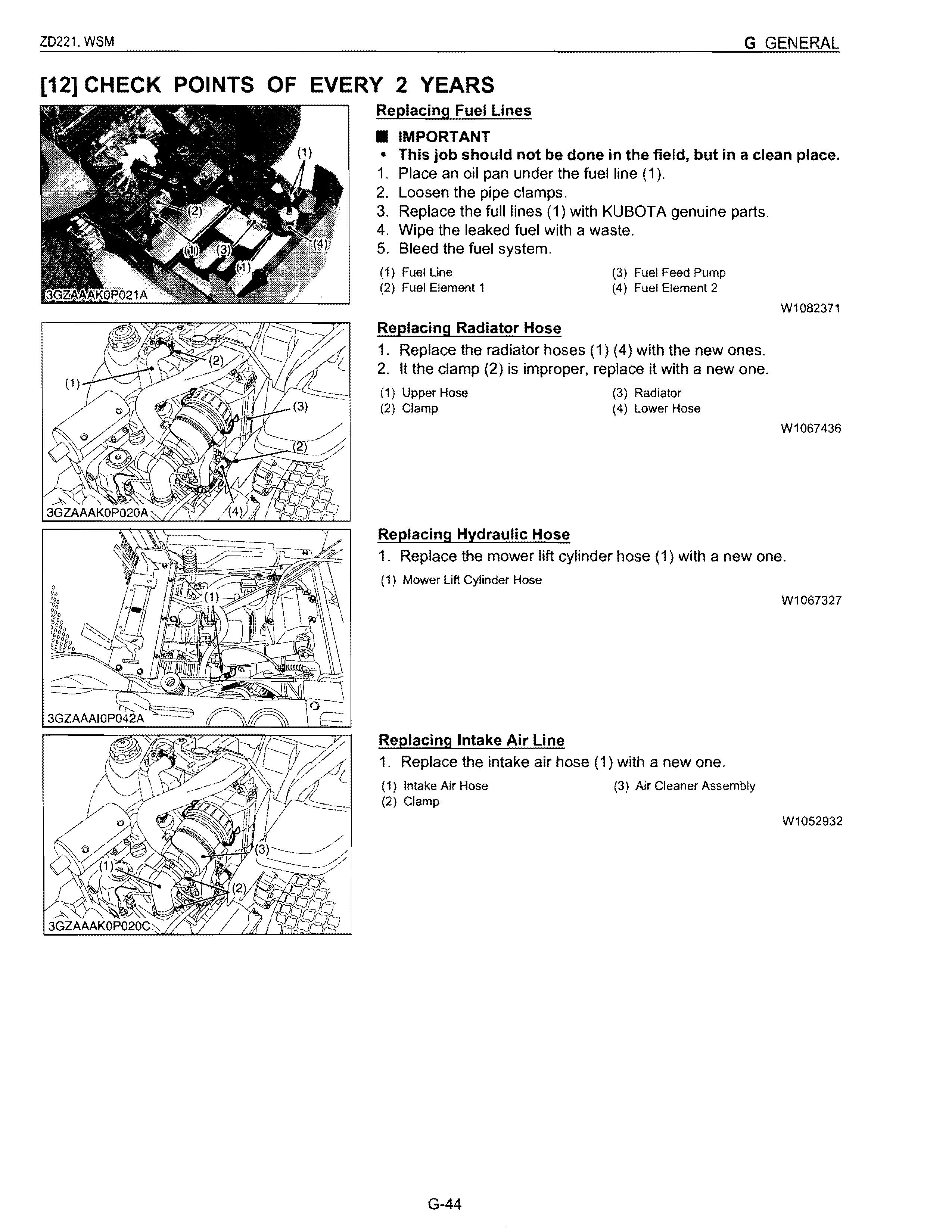
4. Wipe the leaked fuel with a waste.
5. Bleed the fuel system.
(1) Fuel Line
(2) Fuel Element 1
Replacing Radiator Hose
(3) Fuel Feed Pump
(4) Fuel Element 2
1. Replace the radiator hoses (1) (4) with the new ones.
2. It the clamp (2) is improper, replace it with a new one.
(1) Upper Hose
(2) Clamp
(3) Radiator
Lower Hose
W1082371
Replacing Hydraulic Hose
1. Replace the mower lift cylinder hose (1) with a new one.
(1) Mower Lift Cylinder Hose
Replacing Intake Air Line
1. Replace the intake air hose (1) with a new one. (1) Intake Air Hose
(3) Air Cleaner Assembly
W1067436
W1067327
W1052932
3GZAAAIMP006B
Replacing Mower Gear Box Oil Seals
1. Replace the mower gear box oil seals (1), (3).
(1} Oil Seal (3} Oil Seal
(2} Mower Gear Box
W1038357
Replacing Fuses
Replacement of the fuse
1. Raise the operator's seat.
2. Remove the blown fuse.
3. Place a new fuse of the same capacity in position
• IMPORTANT
• Never "jump" the fuse with wire or foil or install a larger capacity fuse than is recommended.
• Protected Circuit FUSE NO. CAPACITY Protected circuit (lD LABEL) (A) 20A Engine stop 15A Charge system 15A Main system
1 15A Aux. outlet 10A Control system (20A) '(Work light)
2 Slow blow fuse 50 A Check circuit against wrong battery connection
* Option. The fuse should be In only when the work light IS attached.
(1) Fuse Location
(2) Slow Blow Fuse
W1038470
3GZAAAI0PQ45B
Replacing Mower Blade
Acaution
To avoid personal injury :
• Be sure to stop the engine and remove the key.
• Blade may be sharp. When you handle blades, wear heavy gloves or wrap end of blade with a rag.
• Checking
The blade cutting edges should be kept sharp at all times. Sharpen the cutting engines, if they resemble blade (B). Replace the blades if they appear similar to blade (C).
• Replacing
1. Tilt up the mower deck.
2. Wedge a block of wood between the blade and mower housing or use a box wrench over the pulley nut to prevent the spindle from rotating while removing the blade bolts; loosen the blade bolt and illustrated.
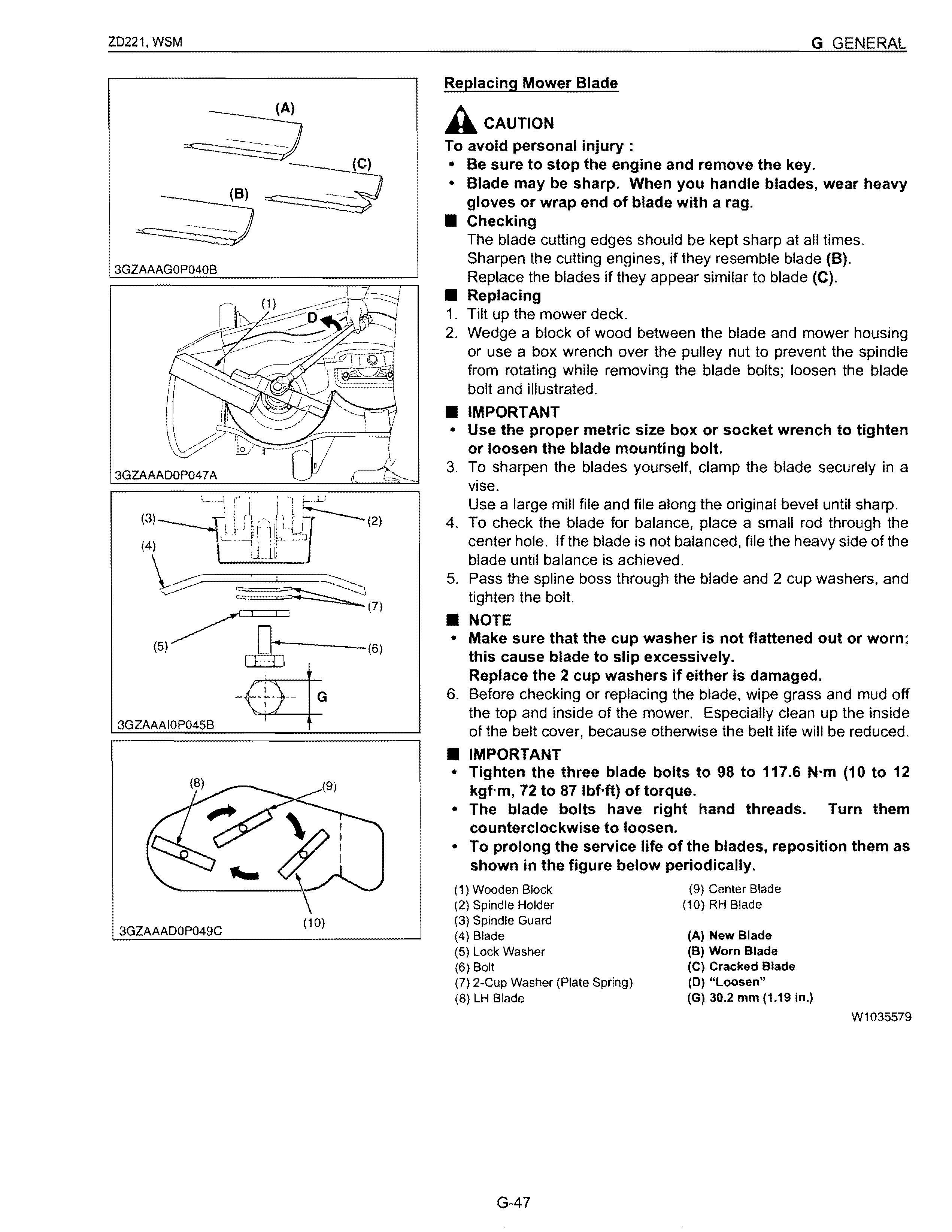
• IMPORTANT
• Use the proper metric size box or socket wrench to tighten or loosen the blade mounting bolt.
3. To sharpen the blades yourself, clamp the blade securely in a vise.
Use a large mill file and file along the original bevel until sharp.
4. To check the blade for balance, place a small rod through the center hole. If the blade is not balanced, file the heavy side of the blade until balance is achieved.
5. Pass the spline boss through the blade and 2 cup washers, and tighten the bolt.
• NOTE
• Make sure that the cup washer is not flattened out or worn; this cause blade to slip excessively. Replace the 2 cup washers if either is damaged.
6. Before checking or replacing the blade, wipe grass and mud off the top and inside of the mower. Especially clean up the inside of the belt cover, because otherwise the belt life will be reduced.
• IMPORTANT
• Tighten the three blade bolts to 98 to 117.6 N'm (10 to 12 kgf'm, 72 to 871bHt) of torque.
• The blade bolts have right hand threads. Turn them counterclockwise to loosen.
• To prolong the service life of the blades, reposition them as shown in the figure below periodically.
3GZAAADOP050C
Replacing Mower Belt
1. Remove the mower deck from the machine according to the procedure "DISMOUNTING THE MOWER DECK".
2. Remove the left and right hand shield from the mower deck.
3. Clean around the gear box.
4. Remove the belt from the tension pulley.
5. Remove the right hand bracket which mounts the gear box to the mower deck and slip the belt over the top of the gear box.
6. To install a new belt, reverse the above procedure.
77.6 to 90.2 N'm
Tightening torque Bracket mounting bolt 8.0 to 9.2 kgf·m
57.1 to 66.51bHt
(1) Tension Pulley
(3) Belt
(2) Bracket (RH) (4) Bracket Mounting Bolt
Bleeding Fuel System
Air must be removed:
1. When the fuel filter or lines are removed.
2. When tank is completely empty.
W1036546
3. After the machine has not been used for a long period of time.
Bleeding procedure is as follows:
1. Fill the fuel tank with fuel.
2. Start the engine and run for about 30 seconds, and then stop the engine. W1069400