Assembly process No.
A-12
Installation of blade (1/9)
Condition1) Before starting the following work, complete "Assembly procedure A-11". 2) Before starting the following work, set the engine so that it can run to move the machine. 1) Posture of blade assembly before installation Fig. 2
Fig. 1
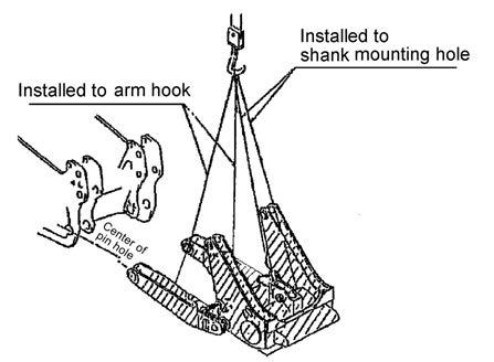
Adjust the posture of the blade assembly before installation with wooden blocks (E) and (F) as shown in (Fig. 1) and (Fig. 2). Dimension a
Dimension b (Disconnect between sphere centers)
About 995 mm
About 3,480 mm
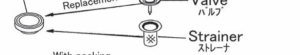
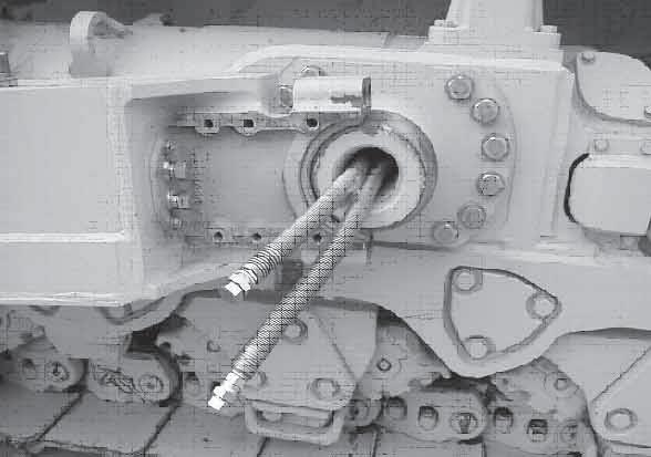
a Dimension a in the table is set on the assumption that the machine is used on a hard ground where the track shoe grousers will not sink. If the machine is used on a ground where the grousers sink, the trunnion height decreases by the sinking distance. Accordingly, dimension a must be lowered by the decrease of the trunnion height. a If the center link falls, dimension b increases. To prevent this, set wooden block (F) under the center link or arm. a Leave wooden block (G) set to erect the blade vertically in “assembly procedure A-11" as it is. 2) Connection of blade assembly and machine Fig. 3 2.1) Peel off the paint from the spherical part of the trunnion and clean its surface. a Apply grease [G2-LI] to the spherical part of the trunnion. G2-LI : See [Coating materials]
Seat
2.2) Set the machine within dimension "b" of the blade assembly and move it forward so that the right and left clearances will be the same. 2.3) Move and press the machine forward until the trunnion is seated in the trunnion holder (bushing) of the blade assembly (straight frame). (Fig. 3)
92