10 minute read
A-12 Installation of blade

Assembly process No.
A-12 Installation of blade (1/9)
Condition1)Before starting the following work, complete "Assembly procedure A-11". 2)Before starting the following work, set the engine so that it can run to move the machine.
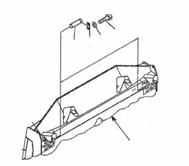
1)Posture of blade assembly before installation
Fig. 1 Fig. 2
Adjust the posture of the blade assembly before installation with wooden blocks (E) and (F) as shown in (Fig. 1) and (Fig. 2).
Dimension a Dimension b (Disconnect between sphere centers) About 995 mm About 3,480 mm
a
a
a Dimension a in the table is set on the assumption that the machine is used on a hard ground where the track shoe grousers will not sink. If the machine is used on a ground where the grousers sink, the trunnion height decreases by the sinking distance. Accordingly, dimension a must be lowered by the decrease of the trunnion height.
If the center link falls, dimension b increases. To prevent this, set wooden block (F) under the center link or arm.
Leave wooden block (G) set to erect the blade vertically in ìassembly procedure A-11" as it is.
2)Connection of blade assembly and machine Fig. 3
2.1)Peel off the paint from the spherical part of the trunnion and clean its surface.
a Apply grease [G2-LI] to the spherical part of the trunnion. Seat
G2-LI : See [Coating materials]
2.2)Set the machine within dimension "b" of the blade assembly and move it forward so that the right and left clearances will be the same.
2.3)Move and press the machine forward until the trunnion is seated in the trunnion holder (bushing) of the blade assembly (straight frame). (Fig. 3)
Assembly process No.
A-12 Installation of blade (2/9)
a If the trunnion and trunnion holder are different in height, trunnion bushing (2) in (Fig. 4) may move when the trunnion is pressed. If the trunnion and trunnion holder are different in height, sling the straight frame of the blade assembly with a crane etc. and adjust their heights.
2.4)Set the trunnion parts (Fig. 4) and tighten the bolts. a Match the chamfered portion of the nut with the round portion.
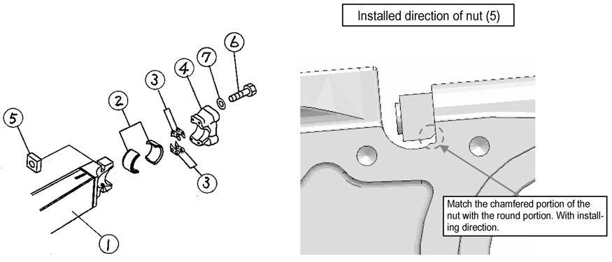
Fig. 4
No. Part name
1 Blade assembly 2 Bushing 3 Plate 4 Cap 5 Nut 6 Bolt 7 Washer Part No.
195-71-74250 195-71-74260 195-71-74231 195-71-11512 207-46-12141 01643-32780 Q'ty for each of right and left Remarks
---- See ìassembly procedure A-13î 2 4 1 4 With installing direction. 4 4
Bolt specification M27, Length : 265 mm
Tool (Socket)
41 mm Tightening torque See Table 1 "Tightening torque"
2.5)Remove wooden block (E) set under the straight frame in step 1).
Assembly process No.
A-12 Installation of blade (3/9)
3)Connection of tiltdozer hydraulic hoses Fig. 5
3.1)Remove the plug at the tip of the hydraulic hose coming out from the center hole of trunnion (refer to item 6.4 of Assembling Procedures A-6).
a Take care not to lose the "O-rings".
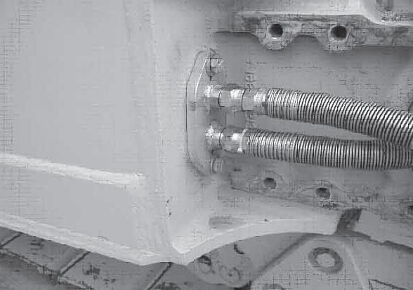
3.2)Remove the upper and lower locknuts from the nipples of the flange (7) in (Fig. 5) on the blade assembly side.
3.3)Connect the hydraulic hoses to the nipples of
a
a When connect, it certainly assembly O-ring (02896-11015) removed in step 3.1).
Connect the hydraulic hoses according to the following table. the above flange. (Fig. 5)
Hose discernment Selection of connecting nipple Blue discernment at hose end Connect to upper nipple.
No discernment on hose Connect to lower nipple. Left side is blue and right side is red.
a The part Nos. of the plug and nut removed from the nipple of the flange in step 2) are shown below for reference.
Dual tiltdozer Single tiltdozerPart name/Part No.
Q'ty Q'ty Nut 07221-20522 2 pieces each on right and left 2 pieces on only right Plug 07376-50522 2 pieces each on right and left 2 pieces on only right
a This part is not necessary any more after the blade assembly is installed to the machine. Keeping this part is recommended, however, since it is necessary again when the blade assembly is removed from the machine and stored.
When the front work equipment is the single tiltdozer, perform this work only on the right side.
Assembly process No.
A-12 Installation of blade (4/9)
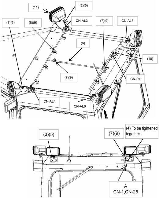
4)Installation of tiltdozer hydraulic hose protection cover
Install tiltdozer hydraulic hose protection cover (8) (Fig. 6) connected in step 3).
Fig. 6
No. Part name 1 Blade assembly 4 Trunnion cap 8 Cover 9 Bolt 10 Washer Part No. Q'ty
195-71-74240 1 each on right and left 01010-62050 6 each on right and left 01643-32060 6 each on right and left Remarks
See 2.4) of this procedure
Bolt specification M20, Length : 50 mm
Tool (Socket)
30 mm Tightening torque See Table 1 "Tightening torque"
a Before installing the protection cover, check the operation of the tilt cylinder in the blade adjustment work described later and confirm that there is not oil leakage or another problem in the tilt hose connection.
Assembly process No.
A-12 Installation of blade (5/9)
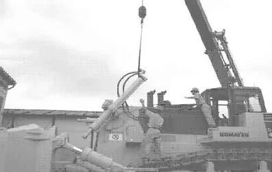
5)Connection of blade assembly and blade lift cylinders
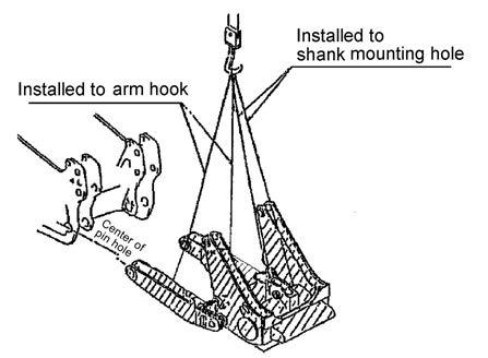
5.1)Sling the hydraulic cylinder with the belt sling and remove the transportation sling bracket. (Fig. 7), (Fig. 8)
Belt sling
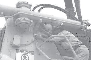
Sling bracket
a
Connect the hydraulic cylinders one by one.
5.2)Check the hydraulic oil level while the shank point is in contact with the ground, and add new hydraulic oil according to the Operation and Maintenance Manual if necessary. (If the hydraulic oil level is low, the work equipment pump may be damaged.)
5.3)Start the engine and operate the blade control lever to extend/retract the hydraulic cylinder rod and align it with the connecting hole (joint link) of the blade assembly. Part (A) in (Fig. 9)
a The work shall be performed by the machine operator, crane operator, and "signalman". The signalman must arrange the signaling method in advance and give proper directions to both operators.
5.4)Insert the connecting pin in part A. (Fig. 9)
5.5)Stop the engine.
5.6)Set the lock to the connecting pin head and bolt it to the joint link. (Fig. 9)
Connecting pin part No. 198-71-61240 (1 piece each on right and left)
Part No. of lock 198-72-62170 (1 piece each on right and left)
Part No. of bolt 01010-81635 (2 pieces each on right and left)
Part No. of washer 01643-31645 (2 pieces each on right and left)
Bolt specification M16 35 mm Socket 24 mm
Tightening torque See Table 1 "Tightening torque"
5.7)Install blade cylinder holdfast (11) on the upper side of the cylinder to fix the cylinder. Fig. 7
Fig. 8
Fig. 9
Fig. 10
Assembly process No.
A-12 Installation of blade (6/9)
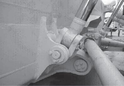
6)Connection of blade assembly and blade tilt hydraulic cylinder
6.1)Remove the pins from the right and left of the cylinder connecting side (blade). (Fig. 11)
a For the single tiltdozer, remove the pin from only the right side. For the left side, see ìassembly procedure A-11î Installation of brace assembly.
No. Part name Part No. Q'ty
12 Pin 195-71-61590
13 Lock 195-71-51450
14 Bolt 01010-62050 1 peace each side 1 peace each side 2 peaces each side
15 Washer 01643-32060 2 peaces each side
Bolt specification M20, Length : 50 mm
Tool (Socket) 30 mm
6.2)The bottom side (clevis side) of the hydraulic cylinder has been connected to the straight frame already. See ìassembly procedure A-11" Raise one end of this hydraulic cylinder with the belt sling and remove the wooden block placed under it. (Fig. 12)
6.3)With the hydraulic cylinder raised, start the engine and operate the blade control lever to extend/retract the hydraulic cylinder rod and align its pin hole (P) with the pine hole (Q) of the blade. (Fig. 12)
a The work shall be performed by the machine operator, crane operator, and "signalman". The signalman must arrange the signaling method in advance and give proper directions to both operators. Fig. 11
Fig. 12
Assembly process No.
A-12 Installation of blade (7/9)
6.4)After aligning the pin holes, stop the engine and insert pin (12) removed in step 6.1) and fix it to the blade with lock (13), bolt (14) and washer (15). (Fig. 13)
a
a Perform the work from step 6.2) to step 6.4) on the right and left sides. However, perform on only the right side for the single tiltdozer.
For the tightening torque of bolt (14), see "Tightening torque", Table 1 in this manual. Fig. 13
6.5)Loosen and remove the slings of the hydraulic cylinder.
6.6)Start the engine again and operate the blade control lever to raise the whole blade assembly. Then, remove all the wooden blocks placed under the blade.
6.7)Lower the blade to the ground and stop the engine.
7)Confirmation of operation of blade assembly
7.1)Check of hydraulic oil level and supply of new oil
[1]Check the hydraulic oil level again and supply new oil, if necessary.
a
a
a Confirm the oil level after lowering the ripper shank and blade to the ground and set the back of the blade perpendicular to the ground.
About the kind of used fluids refer to ìAssembly procedure A-20î Check on the amount of lubricants and coolant.
If the hydraulic oil level is low, the work equipment pump may be damaged.
7.2)Check of each part for interference
[1]Move the blade slowly and check that each part does not make interference or abnormal sound.
If abnormal sounds seem to come from the ball joints at both ends of the center brace, see step 7.5).
[2]Confirm that the blade does not interfere with the machine (radiator guard) when it is tilted to the maximum (or dual-tilted to the maximum for the dual tiltdozer) at the maximum lifting height.
[3]Confirm that there is sufficient clearances between the straight frames of the blade assembly and the tracks of the undercarriage when the blade is tilted to the maximum (or dual-tilted to the maximum for the dual tiltdozer).
Assembly process No.
A-12 Installation of blade (8/9)
7.3)Confirmation of operation of single tiltdozer [1]Confirm that the blade is "raised" and "lowered" according to the operation of the blade control lever. (Fig. 14) [2]Confirm that the blade is "right-tilted" and "left-tilted" according to the operation of the blade control lever. (Fig. 15) [3]Inspect according to the "Field assembly inspection check sheet" attached to the end of this manual. a If the lateral balance or the clearance between blade assembly and machine needs to be adjusted and the brace assembly length must be adjusted consequently as a result of the check, return to ìassembly procedure A-11î Assembly of blade, 6. Installation of brace assembly, and readjust those items. The above items can be adjusted with the adjustment handle attached to the brace, the direction of the handrail may change. Accordingly, do not apply this method. If brace (63) is rotated with lever (73) to adjust dimension L, the direction of handle (70) changes. According, do not apply this method.
7.4)Confirmation of operation of dual tiltdozer [1]In addition to [1] and [2] of the single tiltdozer specification, ensure that the blade is "pitched back" and "pitched forward" according to the operation of the blade control lever. (Fig. 16) [2]Furthermore, confirm that the blade is "leftdual-tilted" and "right-dual-tilted" according to the operation of the blade control lever. [3]Inspect according to the "Field assembly inspection check sheet" attached to the end of this manual. Raise
Lower Fig. 14
Fig. 15
Right tilt
Left tilt
Reverse pitch
Forward pitch Fig. 16
7.5)Readjustment of ball joint shims at both ends of center brace
When the blade is tilted to the right or left, if abnormal sound comes from either of the ball joints at both ends of the center brace, remove the ball cap of the ball joint which produces the abnormal sound and add the thinnest shim (0.5 mm) according to ìassembly procedure A-11î Assembly of blade, step 4, and tilt the blade again to check.
Assembly process No.
A-12 Installation of blade (9/9)
7.6)Bleeding air Bleed air from the hydraulic circuit according to the following procedure. 1)Run the engine at low idle 2)Extend and retract the cylinders to above 100 mm before each stroke end 4 ñ 5 times. (Do not relieve the pressure at each stroke end.) 3)Extend and retract the cylinders to each stroke end 3 ñ 4 times. 4)While the shank point is on the ground, check that the hydraulic oil level is normal. If the hydraulic oil level is lower than the specified level, add hydraulic oil according to the Operation and Maintenance Manual. a Lower the blade to the ground, too, at this time. 5)When bleeding air, check that each cylinder hose moves freely and oil does not leak through any joint a If the hydraulic oil level is low, the work equipment pump may be damaged. Accordingly, bleed air carefully and check the hydraulic oil level, and then add hydraulic oil if necessary.