2 minute read
A-3 Installation of pivot shaft


Assembly process No.
A-3 Installation of pivot shaft (1/2)
Note) This work is required for disassembly to 32-t parts for transportation.
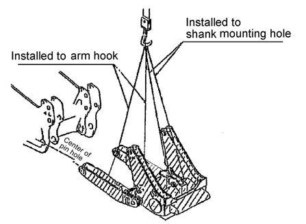
1)Slinging pivot shaft ï To sling the pivot shaft, install the sling as shown in (Fig. 1). ï A proper length of the sling wire is about 600 mm. Dimension (A) in (Fig. 1) ï Install the sling wire to about 500 mm from the pivot shaft end. Dimension (B) in (Fig. 1) Part Nos. of pivot shafts Right shaft Left shaft
Dual 195-50-42111 195-50-42111
Single 195-50-42111 195-50-42210
2)Setting position of pivot shaft * For details of installation, see the following page. ï Set the pivot shaft to the machine with its flange directed as shown in (Fig. 2). 3)Bolting to machine ï When installing the pivot shaft, tighten the bolts lightly and evenly in the diagonal order to press fit the spigot joint portion until the flange face is seated. ï Use an impact wrench (ñ 306 kgm) and a socket shown in the following table. (See [Fig. 3]) ï While turning the torsion seal cover properly, tighten the bolts.
Note: After tightening, be sure to check the tightening torque.
Part No. of bolt 01010-83000 (14 pieces each on right and left) Part No. of washer 01643-33080 (14 pieces each on right and left) Bolt specification M30 100 mm Socket 46 mm Tightening torque 1,720 ± 196 Nm (175 ± 20 kgm) Fig. 1
Fig. 2


Fig. 3
Tilt hose
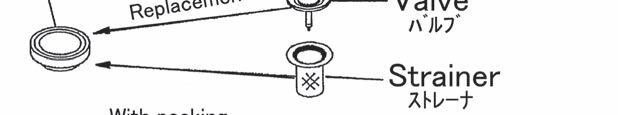
4)Installation of cork plug
After tightening the above bolts, drive the cork plugs into the screw bolt holes in which the bolts of the pivot shaft flange will not be installed.
Part name Part No. Qíty
Plug 07049-03038 2 pieces each on right and left
Assembly process No.
A-3 Installation of pivot shaft (2/2)
Remarks1.Torsion seal (2) is press fitted to the large diameter end of pivot shaft (1) in advance. In addition, torsion seal retainer (3) is fitted in a free rotation state to bring the torsion seal in close contact with the track frame that will be described later. (Fig. 4) Fig. 4
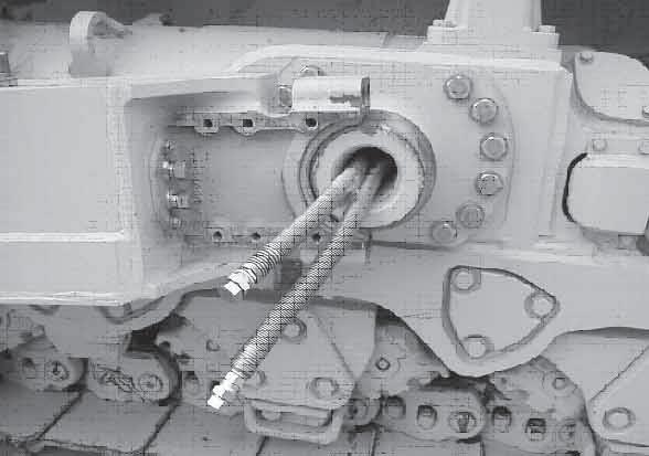
2.There are 2 tilt hoses (4) and (5) for work equipment hydraulic system coming out of the pivot shaft mounting seat of the machine.
Pass both of these tilt hoses through the center hole of the pivot shaft so that they will come out of the shaft end.
At this time, do not twist the tilt hoses spirally inside the pivot shaft hole and set the one having identification color mark up. (Fig. 4) (1)Pivot shaft (2)Torsion seal (3)Torsion seal retainer (4)Tilt hose
Set one having identification color mark on neck up. (5)Tilt hose
Set one having no identification color mark on neck down.
3.The pivot shaft may have been installed to the machine before delivery.
4.This assembly work shall be performed on the right and left sides of the machine. The tilt hose piping on both sides are different from each other as shown below.
Machine specification
Dual tiltdozer
Single tiltdozer Installing position in machine Tilt hose type
Left Upper 1 hose having identification blue mark Lower 1 hose having no identification color mark
Right
Upper 1 hose having identification red mark Lower 1 hose having no identification color mark Left Without tilt hose
Right Upper 1 hose having identification red mark Lower 1 hose having no identification color mark