Assembly process No.
Installation of ripper (1/7)
A-9 1. Installation of beam and arm assembly
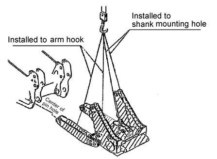
a The following is the installation procedure for the giant ripper. The installation procedure for the multi-shank ripper is basically the same as the following. a Remove all the rust-preventive oil from the ripper mounting pin and then coat the pin with new grease. a Before starting the following work, remove the lift cylinders and tilt cylinder which have been installed for transportation. Lift cylinder ass’y (1 piece) : 270 kg Tilt cylinder ass’y (1 piece) : 260 kg 1) Sling the front part with 2 chain blocks (2 t) so that slant to the right or left can be adjusted. Weight of beam and arm : Approx. 4.2 t (Multi-shank ripper specification)
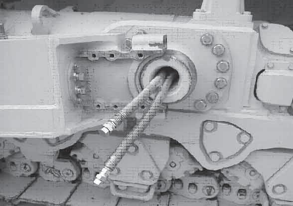
2) Since the pins at the mount are heavy, do not remove them from the mount but leave both of them inside when installing the arm. a Insert a bar between the pins and insert the pins halfway Precautions
Necessary tools Name 2-t chain block ø20 mm × 2 m Wire rope sling ø20 mm × 3 m Wire rope sling Nylon sling for 2t
Other remarks
67
Q'ty 2 2 1 2
Necessary equipment Name Q'ty