Assembly process No.
Installation of additional cab lights (if equipped) (1/2)
A-15 For machine without camera
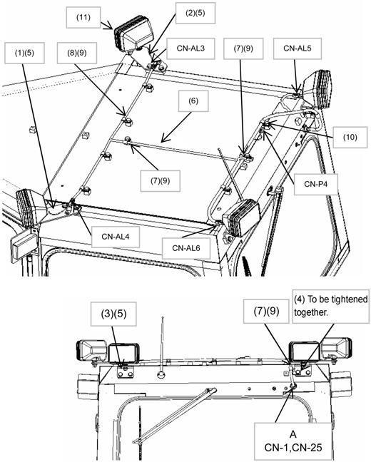
1. Installation of additional lights to cab top (1) Install brackets (1), (2), (3), and (4) to the top and rear of the cab by using bolts (5). (2) Install wiring (6) by using clamps (7), (8), and bolts (9). (3) Remove the cap at the rear of the cab, take out the internal wiring connectors (No. CN-1, 25) through the hole, connect them, and return them into the cab. Put wiring grommet (A) to the hole. (4) Tighten clip (10) together with the clamp to fix the connector (CN-P4). (5) Install lamps (11) to the brackets and connect the connectors (CNAL3, AL4, AL5 and AL6). * Adjust the light angles as necessary.
No.
Part No.
Q'ty
1
Bracket
Part name
198-Z11-7830
1
For left
Remarks
2
Bracket
198-Z11-7840
1
For right
3
Bracket
198-Z11-5490
2
For rear
4
Bracket
207-92-51270
1
For right rear
5
Sems bolt
01024-D1225
8
6
Wiring harness
195-Z11-7350
1
7
Clamp
04434-51412
7
8
Clamp
04434-51012
4
9
Sems bolt
01024-81220
9
10
Clip
08193-21012
1
11
Work lamp
17A-06-17931
4
Halogen
Work lamp
21T-06-33980
4
HID
123