JLG 34HA Parts Manual (3120804) PDF Download En

Page 256

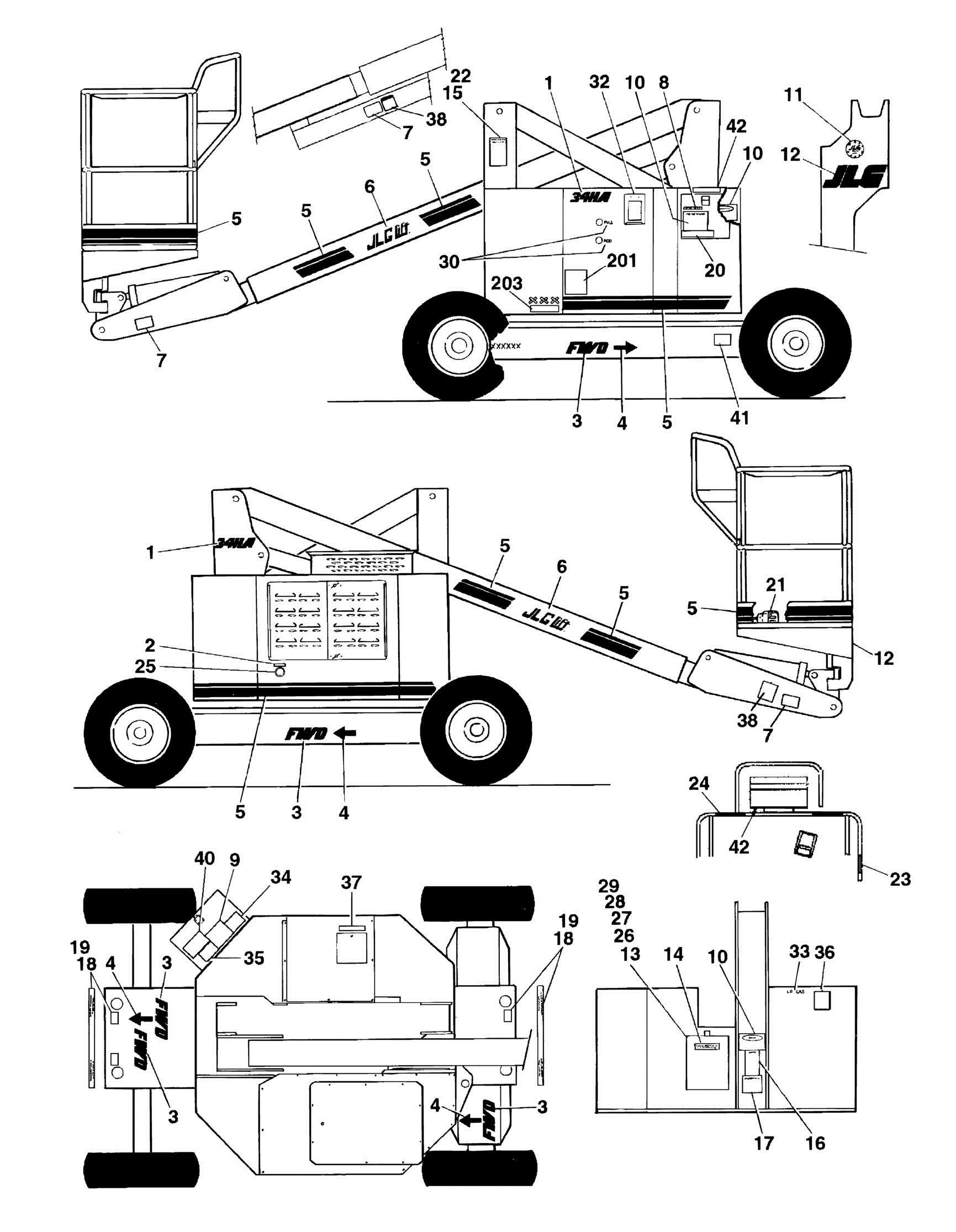
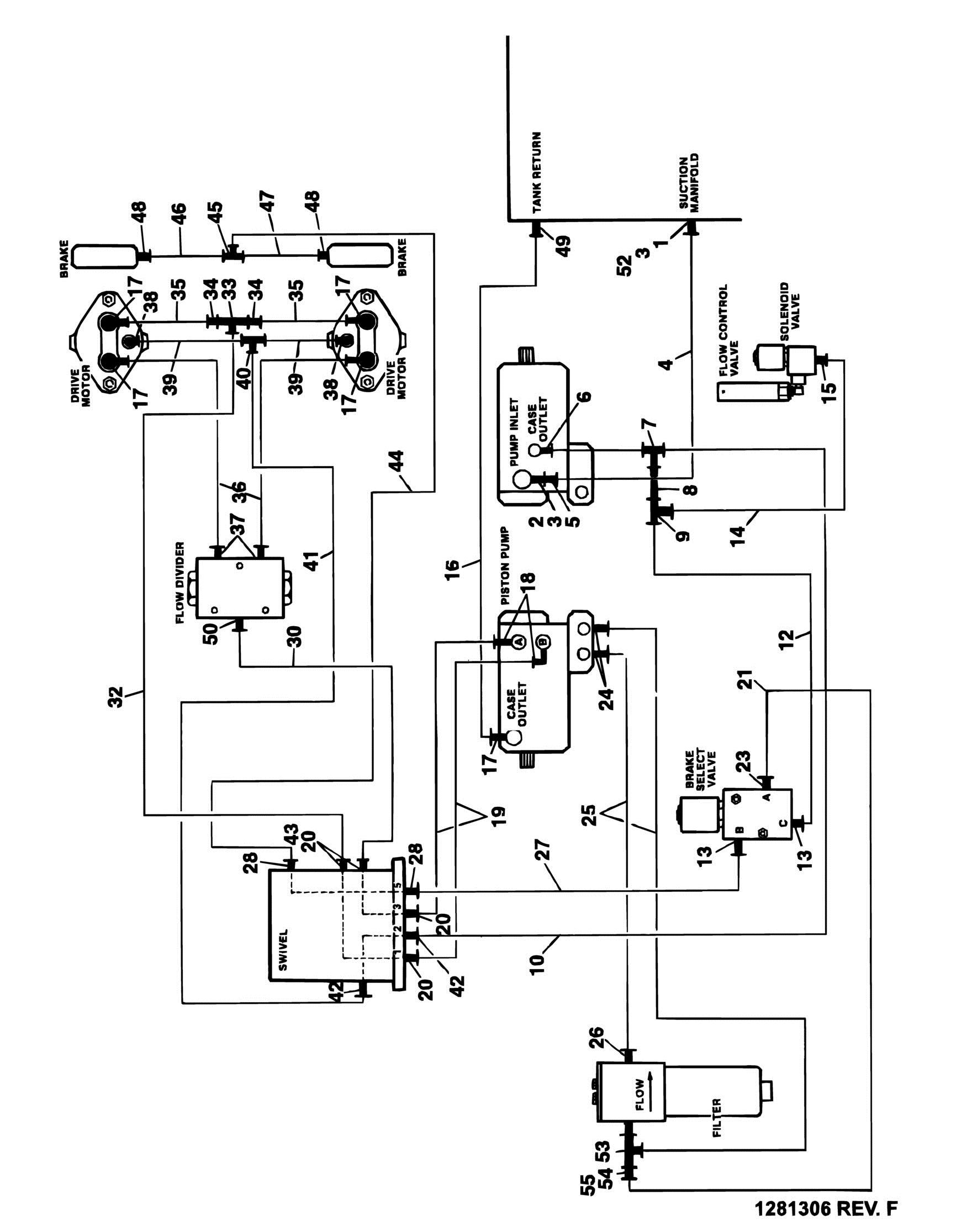
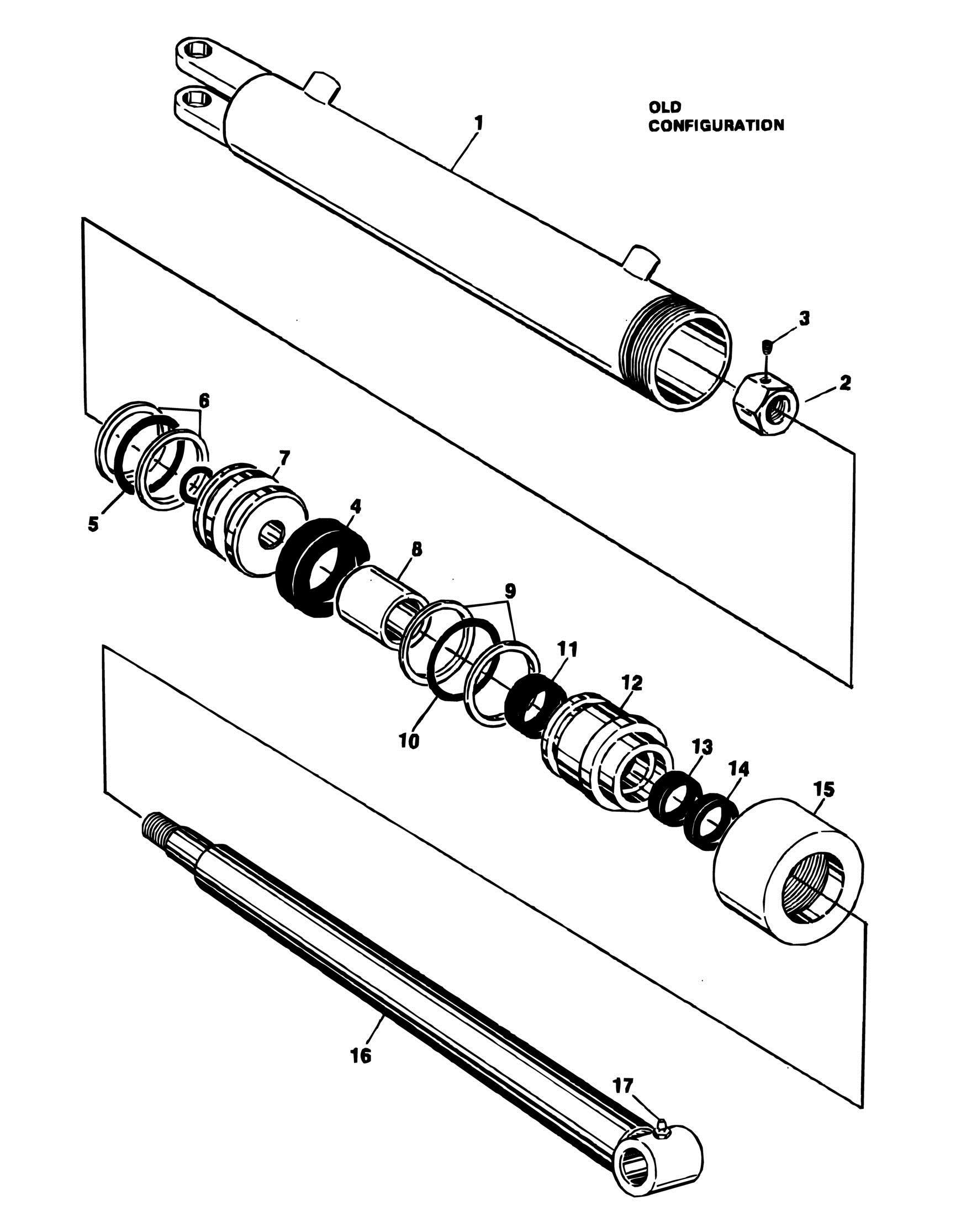
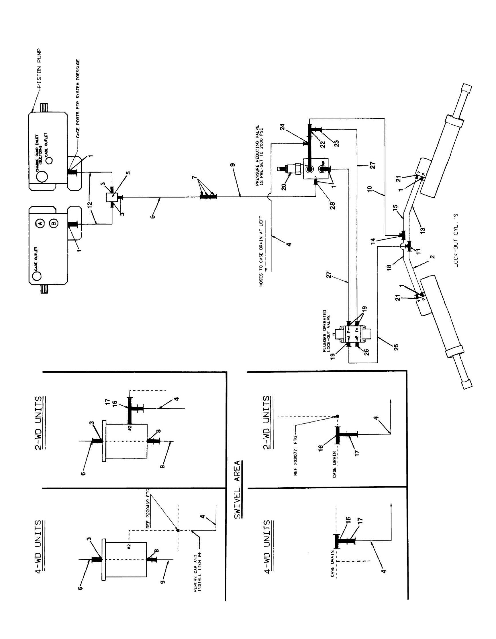
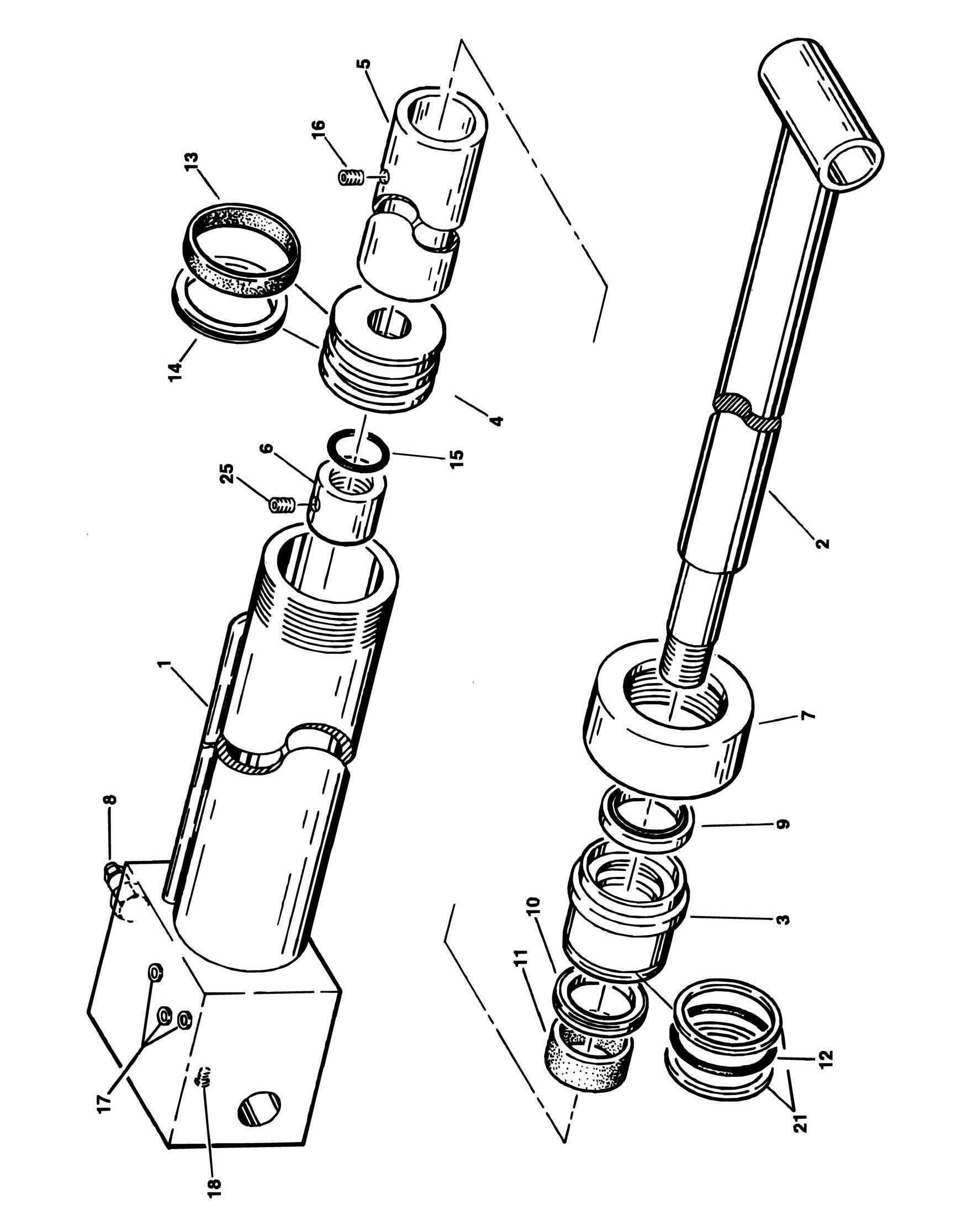
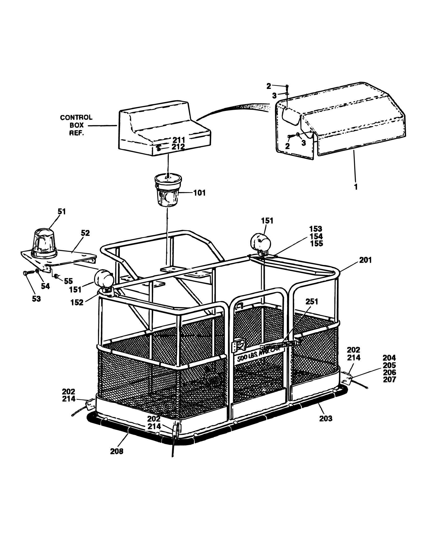
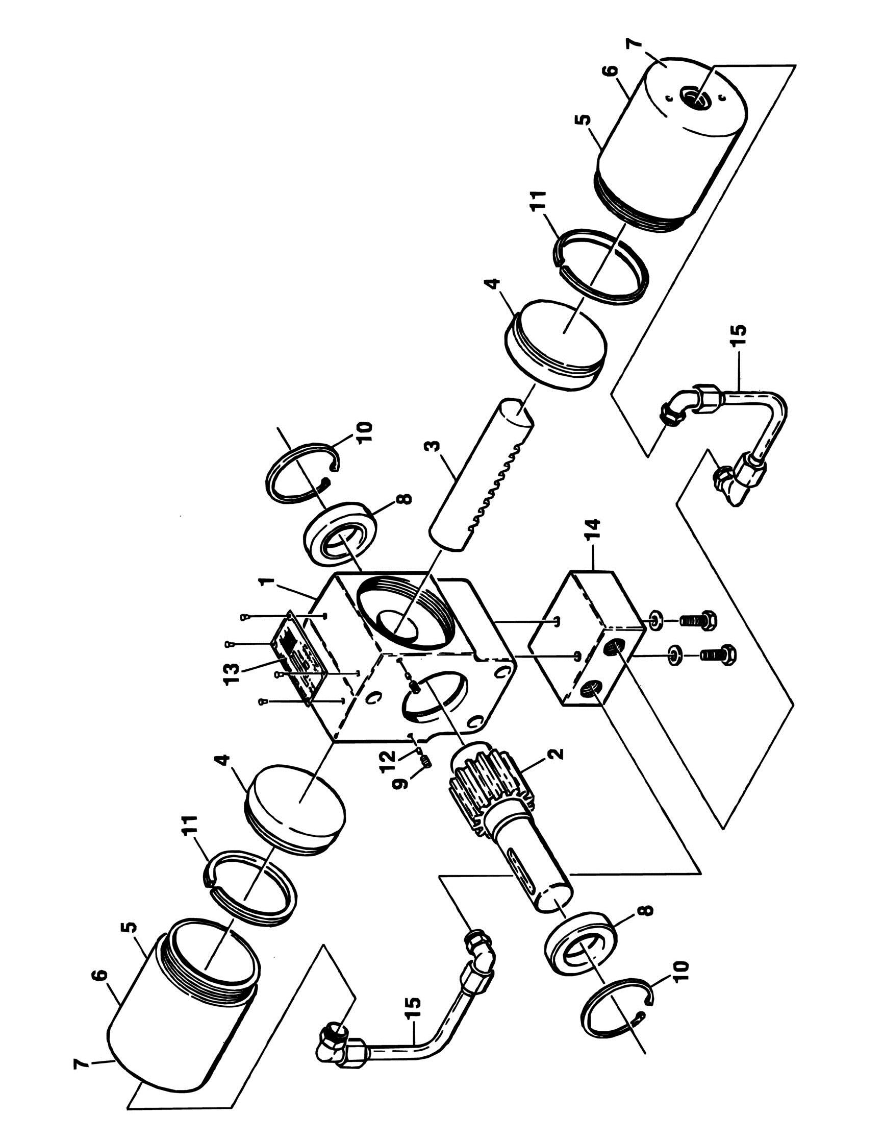
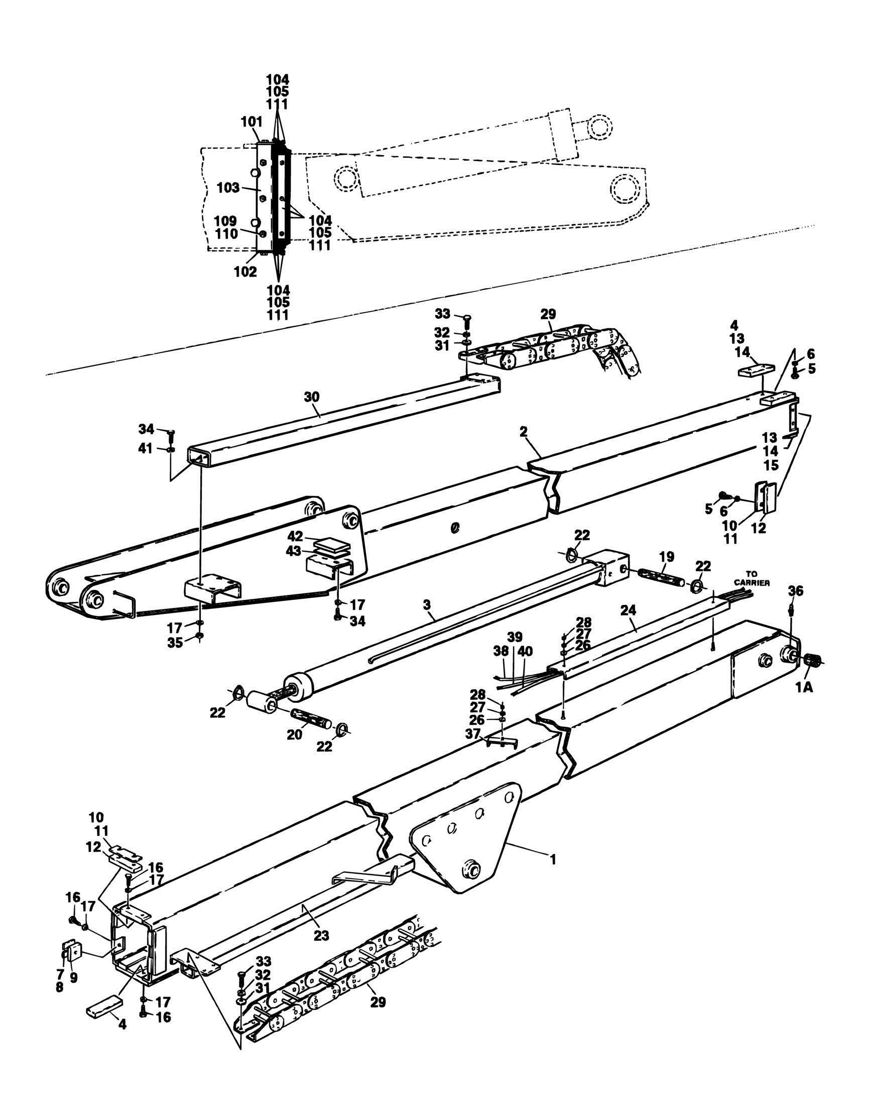
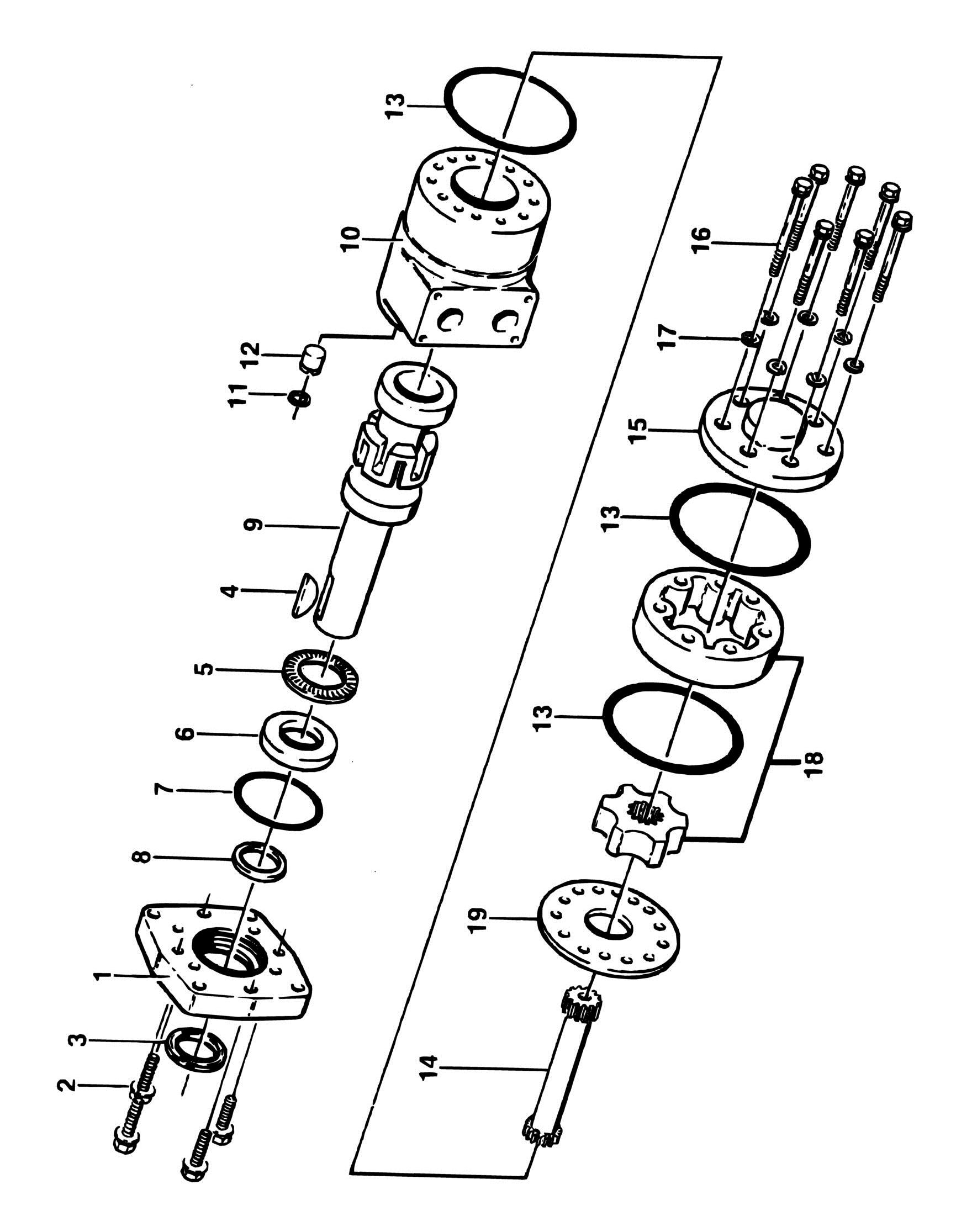
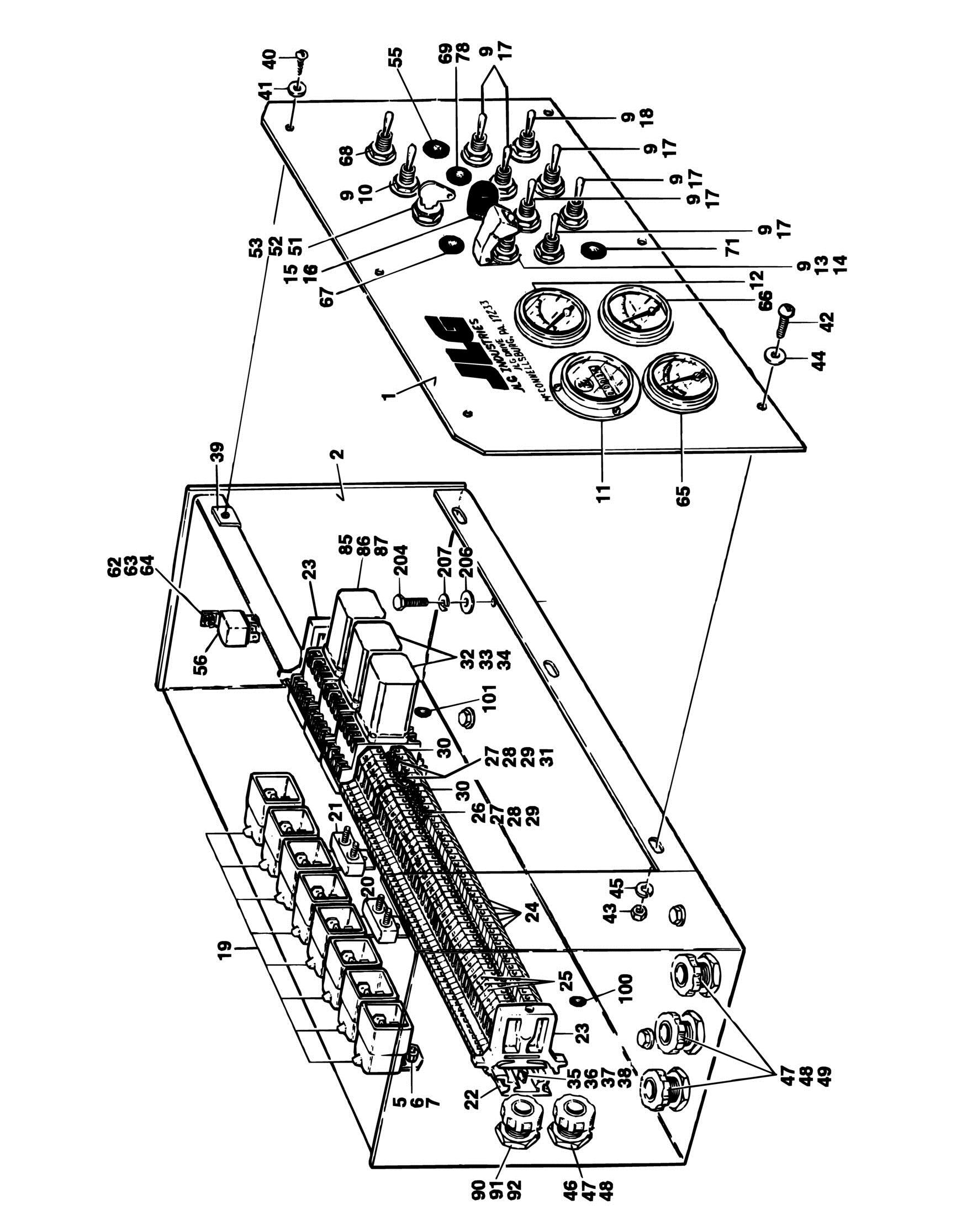
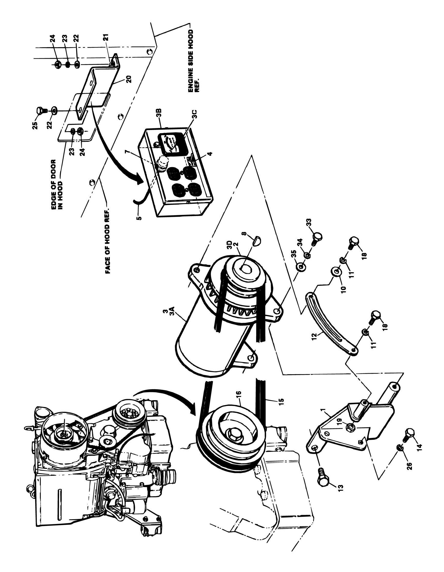
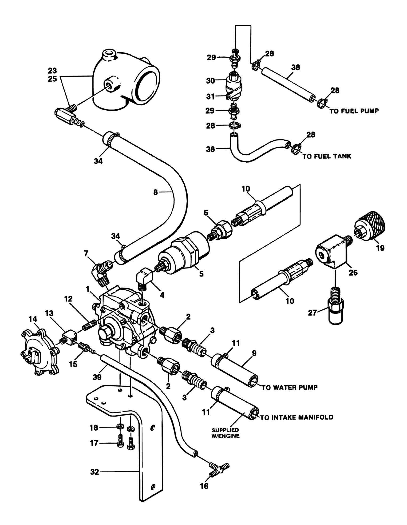
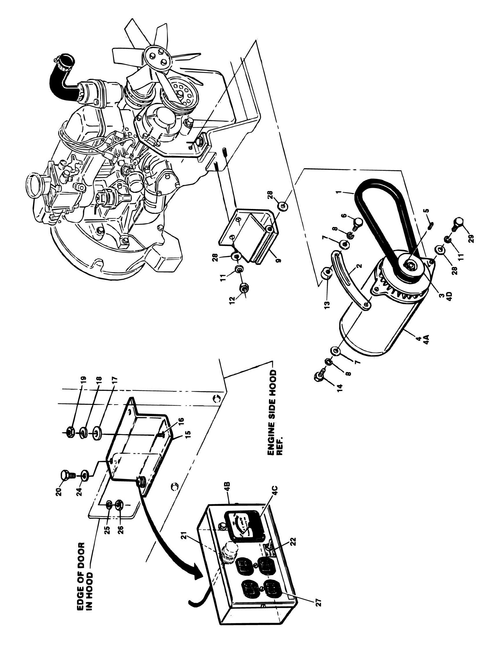
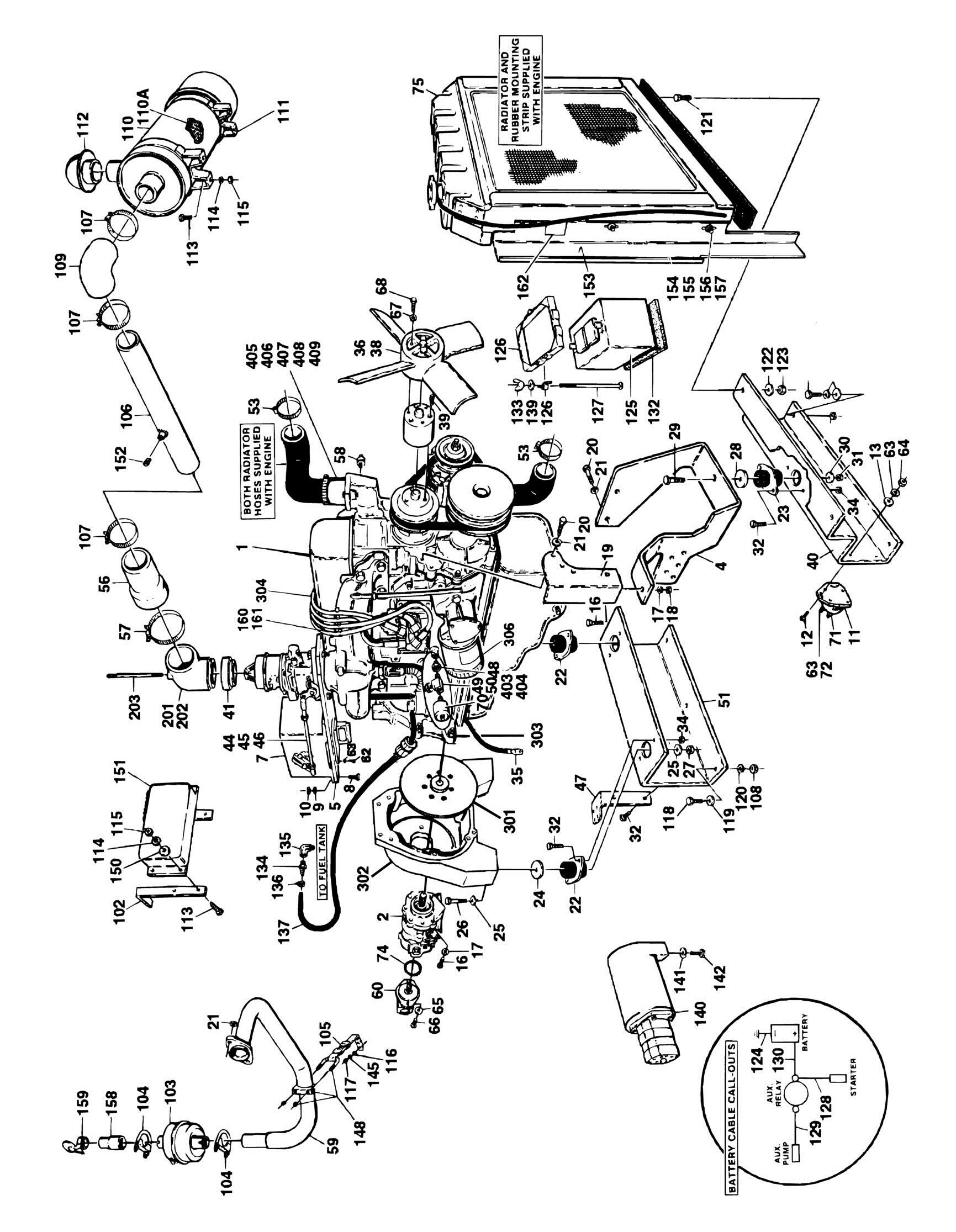
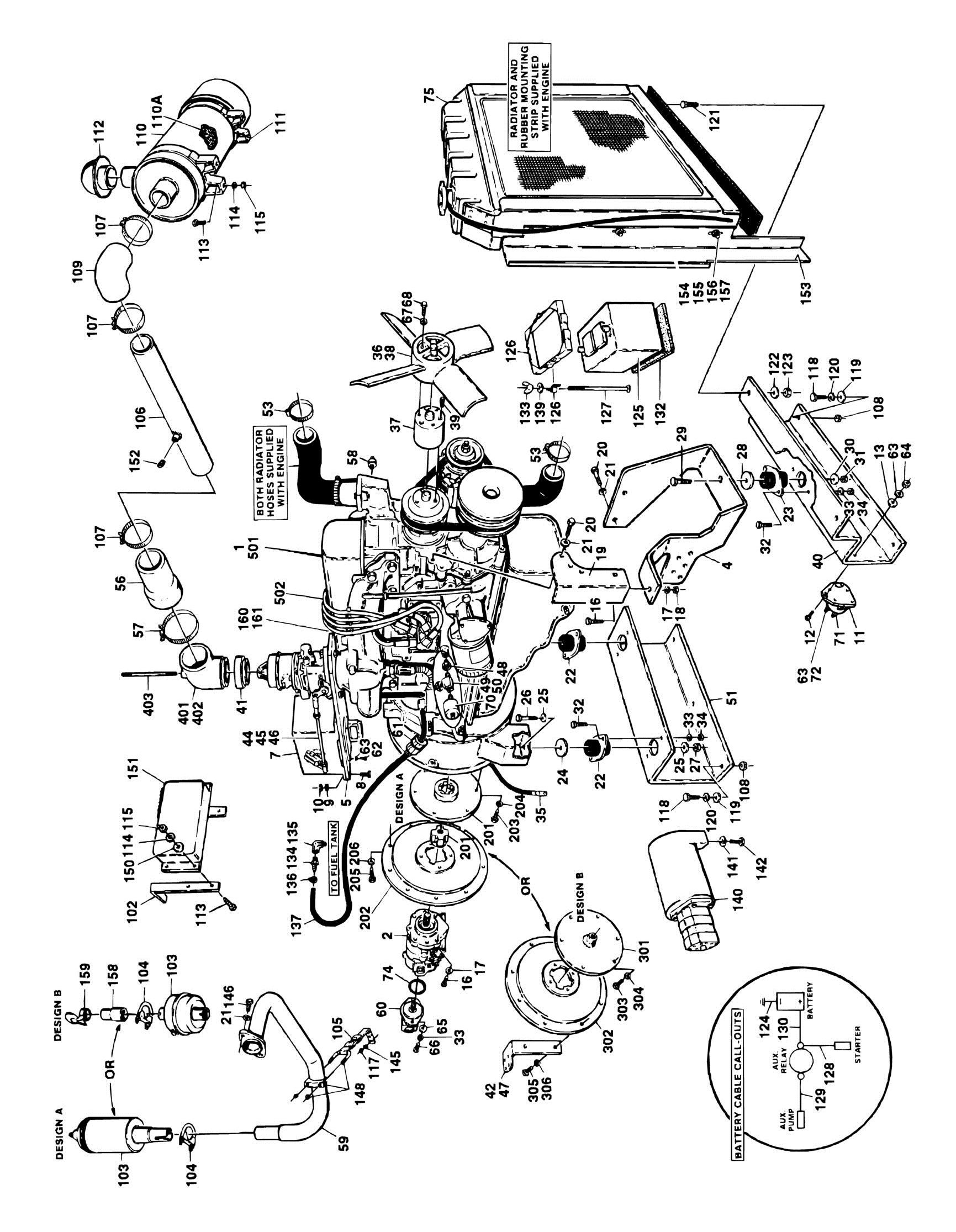
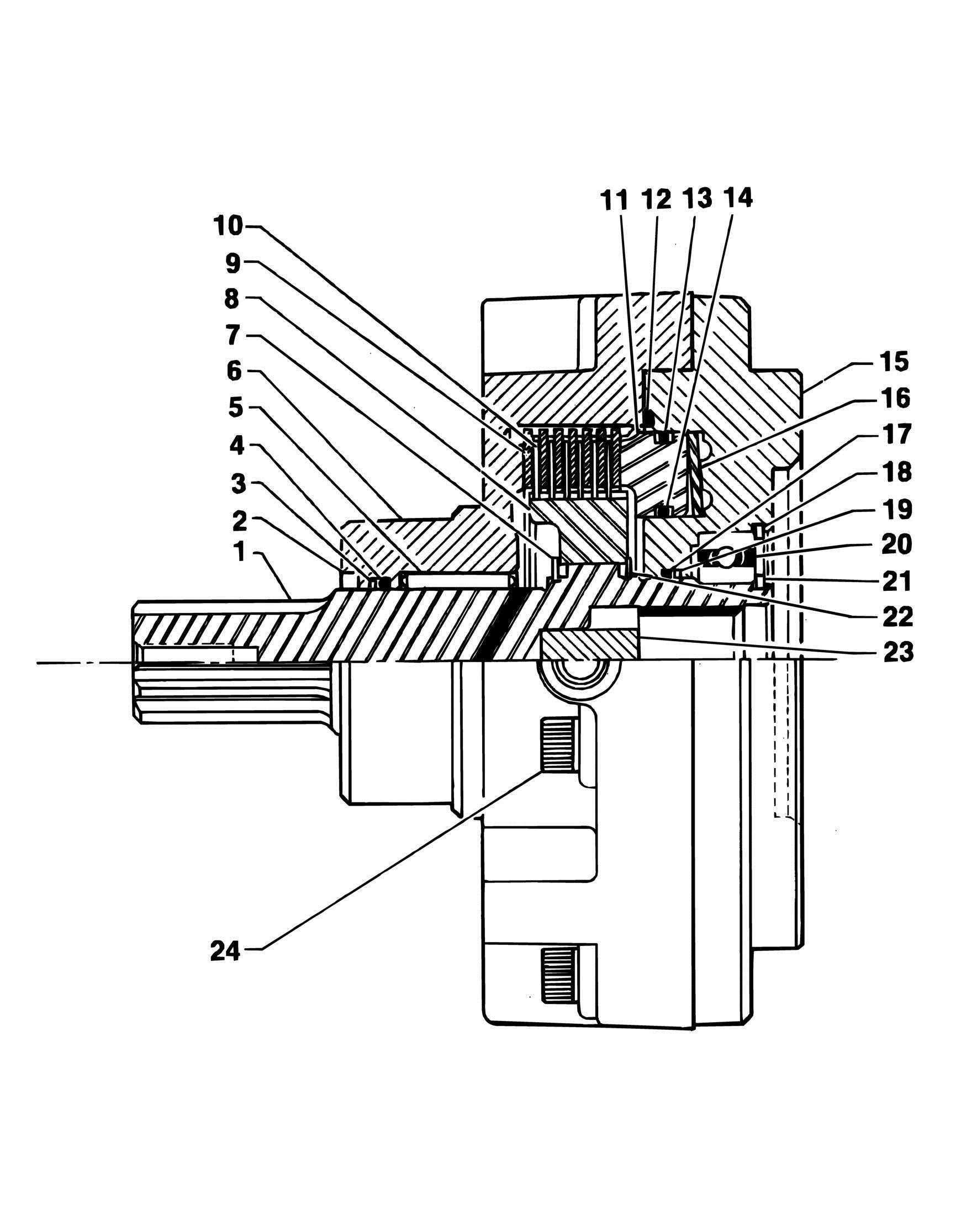
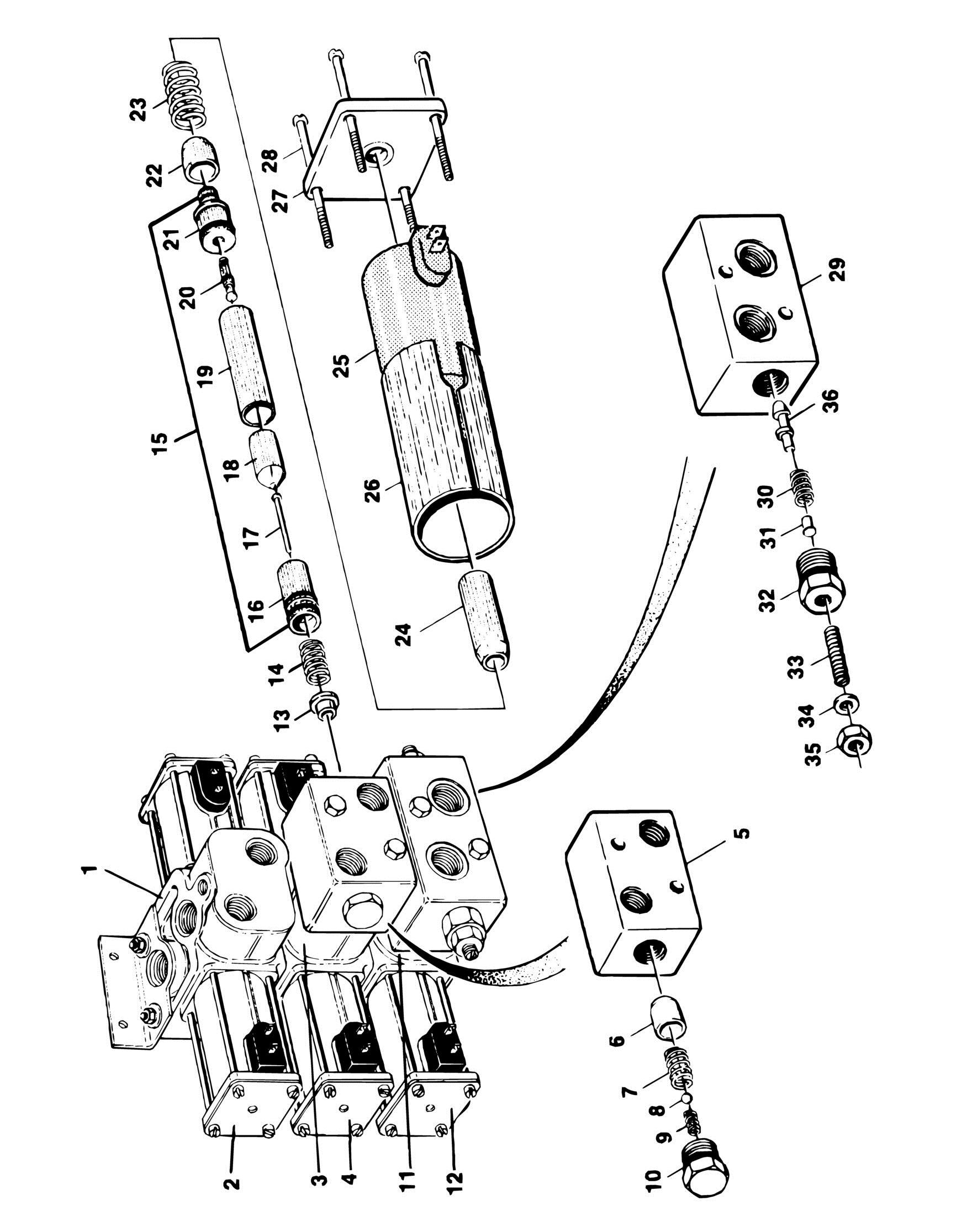
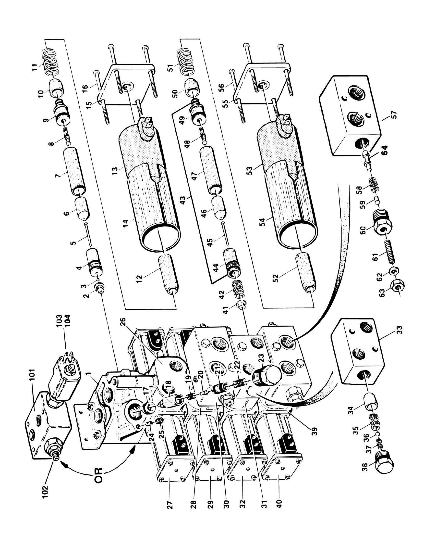
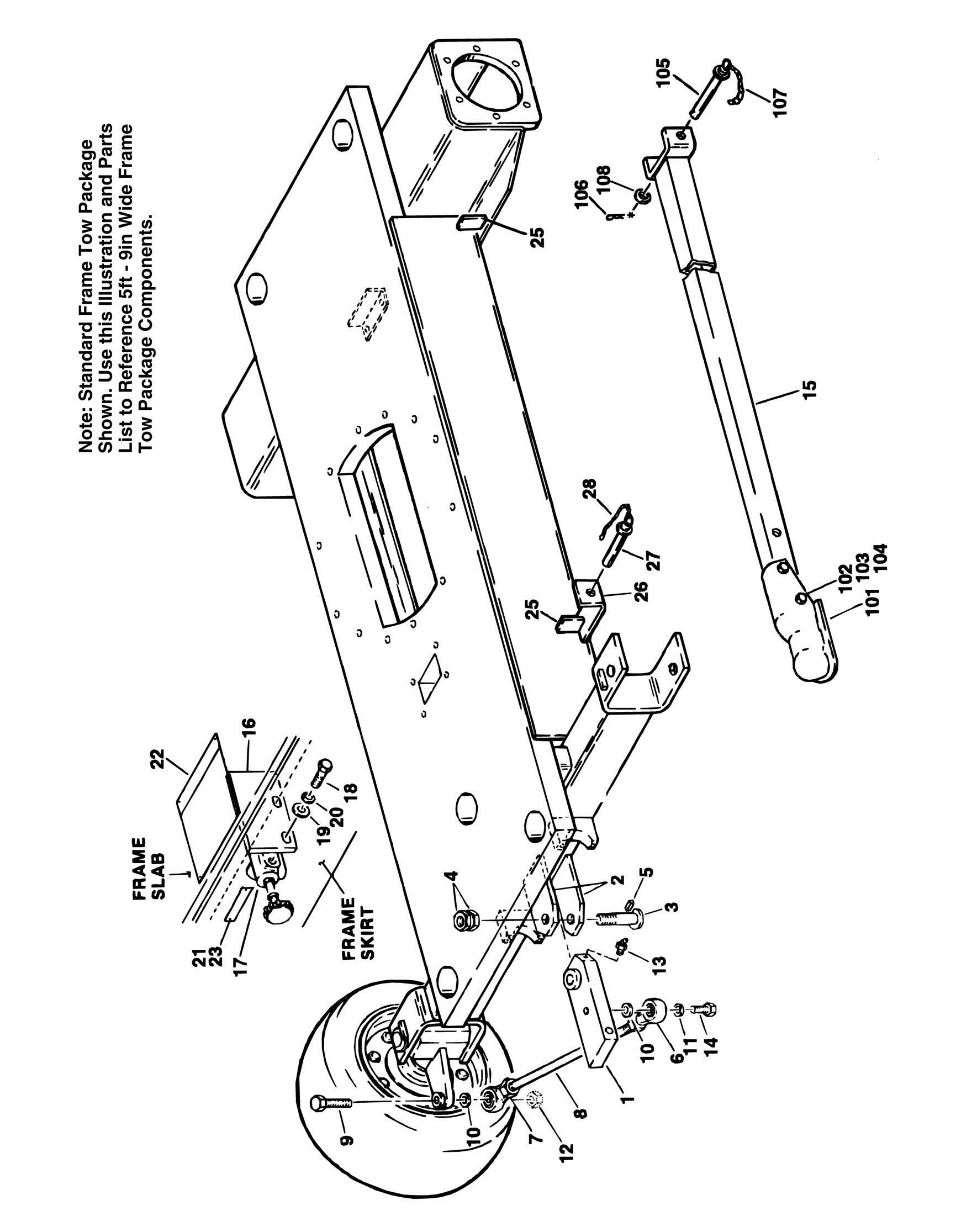
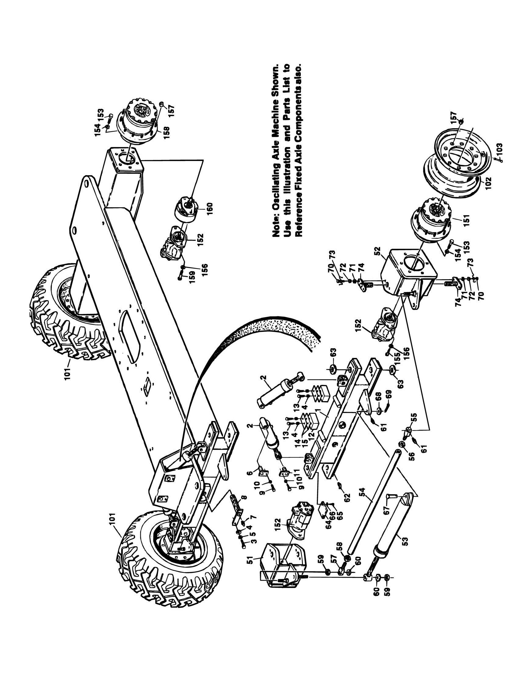
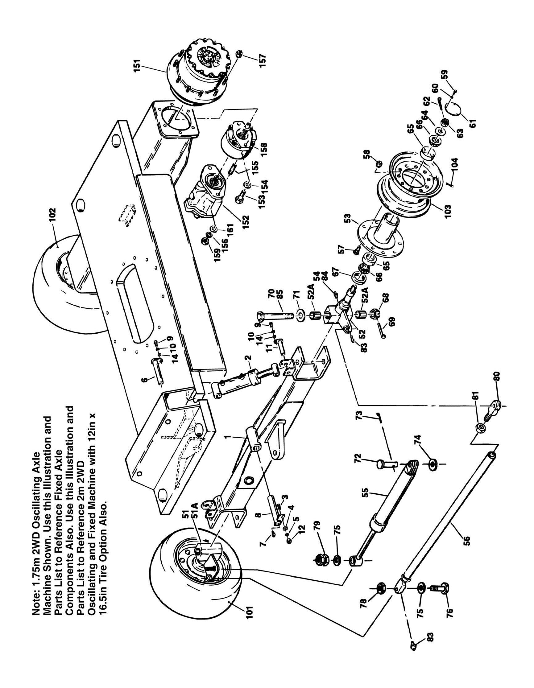
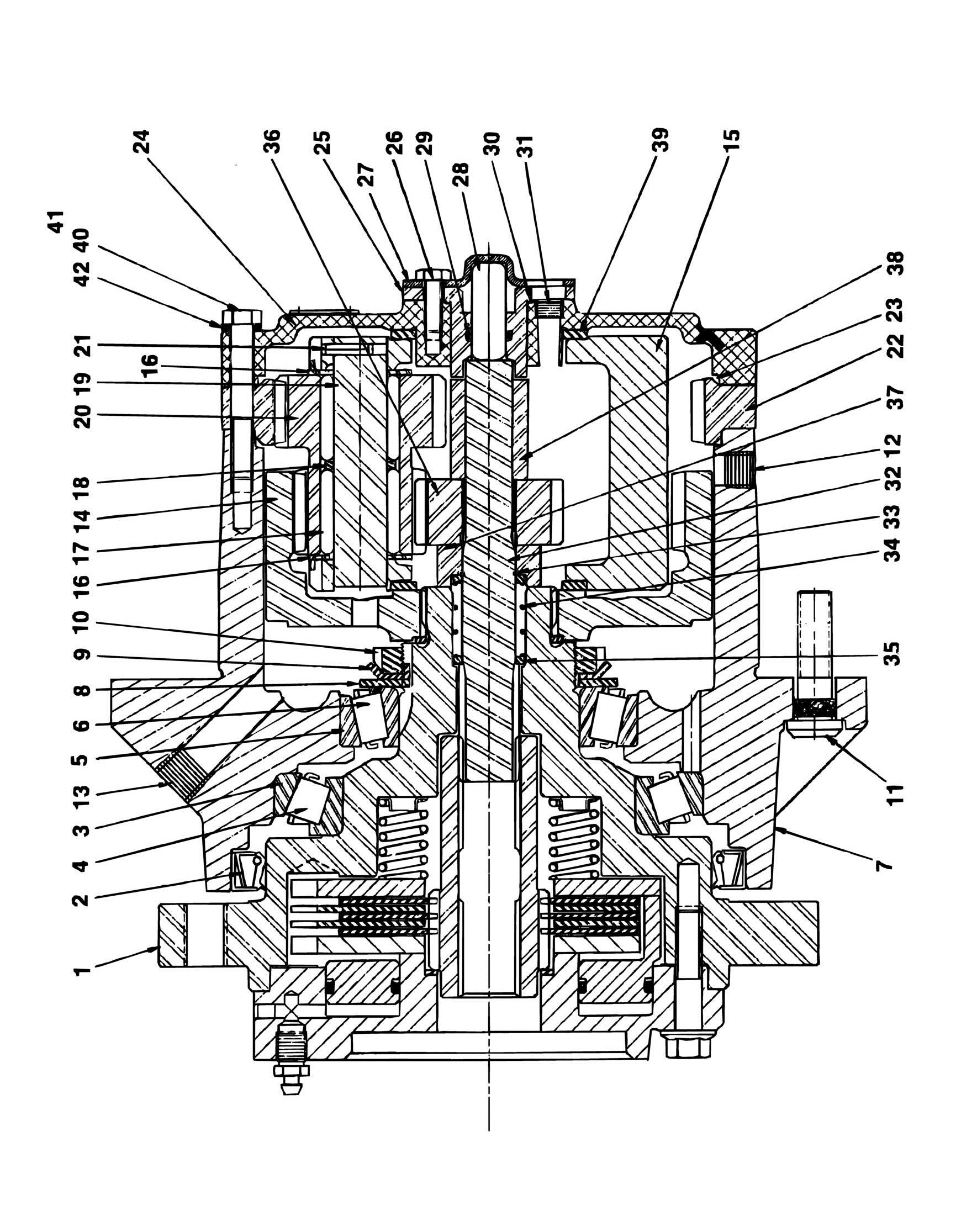
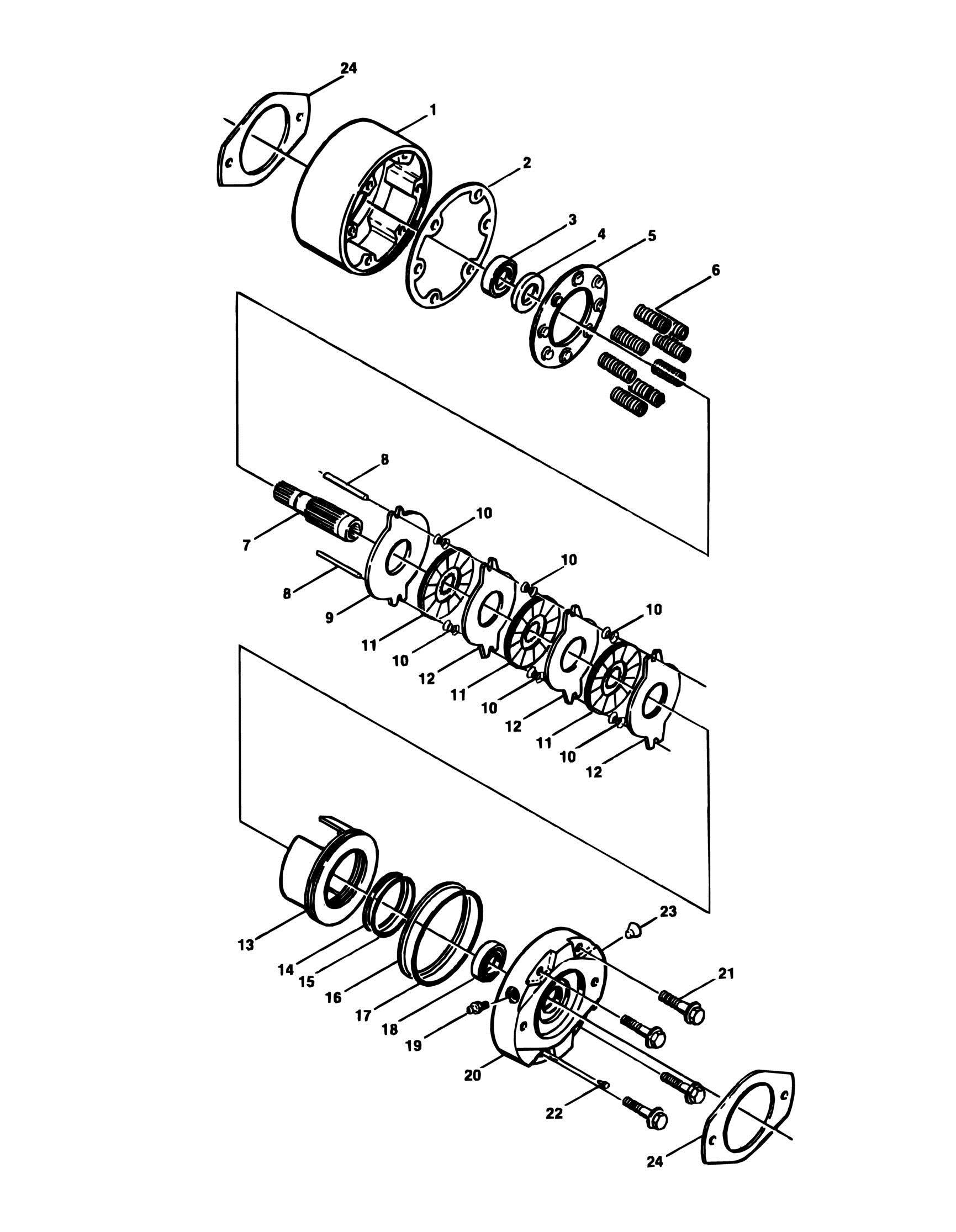
SECTION 10 - SPECIAL OPTIONS FIGURE 10-1. SPECIAL OPTIONS

ITEM

PART NUMBER Note

0238682 9983463 0251273 0251649 0251475 0253234 0251975 2420075 0251939 2420049 0253802 0252263 0252259 0252260 0252261 0252262 0253269 1001148902 1001148903 1001148904 1001148905 1001148906

2910438 1001110986 1001109675 1001110133 0251692 0251619 0253987 0270723 0251180 4360263 0253558 0251921 0256829 9900493 0257728 0256436 0258918

256

QTY Ref

Ref Ref Ref Ref Ref Ref Ref Ref Ref 1 Ref 1 Ref Ref Ref Ref Ref Ref Ref Ref Ref Ref Ref Ref Ref Ref Ref 1 1 1 1 Ref Ref Ref Ref Ref 1 Ref Ref Ref Ref Ref Ref Ref

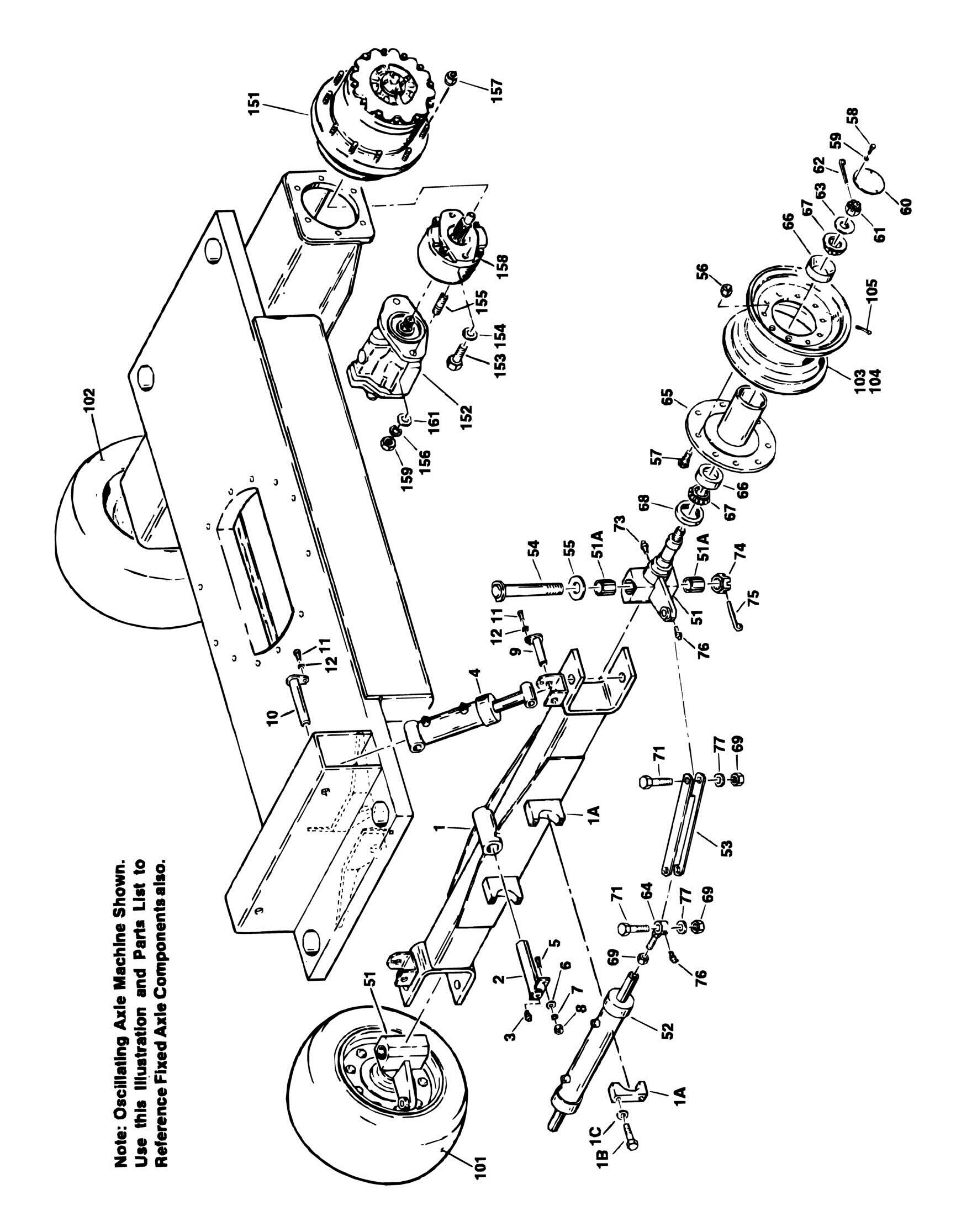
DESCRIPTION Note: This list is to accomodate machines ordered with special equipment. Options may not be applicable to all models. For more specific parts information contact JLG Parts Department. MISCELLANEOUS SPECIAL OPTIONS Airline to Platform Installation Airline Sketch at Platform Axle Conversions 4WD Oscillating to Fixed 2WD With 6ft 6in Frame Oscillating to Fixed 2WD With 12 x 16.5 Tires Oscillating to Fixed 2WD With 5ft 9in Frame Oscillating to Fixed Installation Battery Gauge - Electric Machines Gauge Installation Battery Meter Gauge - Electric Machines Gauge Country Spec Installations Australian Spec Dutch Spec English Spec French Spec German Spec Italian Spec Spanish Spec Electrical Connector Kit - Amp/Tyco Electrical Connectors Electrical Connector Kit - Deutsch DT Electrical Connectors Electrical Connector Kit - Deutsch HD Electrical Connectors Electrical Connector Kit - Packard Electrical Connectors Electrical Connector Kit - Various Electrical Connectors Filter Kits: Combined Filter Kit (Hydraulic/Air and Fuel/Engine Oil) (Deutz Engine): Prior to August 1995 August 1995 to Present Hydraulic/Air Filter (Deutz Engine) Fuel/Engine Oil Filter (Deutz Engine) Inverter 110Volt Generator (Electric Machines) Panel Lights Installation - Standard With Creep Platform Lights Installation - Ford and Deutz Beacon, Amber Platform Interlock Installation (French Spec) Limit Switch Receptacle Plate Installation (Australian Spec) Safe Load Indicator System Installation (French Spec) Spring Loaded Platform Gate Installation Tool Kit Tube Rack (180Lbs Capacity) Installation Tube Rack Installation Utility Rack Assembly

34HA

REV

1

3120804


Turn static files into dynamic content formats.

Create a flipbook

Articles inside

FIGURE 9 1. MODEL 34HA STANDARD PARTS

5min
pages 248-251

FIGURE 8 1. DECALS INSTALLATION STANDARD (PRIOR TO JULY 1991

4min
pages 238-241

FIGURE 10 1. SPECIAL OPTIONS

1min
page 256

FIGURE 7 1. ELECTRICAL DIAGRAM LIST

6min
pages 218-221

FIGURE 6 8. HYDRAULIC DIAGRAM STANDARD (ELECTRIC

2min
pages 204-207

FIGURE 6 10. HYDRAULIC DIAGRAM TOW

1min
pages 210-211

FIGURE 6 11. HYDRAULIC DIAGRAM LIFT UP RELIEF (FORD AND DEUTZ

1min
pages 212-213

FIGURE 6 9. HYDRAULIC DIAGRAM STEER

1min
pages 208-209

FIGURE 6 7. HYDRAULIC DIAGRAM STANDARD (FORD DEUTZ

2min
pages 200-203

FIGURE 6 6. HYDRAULIC DIAGRAM ROTATOR (WORM GEAR

1min
pages 198-199

FIGURE 6 5. HYDRAULIC DIAGRAM ROTATOR (HYDRAULIC PISTON

1min
pages 196-197

FIGURE 6 4. HYDRAULIC DIAGRAM DRIVE (ELECTRIC

1min
pages 194-195

FIGURE 6 3. HYDRAULIC DIAGRAM DRIVE (4WD

1min
pages 190-193

FIGURE 5 3. LIFT (BOOM) CYLINDER ASSEMBLY

1min
pages 166-167

FIGURE 5 7. STEER CYLINDER ASSEMBLY 4WD

1min
pages 174-175

FIGURE 5 9. CYLINDER BELLOWS INSTALLATIONS

1min
pages 178-180

FIGURE 6 2. HYDRAULIC DIAGRAM DRIVE (2WD

2min
pages 186-189

FIGURE 5 6. STEER CYLINDER ASSEMBLY 2WD SINGLE ROD

1min
pages 172-173

FIGURE 6 1. HYDRAULIC DIAGRAM AXLE LOCKOUT

1min
pages 182-185

FIGURE 5 8. TELESCOPE CYLINDER ASSEMBLY

1min
pages 176-177

FIGURE 4 7. OPTIONAL COMMON PLATFORM MOUNTED COMPONENTS

1min
pages 158-160

FIGURE 5 1. AXLE LOCKOUT CYLINDER ASSEMBLY

1min
pages 162-163

FIGURE 4 6. PLATFORM CONSOLE BOX ASSEMBLY (PROPORTIONAL CONTROLS

2min
pages 154-157

FIGURE 4 5. PLATFORM CONSOLE BOX ASSEMBLY

2min
pages 150-153

FIGURE 4 4. ROTATOR MOTOR ASSEMBLY (HYDRAULIC PISTON

1min
pages 148-149

FIGURE 3 2. BOOM ASSEMBLIES

2min
pages 134-136

FIGURE 4 3. ROTATOR MOTOR ASSEMBLY (WORM GEAR DRIVE

1min
pages 146-147

FIGURE 2 25. GROUND CONTROL BOX ASSEMBLY

3min
pages 124-127

FIGURE 2 22. PUMP ASSEMBLY SINGLE SECTION (GAS AND DIESEL MACHINES) (AUGUST 1992 TO PRESENT

1min
pages 116-117

FIGURE 2 23. PUMP ASSEMBLY 3 SECTION (ELECTRIC MACHINES

1min
pages 118-119

FIGURE 2 18. BATTERY CHARGER ASSEMBLY

1min
pages 106-107

FIGURE 2 20. PUMP ASSEMBLY SUNSTRAND (GAS AND DIESEL MACHINES

3min
pages 110-115

FIGURE 2 16. GENERATOR INSTALLATION 110V (DEUTZ

1min
pages 98-101

FIGURE 2 13. DUAL FUEL INSTALLATION FORD

1min
pages 88-89

FIGURE 2 14. GENERATOR INSTALLATION 110V (FORD

1min
pages 90-91

FIGURE 2 12. FORD VSG 413 GAS ENGINE INSTALLATION (JUNE 1995 TO PRESENT

5min
pages 82-87

FIGURE 2 11. FORD VSG 411 GAS ENGINE INSTALLATION (PRIOR TO JUNE 1995

7min
pages 76-81

FIGURE 2 8. SWING MOTOR ASSEMBLY (MACHINES BUILT PRIOR TO 1993

1min
pages 70-71

FIGURE 2 6. SWING DRIVE AND BEARING INSTALLATION

2min
pages 64-67

FIGURE 2 4. VALVE ASSEMBLY SINGLE STACK RACINE

1min
pages 60-61

FIGURE 2 7. SWING BRAKE ASSEMBLY (MACHINES BUILT THROUGH 1992

1min
pages 68-69

FIGURE 2 3. CONTROL VALVE ASSEMBLY 3 SECTION RACINE BANG BANG

1min
pages 58-59

FIGURE 2 2. CONTROL VALVE ASSEMBLY 3 & 4 SECTION RACINE BANG BANG

3min
pages 54-57

FIGURE 1 13. TOW PACKAGE INSTALLATION

2min
pages 46-48

FIGURE 1 11. DRIVE MOTOR ASSEMBLY (ELECTRIC

2min
pages 40-43

FIGURE 1 9. DRIVE BRAKE ASSEMBLY (SN 33476 through 56992

1min
pages 36-37

FIGURE 1 6. DRIVE HUB/BRAKE ASSEMBLY (4WD FRONT) (DECEMBER 1991 TO PRESENT

3min
pages 28-31

FIGURE 1 4. DRIVE HUB ASSEMBLY

3min
pages 22-25

FIGURE 1 3. FRAME, STEERING AND DRIVE COMPONENTS, ASSEMBLIES AND INSTALLATIONS FIXED AND OSCILLATING AXLES (4WD

4min
pages 18-21

FIGURE 1 2. FRAME, STEERING AND DRIVE COMPONENTS, ASSEMBLIES AND INSTALLATIONS FIXED AND OSCILLATING AXLES (OPTIONAL 2WD SINGLE ACTING STEER CYLINDER

7min
pages 12-17

FIGURE 1 5. DRIVE HUB/BRAKE ASSEMBLY (4WD FRONT) (PRIOR TO DECEMBER 1991

1min
pages 26-27

FIGURE 1 7. DRIVE BRAKE ASSEMBLY (PRIOR TO DECEMBER 1991

1min
pages 32-33

FIGURE 1 1. FRAME, STEERING AND DRIVE COMPONENTS, ASSEMBLIES AND INSTALLATIONS FIXED AND OSCILLATING AXLES (STANDARD 2WD DOUBLE ACTING STEER CYLINDER

4min
pages 8-11
Issuu converts static files into: digital portfolios, online yearbooks, online catalogs, digital photo albums and more. Sign up and create your flipbook.