RT700E OPERATOR’S MANUAL
SET-UP AND INSTALLATION
counterweight using the two cylinder pin assemblies. Secure the pin assemblies with their cotter pins. 6.
Using the control levers, raise the counterweight up under the superstructure frame.
NOTE:
7.
8.
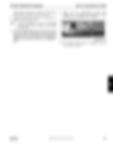
Adjust the four counterweight leveling bolts (Figure 4-14) to eliminate any relative movement between the counterweight and the turntable.
BOLT
It may be necessary to jog the counterweight removal control levers to install the counterweight pin assemblies.
Secure the counterweight to the superstructure with the two counterweight pin assemblies. To secure each pin assembly, push it in and turn it so its roll pin engages the related catch on the counterweight. Then release the pin assembly so its spring can hold the pin assembly in place.
FIGURE 4-14 9.
The crane is now ready for operation with the counterweight installed.
4
Published 05-23-08, Control # 072-05
4-23


