14 minute read
RT700E OPERATOR’S MANUALSET-UP AND INSTALLATION


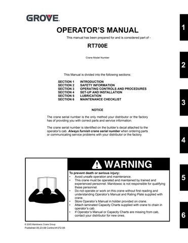
Upper Boom Nose Sheaves
Hookblock Sheaves
Upper Boom Nose Sheaves
Hookblock Sheaves
To Main Hoist
Published 05-23-08, Control # 072-05
Bottom Boom Nose Sheaves
Boom Nose Dead End
Bottom Boom Nose Sheaves
Hookblock Dead End
ERECTING AND STOWING THE BI-FOLD BOOM EXTENSION
Caution
If the boom extension fly section (stinger) is not to be erected, it should remain on the stowage brackets on the side of the boom.
Danger
Before attempting to erect or stow the boom extension; read and strictly adhere to all danger decals installed on the boom/boom nose, boom extension, and stowage brackets.
Danger
Lifting over the bi-fold extension base section is strictly prohibited, when the fly extension is either erected or folded along side of extension base section.
Erecting
1. Fully extend and set the outriggers.
2. Position the boom over the front.
3. If extended, fully retract all the boom sections and lower the boom to minimum elevation to permit ease of installation of pins and access to the boom nose.
NOTE: The auxiliary boom nose (rooster sheave) does not have to be removed. However, if reeved, the hoist cable must be removed from the sheave.
4. Rig either the main hoist or optional auxiliary hoist cable for single part line with nothing but the wedge socket on the end of the cable.
5. Extend the boom enough to disengage the spring loaded boom stop block (Figure 4-7).
6. Pull down on the rubber hook to disengage the spring loaded boom stop block. Place the end of the rubber hook in the retainer plate. Fully retract the boom.
NOTE: When the boom retracts, the rubber hook will be released allowing the stop block to engage when the boom is extended.
7. Remove the retainer clips from the attachment pins stowed in the base of the boom extension and insert the attachment pins through the attachment and anchor fittings on the right side of the boom nose. Install the retainer clips in the attachment pins.
NOTE: If erecting the boom extension fly section with the boom extension base section, skip to step 12. If not erecting the boom extension fly section, perform steps 8 to 11 and skip step 12.
8. Remove retainer clip from base to fly attachment pin and remove attachment pin from base section to fly section attachment fittings.
9. Stow the pin in the opposite attach fitting or the stowage lug.
10. Ensure the pin attaching the fly section to the boom base section rear stowage bracket (Figure 4-8, Detail D) is in place.
11. At fly section sheave end (Figure 4-8, Detail E) push in on the spring loaded latch hook to release latch, allowing the base to separate from the fly.
12. Remove the pin attaching the fly extension section to the boom base section rear storage bracket (Figure 4-8, Detail D). Ensure that the latch hook at the fly section sheave end (Figure 4-8, Detail E) is latched.
13. Remove the lock hitch pin securing the extension base to the front stowage bracket (Figure 4-8, Detail A). Stow lock hitch pin in lug provided.
14. Attach a length of rope to the extension base section tip to aid in the extension of the swingaway into place ahead of the boom nose.
NOTE: Offset Shown At 25 Degrees. To Obtain 45 Degree Offset, Remove Pin (Item 10) And Stow
ItemDescription
1Pusher Bar
2Collar Clamp
3Adjustment Bar
4Push Bar Assembly
5Hitch Pin
6Clip Pin
Caution
If the fly section remains on the extension base, do not extend the extension assembly to far, as the nose of the extension fly section could contact the front stowage bracket and cause damage.
15. Raise the boom to horizontal and extend the boom just enough to clear the extension stowage lugs from the guide ramps and stowage pins on the front and rear stowage brackets.
16. Remove the hitch pin and clip pin securing the boom extension alignment device in the stowed position. Pull
FIGURE 4-8 continued the push bar assembly out to the working position and secure it in place with the hitch pin and clip pin.
Danger
When erecting the boom extension, ensure that all personnel and equipment are kept clear of the swing path.
17. Slightly raise and/or lower the boom to help control the extension. Using the rope attached to the tip of the extension, swing the extension into place ahead of the boom nose, engaging the anchor fittings with the attachment fittings on the left side of the boom nose.
Danger
Do not modify the attach points to permit the installation of the attach pins.
18. Install the attachment pin into the upper anchor and attachment fitting on the left side of the boom nose. Install retainer clip in attachment pin.
NOTE: If the boom extension alignment device does not properly align the anchor and attachment fittings to allow installation of the last attachment pin, refer to the Service Manual and adjust the boom extension alignment device.
19. Fully retract the boom until the bottom extension anchor fitting is against the boom extension alignment device and install the attachment pin in the lower anchor and attachment fittings on the left side of the boom nose. Install the retainer clip in the attachment pin.
20. Lower the boom and remove the rope from the tip of the extension base section.
21. Remove the hitch pin and clip pin securing the boom extension alignment device in the working position. Push the push bar assembly back to the stowed position and secure it in place with the hitch pin and clip pin.
Danger
Do not attempt to erect the fly section unless it was attached to the boom extension base section during the initial erection procedure.
22. Erect the boom extension fly section as follows: a. Attach a length of rope to the tip of the extension fly section to aid in swinging the fly into place ahead of the base section. Ensure that the right base to fly extension attachment pin is in place. b. Position the boom to horizontal. c. At the fly section sheave end (see detail E), push in on the spring loaded latch hook to release the latch allowing fly to separate from the base.
Danger
When erecting the extension fly section, ensure that all personnel and equipment are kept clear of the swing path.
d. Slightly raise and/or lower the boom to help control the extension fly. Using the rope attached to the tip of the fly section, swing the fly into place ahead of the extension base, engaging the anchor fittings with the attachment fittings on the left side of the base section. e. Install the attachment pin into the anchor and attachment fittings on the left side of the base section. f. Lower the boom and remove the rope from the tip of the extension.
NOTE: Refer to Setting The Extension Offset in this Section to obtain a 25 or 45 degree offset with the swingaway.
23. Remove the cable retainer pins and clip pins from the tip of the extension base section or extension fly section.
NOTE: For zero (0) degree offset, leave the mast assembly in the stowed position.
24. Remove the mast assembly clip pin and pin from the stowed position on the extension and raise the mast assembly to an upright position. Install the pin and clip pin. Remove the cable retainer pin and clip pin from the mast.
NOTE: The hoist cable is not routed over the base extension sheave when using the fly extension.
25. Route the hoist cable over the mast sheave, the rollers on the adapter, the roller on the fly extension, and the sheave on the extension tip. Install the cable retainer pins and clip pins.
NOTE: Do not reeve hoist cable through sheaves on the main boom nose.
26.Rig the hoist cable.
Stowing
NOTE: The boom extension must be set at the zero (0) degree offset. Refer to Setting The Folding Swingaway Offset in this section.
NOTE: If so equipped, the folding fly section must be stowed on the side of the base section.
1. Fully retract the boom and swing it over the front.
2. Lower the boom to minimum elevation.
3. Remove the cable retainer pins and clip pins from the swingaway tip and mast assembly. Remove the hoist cable from the extension sheave and or mast. Install the cable retainer pins and clip pins.
4. Remove the mast assembly pin and clip pin securing the mast in the upright position. Lay the mast over to the stowed position and install the mast assembly pin and clip pin.
5. If erected, stow the extension fly section as follows: a. Attach a length of rope to the fly extension tip. b. Raise the boom to horizontal. c. Remove the retainer clip and attachment pin from the anchor and attach fittings on the left side of the base section and stow in the base section.
Danger
When stowing the extension fly, ensure that all personnel and equipment are kept clear of the swing path.
d. Slightly raise and/or lower the boom to help control the extension fly. Using the rope attached to the tip of the fly section, swing the fly to the side of the base section.
e. Elevate the boom and push in on the fly section to engage the spring loaded latch hook (see detail E) on the base section. Ensure the latch hook is properly engaged.
f. Lower the boom and remove the rope from the fly section.
6. Remove the pin and clip pin securing the boom extension alignment device in the stowed position. Pull the alignment device out to the working position and secure it in place with the pin and clip pin.
7. Lower the boom to minimum elevation.
8. Attach a length of rope to the base extension tip.
9. Raise the boom to horizontal.
10. Remove the retainer clips and attach pins from the anchor and attachment fittings on the left side of the boom nose and stow them in the base of the base extension.
11. Extend the boom enough so that the extension base and fly stowage lugs will line up in front of the guide ramps and pins on the stowage brackets when the swingaway is positioned to the side of the boom.
Danger
When stowing the extension, ensure that all personnel and equipment are kept clear of the swing path.
12. Raise and/or lower the boom to help control the swingaway and using the rope attached to the tip of the base extension, swing the base extension to the side of the boom.
13. Elevate the boom and push in on the extension to align the stowage lugs on the extension with the guide ramps and pins on the stowage brackets and fully retract the boom.
Danger
During disengagement of the stop block, extend the boom only enough to free the block. Extending the boom too far will cause the base extension to slide off the guide ramps and allow the extension to swing.
14. Lower the boom and extend the boom only enough to disengage the spring loaded boom stop block.
15. Pull down on the rubber hook to disengage the spring loaded boom extension stop block (Figure 4-9). Place the end of the rubber hook in the retainer plate. Fully retract the boom.
NOTE: When the boom retracts, the rubber hook will be released allowing the stop block to engage when the boom is extended.
16. Ensure that all the stowage lugs on the base and fly are fully engaged with the pins on the stowage brackets.
17. Insert lock hitch pin. Install the pin securing the extension base to the front stowage bracket (Figure 4-8, Detail A). Ensure the lock hitch pin is pushed all the way in.
18. Install the pin attaching the fly section to the boom base section stowage bracket (Figure 4-8, Detail D).
NOTE: If the extension fly section remained on the boom stowage brackets, perform steps 19 thru 22.
19. Remove retainer clip and attachment pin from the bushing on base section.
20. Insert the attachment pin into the base section to fly section attachment fittings and install the retainer pin.
21. Ensure the spring loaded latch hook is engaged on fly section sheave end (Figure 4-8, Detail E).
22. Ensure the pin attaching the fly section to the boom base section stowage bracket (Figure 4-8, Detail D) is in place.
23. Remove the retainer clips and attachment pins from the anchor and attach fittings on the right side of the boom nose and stow them in the base of the swingaway.
24. Remove the clip pin and pin securing the boom extension alignment device. Place the boom extension push bar assembly in the stowed position and secure it in place with the pin and clip pin.
Danger
Failure to maintain the proper clearance between the base extension anchor fittings and the boom nose attach fittings could cause these fittings to contact each other during operation of the boom.
25. Extend the boom enough to engage the boom stop block.
26. Rig the boom nose and hoist cable as desired and operate the crane using normal operating procedures.
Setting The Folding Swingaway Offset
Danger
Ensure any blocking material used is adequate to support the weight of the extension assembly without tipping or falling.
1. Extend and set the outriggers and swing the boom to over the front. Position the boom to above horizontal.
2. Block up under the tip of the extension assembly section.
3. To set the offset from a lesser degree to higher degree perform the following procedures.
Caution
Do not overload the extension anchor fittings or the extension base section when lowering the boom.
a. Slowly lower the boom until the pressure is relieved on the offset link pins.
NOTE: For 25 or 45 degree offset, make sure the mast is in the raised position.
b. Remove the offset link clip pins and attach pins securing the offset links in the lesser degree offset position. If going to maximum offset stow them in the stowage lugs. If going to the intermediate (25 degree) offset install them in the offset links for that degree of offset.
c. Slowly elevate and telescope the boom at the same time so that the extension does not move off of the blocking until the offset links take the full weight of the extension.
d. Reeve the hoist cable as described under normal erecting procedures.
4. To set the offset from higher degree to lesser degree, perform the following procedures.
Caution
Do not overload the extension anchor fittings or the extension base section when lowering the boom.
a. Slowly lower the boom until the pressure is relieved from the offset links.
b. Remove the offset link clip pins and attachment pins and lower the boom until the holes for the lesser degree offset position align in the offset links. Install the offset pins and clip pins.
c. Slowly elevate and telescope the boom at the same time so that the extension does not move off of the blocking until the offset links take the full weight of the extension.
d. Reeve the hoist cable as described under normal erecting procedures.
ERECTING AND STOWING THE BI-FOLD BOOM EXTENSION USING THE 6.1 M (20 FOOT) INSERT
Danger
Before attempting to erect or stow the bi-fold extension with insert, read and strictly adhere to all danger decals installed on the boom/boom nose, boom extension, insert, and stowage brackets.
Erecting
1. Fully extend and set the outriggers.
2. Position the boom over the front.
3. If extended, fully retract all the boom sections and lower the boom to minimum elevation to permit ease of installation of pins and access to the boom nose.
ItemDescription
1Boom Nose Upper Sheaves
2Cable Roller
3Insert Attachment Pins
4Insert Attachment Pins Stowage Lugs
56.1 m (20 foot) Insert
6Bi-Fold Extension Attachment Pins
NOTE: The auxiliary boom nose (rooster sheave) does not have to be removed. However, if reeved, the hoist cable must be removed from the
ItemDescription
7Boom Nose Lower Sheaves
8Boom Extension Attachment Pins
9 Bi-Fold Extension Attachment Pins Stowage Lugs
10Offset Link Pins
11Zero Degree Offset Holes
Published 05-23-08, Control # 072-05
5. Extend the boom as necessary to permit sufficient clearance for installation of the 6.1 m (20 foot) Extension Insert; then lower it until the tip of the bi-fold extension assembly is laying on the ground. Block up under the bifold extension, approximately 2.4 to 3.0 m (8 to 10 ft) ahead of the boom nose.
6. Remove the four retainer clips and attachment pins that secure the bi-fold extension to the boom nose.
7. Retract the boom leaving the bi-fold extension on the blocking.
8. Using the main or auxiliary hoist cable, lift the Insert by the lifting lugs and position it at the base end of the bifold extension.
9. Mate the Insert to the bi-fold extension and install the four attaching pins and retainer clips removed in step 6.
10. With the hoist cable still attached to the Insert, lift the assembled unit and move the blocking, erected in step 5, to approximately 2.4 to 3.0 m (8 to 10 ft) ahead of the boom nose attach end of the Insert.
NOTE: Repeat steps 6 through steps 16 in a similar manner to install the second Insert if applicable.
11. Lower the bi-fold and insert assembly onto the blocks and detach the hoist cable.
12. Retract the boom and lower to minimum elevation.
13. Rig the hoist cable for single part line with nothing but the wedge socket on the end of the cable.
14. Extend the boom and mate the attachment lugs on the Insert with the anchor fittings on the boom nose. It may be necessary to raise or lower the boom slightly to mate the attach lugs.
NOTE: If the Insert attach lug holes are not in lateral alignment with the holes in the boom nose anchor fittings to install the pins, adjust the upper and lower cross strut adjustment screws on the Insert to align the holes.
15. Remove the retainer clips from the four attachment pins stowed on the Insert and install them in the attachment and anchor fittings on both sides of the boom nose. Install the retainer clips.
Caution
Do not attempt to swing the boom extension around to the right side of the insert. This could result in damage to the insert.
16. Slowly elevate the boom and remove the blocking from under the Insert and bi-fold extension.
17. Refer to steps 22 thru 26 of Erecting The Boom Extension to erect the fly section, to set the offset, and rig the hoist cable.
Stowing
NOTE: If so equipped, the folding fly section must be stowed on the side of the base section.
1. If the fly section is erected, refer to steps 1 thru 5 of Stowing The Bi-Fold Boom Extension.
2. Extend the boom approximately 1.22 to 1.52 m (4 to 5 ft). Lower the boom until the sheave is on the ground.
3. Block up under the insert approximately 2.4 to 3 m (8 to 10 ft) forward of the boom nose.
4. Remove the retainer clips from the four pins in the attachment and anchor fittings and remove the attachment pins. Stow the pins in the holders on the insert.
5. Retract the boom disengaging the anchor fittings on the boom nose from the attaching lugs on the insert.
6. Attach a hook to the hoist cable.
7. Attach the hoist cable hook to the lifting lugs on the insert. Lift the assembly and reposition the blocking approximately 2.4 to 3 m (8 to 10 ft) forward of the insert to swingaway attachment points.
8. While supporting the insert with the hoist cable, remove the retainer clips from the four pins attaching the insert to the swingaway. Remove the four pins.
9. Remove the insert and position it to one side of the crane.
10. Position the boom and extend it to engage the boom nose with the swingaway. Install the four attachment pins and retainer clips removed in step 8.
11. Stow the swingaway on the side of the main boom using steps 6 thru 26 of Stowing The Swingaway Boom Extension.