26 minute read
RT700E OPERATOR’S MANUALOPERATING CONTROLS AND PROCEDURES


steer control valve to allow the operator to safely steer the crane to a safe stop.
The LOW STEER PRESSURE (PRESS) indicator comes on during pressure drops. This indicates the secondary steering system should also be working.
throttle until maximum first gear speed is attained and shift into the second (2) gear position.
4. Repeat the above procedure for the third (3) gear position until the desired travel speed is attained.
Caution
Do not downshift to a lower gear if the road speed is greater than the maximum speed of the lower gear.
Traveling - Reverse
Traveling in reverse is accomplished the same way as traveling forward, except for shifting the transmission shift lever to reverse (R) position and rotating the knob to the 1, 2, and 3 positions. (Refer to TRAVELING - FORWARD.)
Caution
Apply service brakes and bring crane to a complete stop before shifting transmission into reverse.
Four-Wheel Drive Operation
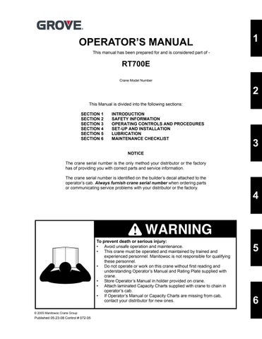
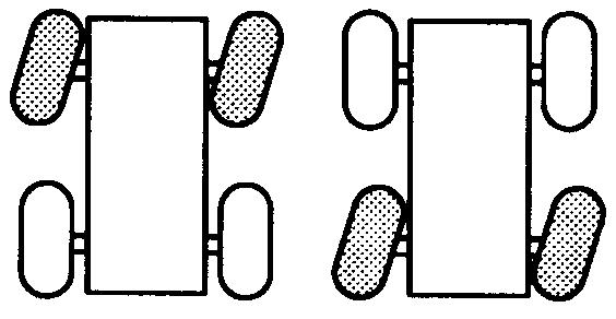
Crabbing
Crabbing is accomplished with the steering wheel and the REAR STEER control switch . Depending upon which direction the operator wishes to travel (crab), the steering wheel is turned in the same direction as the REAR STEER control switch. This permits driving the crane forward or backward in a crabbing manner
Traveling - Forward
Caution
Engage the swing lock pin for extended travel.
1. After the engine has warmed up, position the transmission shift lever from neutral (N) to forward (F) position.
2. Position the DRIVE AXLE switch to either 2WD-HI or 4WD-LO.
Caution
Use four wheel drive only when more traction is required.
NOTE: If service brake hydraulic accumulator pressure is low, the parking brake cannot be released.
3. Put the transmission shift lever knob to the first (1) gear position and release the parking brake. Depress the foot
If more traction is required due to slipping or spinning wheels, engage the front axle drive as follows:
Caution
Before shifting from two-wheel drive to four wheel drive (or from four back to two), crane travel must be stopped.
1. Position the DRIVE AXLE selector switch to 4WD LO.
2. Select gear speed and direction of travel.
3. Return the DRIVE AXLE selector switch to the 2WD HI position as soon as two-wheel traction will suffice.
Travel On Slopes
Observe the following when operating a crane on a slope:
• The slope -- side to side or fore and aft -- must not exceed 15% (8.5 degrees).
• Travel must be on an improved surface or on hardpacked dry earth having a minimum 0.5 coefficient of adhesion.
• Travel must be limited to a forward direction only.
• Travel must not exceed a speed of 1 mph.
• All boom sections must be fully retracted.
• The boom extension must be in the stowed position or removed from the crane.
• The boom must be lowered to horizontal and positioned over the front of the crane.
• The swing brake and turntable lock pin must be engaged.
• The hook block may be reeved over the main boom nose; the overhaul ball may be reeved over the main boom nose or auxiliary boom nose. Each must be secured at the tiedown on the carrier to prevent swinging.
• Tires must be inflated to the recommended pressure for pick and carry operations.
• The hydraulic tank must be filled to the specified level. The fuel tank must be over half full.
• No loads may be supported by the boom (such as no pick and carry loads) while traveling on a slope.
• All cribbing and other nonstandard accessories must be removed from the crane.
• Avoid holes, rocks, extremely soft surfaces, and other obstacles that might subject the crane to undue stresses and possible overturning.
• Travel must be conducted with the assistance of a ground person to warn the operator of any changing conditions of the terrain being traversed.
Proper Operation Of Differential Lock
Caution
When using the differential lock, steering characteristics may be affected.
Caution
Try to use four wheel drive to gain adequate traction before using the differential lock.
Caution
Do not operate the differential lock while the crane is moving; when traveling downhill; at speeds above 10 mph; on hard, dry surfaces; during axle spin-out.
NOTE: The differential lock will not operate unless the DRIVE selector switch is in the 4WD LO position.
General
The purpose of the differential lock is to provide maximum traction and control on poor road or highway surfaces. When the differential locks are actuated, the clutch collar completely locks the differential case, gearing, and axle shafts together, thus maximizing traction to both wheels of each axle. The lock position will also protect against spinout.
When normal driving conditions exist (during periods of good traction), the differential locks should not be actuated. The axles should be allowed to operate with differential action between both wheels.
When using the differential locks, the operator must remember the following:
1. The AXLE DIFF control switch is a momentary rocker switch and must be held in the LOCK position.
2. The differentials can be locked or unlocked when the vehicle is standing still or at a constant low speed when the wheels are not slipping.
3. Lock the differentials and operate the vehicle only at low speeds.
4. When the differentials are locked, the crane’s turning radius will increase, creating an understeer condition. The operator must use caution, good judgement and drive at low speeds when operating the vehicle with a locked differentials.
NOTE: Turning on hard surfaces with locked differentials should be avoided.
5. Lock the differentials only when maximum traction is needed on poor road or highway surfaces.
6. Always unlock the differentials when the need for maximum traction has passed or when traveling on good road or highway surfaces.
7. Do not lock the differentials when the wheels are slipping. Damage to the differentials can result.
8. Do not lock the differentials when the vehicle is traveling down steep grades and traction is minimal. Potential loss of vehicle stability can result.
Operation
The differential lock (AXLE DIFF) should preferably be engaged when the crane is stationary but may be engaged when moving if the following conditions are met.
1. The crane is moving very slowly (creep speed).
2. The wheels are not spinning at the time of engagement. When traveling with the lock engaged do not deviate from a straight path more than is absolutely necessary.
1. When operating the differential lock, position the switch to the locked position with the crane stationary or at slow speed.
2. If moving at slow speed, let up momentarily on the accelerator to relieve torque on the differential gearing. This will fully engage the differential locks. When activated the square amber LED on the switch should be illuminated.
3. Proceed over the poor road condition cautiously.
When the adverse condition has passed, adhere to the following:
1. Position the differential lock (AXLE DIFF) switch to the UNLOCK position while maintaining slow speed.
2. Let up momentarily on the accelerator to relieve torque on the differential gearing, allowing the differential to fully unlock. The square amber LED on the switch should go out.
3. Resume driving at a normal speed using good driving judgement.
Proper Operation Of Axle Oscillation Lockouts
NOTE: The following procedure should be used to periodically check the axle oscillation system and ensure that it is in proper working condition.
1. Ensure the tires are inflated to the recommended pressure. Refer to the Load Chart Book in the crane cab for proper inflation pressures.
2. With the hook unloaded, the boom fully retracted and centered over the front at no more than a 10 to 15 degree boom angle, position the crane on a block or curb so that one rear tire is approximately 15 to 30 cm (6 to 12 inches) above the level of the opposite tire.
3. Slowly swing the superstructure to the right or left until the axle oscillation lockout valve is activated. This will lock the rear axle out of level. Do not swing beyond the tire track.
4. After engaging the swing brake, slowly drive off of the block or curb and stop. The rear tires should both be touching the road surface and the opposite front tire should be light or slightly off the road surface.
5. Release the swing brake and swing the superstructure until it is centered over the front.
Caution
Do not operate the crane if the axle oscillation lockout system is not functioning properly.
6. If the axle oscillation lockout valve is functioning properly, the crane will not re-level itself. If the rear axle does not lock or unlock properly, evaluate the lockout system and repair as necessary.
General Crane Operation Pump Drive
Hydraulic pump No. 1 is a two section gear pump and is mounted on the torque converter drive pad. Pump No. 2 is a single section pump mounted on the right side of the engine.
Pump No. 3 is a single section pump mounted on the torque converter drive pad. The pumps operate any time the engine is running.
Setting The Park Brake When Crane Is On Outriggers
When operating the crane on outriggers, the transmission should be shifted into 4WD (four-wheel-drive) and the parking brake set in order to keep the rear drive axle from rotating. This rotating is caused by a small amount of drag in the hydraulic clutch, resulting in rotation of the rear wheels. When this procedure is correctly followed, the wheels will not rotate with the crane on outriggers during any crane function.
Control Lever Operation
The control lever operation for all crane functions is standard, i.e. the closer the lever is to neutral (center), the slower the system responds. The control lever should be returned to neutral to hold the load. Never feather the hoist control lever to hold the load.
NOTE: Always operate the control levers with slow, even pressure.
Preload Check
After the crane has been readied for service, an operational check of all crane functions (with no load applied) should be performed. The Preload Check is as follows:
Caution
Operate engine at or near governed rpm during preload check of crane functions.
NOTE: Carefully read and become familiar with all crane operating instructions before attempting a preload check or operating the crane under load.
1. Extend and set outriggers.
2. Raise, lower, and swing the boom a minimum of 45° right and left.
3. Telescope the boom in and out.
4. Raise and lower the cable a few times at various boom lengths. Ensure there is no kinking.
Using Your Load Chart
NOTE: One of the most important tools of every Grove crane is the load chart found in the crane operator’s cab. Terms to know are shown in (Figure 3-5).
The load chart contains a large amount of information, which must be thoroughly understood by the operator.
The load chart contains four outrigger capacity charts: fully, mid, and retracted outriggers main boom and boom extension with full outriggers. In addition, the load chart contains three on-rubber capacity charts: over front stationary, 360° stationary, and pick and carry over front.
Another section contains the notes for lifting capacities. Be sure to read and understand all the notes concerning lifting capacities.
The load chart also gives weight reductions for Grove load handling devices such as hook blocks, headache balls, boom extensions, etc., which must be taken into consideration as part of the load. Remember, the weight of any other load handling devices such as chains, slings, or spreader bars must be added to the weight of the load.
Crane Functions
The capacity charts are divided into structural strength and stability limits. This is shown by the bold line across the chart. Capacities above the line are structural strength limits and capacities below the line are stability limits.
The left column is the load radius, which is the distance from the center of crane rotation to the load center of gravity. The top row lists various boom lengths ranging from fully retracted to fully extended with the swingaway jib. The number at the intersection of the left column and top row is the total load capacity for that load radius and boom length. The number in parentheses below the total load capacity is the required boom angle (in degrees) for that load. Boom lengths between increments should always be treated as if it were the next longer length. For example, if the actual boom length is 50 ft and the chart shows boom lengths of 48 and 54 ft, use the load capacity shown in the 54 ft column.
Another important section is the range diagram. The range diagram shows the operating radius and tip height that can be achieved at a given boom length and angle. If the operator knows the radius a nd tip height required for a specific lift, the angle and boom length can be quickly determined from the range diagram. Or, if the boom length and angle are known, the tip height and operating radius can be quickly determined.
A lifting diagram is included to describe over side, over rear, and over front lifting areas. The lifting area diagram shows that the locations of the outrigger stabilizer cylinders in the full extended position are used to mark the boundaries of the lifting areas.
A boom extension capacity chart and notes are included to list the capacities for the extension length, load radius, and boom angle.
Danger
Death or serious injury could result from improper crane setup on outriggers.
Danger
The outriggers must be properly extended and set and the crane level before any other operation of the crane on outriggers is attempted.
Danger
When operating the crane on outriggers, the outriggers should always be fully extended or locked in the midextend position, depending on the load chart being used.
Setting The Outriggers
1. Position the outrigger floats directly out from each outrigger to where the outriggers will be properly extended.
Caution
Always depress one of the outrigger/selector switches before positioning the outrigger extension/retraction switch to extend or retract. Failure to do this may cause a hydraulic lock against the individual solenoid valves, preventing them from opening.
2. Press the appropriate rocker switch on the outrigger selector panel for extending the desired outrigger and hold the OUTRIGGERS EXTEND/RETRACT rocker switch to EXTEND. The chosen outrigger beam should begin to extend. Refer to Engaging the Mid-Extend Lock Pin if the crane is to be operated with the outriggers at the mid-extend position. Extend each outrigger in turn.
Warning
All four outrigger beams must be equally extended to the mid position vertical stripe or fully extended or retracted position before beginning operation.
NOTE: More than one outrigger at a time may be extended. However, to ensure that each outrigger is fully extended, repeat step 2 for each outrigger after a multi-outrigger extension.
3. After all four outrigger beams have been fully extended, press the appropriate rocker switch on the outrigger selector panel for extending the desired stabilizer and hold the OUTRIGGERS EXTEND/RETRACT rocker switch to EXTEND. Extend each stabilizer in turn.
4. Extend each stabilizer, positioning the float as necessary, until the locking levers of the float engage the stabilizer cylinder rod. Verify each float is secure on its related stabilizer cylinder rod.
NOTE: More than one stabilizer may be extended at one time.
5. With each stabilizer float firmly touching the ground, extend the front stabilizers approximately 8 to 10 cm (3 to 4 inches).
6. Extend the rear stabilizers approximately 8 to 10 cm (3 to 4 inches).
Caution
All four outrigger beam lock pins must be engaged before operating from the mid-extend position.
Caution
The operator must select the proper load chart and LMI program for the outrigger position selected.
7. Repeat steps 5 and 6 until all wheels are clear of the ground and the crane is level as indicated by the sight level bubble located inside the cab.
NOTE: If it is suspected that the bubble level indicator is out of adjustment, verify and adjust the bubble level as follows: a. Locate the crane on a firm, level surface. b. Extend and set the outriggers. Level the crane, as indicated by the bubble level indicator, using the outriggers. c. Place a miracle pointer level, carpenter level, or similar type device on a machined surface such as the turntable bearing or bearing mounting surfaces. d. Using the outriggers, level the crane as indicated on the leveling device used in step c. e. Using the bubble level indicator mounting screws, adjust the bubble level indicator to show level.
Engaging The Mid-Extend Lock Pin
1. Turn the locking pin 90° from its stowed position and allow the pin to rest on top of the outrigger beam.
NOTE: It may be necessary to use the appropriate outrigger extension switch and jog the OUTRIGGERS EXTEND/RETRACT switch slightly to ensure proper pin engagement.
2. Slowly extend or retract the outrigger beam, allowing the locking pin to drop into the hole in the top of the outrigger beam, engaging the outrigger beam at the desired length.
Stowing The Outriggers
1. Select the rear stabilizers with the appropriate rocker switches and hold the OUTRIGGERS EXTEND/ RETRACT switch to RETRACT until the rear stabilizers have retracted several inches.
2. Select the front stabilizers with the appropriate rocker switches and hold the OUTRIGGERS EXTEND/ RETRACT switch to RETRACT until the front stabilizers have retracted several inches.
3. Repeat steps 1 and 2 until the crane is resting on all four wheels and the stabilizer floats are several inches off the ground.
Danger
Keep feet and hands clear of floats when unlocking the floats from the stabilizers.
4. Release the locking levers and allow the floats to drop to the ground.
5. Continue to retract the stabilizers until they are fully retracted.
6. Press the appropriate rocker switch on the outrigger selector panel for retracting the desired outrigger and hold the OUTRIGGERS EXTEND/RETRACT rocker switch to RETRACT. The chosen outrigger beam should begin to retract.
NOTE: More than one outrigger may be retracted at one time.
7. After all outriggers have been fully retracted, stow the outrigger floats. Pin them to their front and rear stowing points with quick pins.
Stowing The Mid-Extend Lock Pin
1. Retract the outrigger extension cylinder.
NOTE: If the lock pin is wedged in the hole in the outrigger beam, it may be necessary to jog the OUTRIGGERS EXTEND/RETRACT switch slightly while pulling upward on the pin.
2. Lift the lock pin and turn it 90° to its stowed position.
Swinging The Boom (Single Axis Controller Option)
Danger
Death or serious injury could result from being crushed by moving machinery. Before activating swing, sound the steering wheel horn and verify that all personnel are clear of rotating and moving parts.
Warning
Keep the areas in the swing path of the hook, load and tail clear of all obstructions and personnel.
Caution
Disengage the swing brake and the swing lock pin or 360° swing lock before attempting to swing.
Caution
The operator must select the proper load chart and LMI program for the outrigger position selected.
Caution
Never push or pull the swing control lever through neutral to the opposite direction to stop swing motion. Use the swing brake foot pedal to stop swing rotation.
NOTE: Automatic rear axle oscillation lockout will activate when the boom swings right or left of the crane centerline.
To swing the turntable right (clockwise), push the SWING control lever forward away from yourself. To swing the turntable left (counterclockwise), pull the swing control lever back, toward yourself. Always operate the control level with a slow, even pressure. Use the swing brake foot pedal to stop rotation, then position the SWING BRAKE switch to ON to prevent further rotation.
Elevating The Boom (Single Axis Controller Option)
Warning
Keep the area above and below the boom clear of all obstructions and personnel when elevating the boom.
To elevate the boom, pull the BOOM (lift) control lever back, toward yourself, and hold until the boom reaches the desired elevation level.
Lowering The Boom (Single Axis Controller Option)
Warning
Keep the area beneath the boom clear of all obstructions and personnel when lowering the boom.
WARNING
Long cantilever booms can create a tipping condition, even when unloaded and in an extended, lowered position.
Caution
When lowering the boom, simultaneously let out the hoist cable to prevent two-blocking the boom nose and hook block.
Caution
The closer the load is carried to the boom nose, the more important it becomes to simultaneously let out the hoist cable as the boom is lowered.
To lower the boom, push the BOOM control lever forward, away from yourself, and hold until the boom is lowered to the desired position.
Extending The Boom (Single Axis Controller Option)
Warning
When extending the boom, simultaneously let out the hoist cable to prevent two-blocking the boom nose and hook block.
Danger
Check the load chart for the maximum load at a given radius, boom angle, and length before extending the boom with a load.
Caution
Before extending the boom, ensure the large access cover on top of the boom base section is installed.
NOTE: When the crane is equipped with an auxiliary hoist, the telescope function is controlled by a foot pedal.
To extend the boom, push the TELESCOPE control lever forward, away from yourself, and hold until the boom extends to the desired length.
Retracting The Boom (Single Axis Controller Option)
Warning
When retracting the boom, the load will lower unless the hoist cable is taken in at the same time
To retract the boom, pull the TELESCOPE control lever back, toward yourself, and hold until the boom retracts to the desired length.
Extending and Retracting the Boom With the Telescope Control Pedal (Single Axis Controller Option)
The telescope control pedal is used on a crane equipped with an auxiliary hoist. Push on the top of the pedal to extend the boom and push on the bottom of the pedal to retract the boom.
Lowering And Raising The Hoist Cable (Single Axis Controller Option)
Warning
Keep the area beneath the load clear of all obstructions and personnel when lowering or raising the cable (load).
Warning
Do not jerk the control lever when starting or stopping the hoist. Jerking the lever causes the load to bounce, which could result in possible damage to the crane.
NOTE: When the load is stopped at the desired height, the automatic brake will engage and hold the load as long as the control lever remains in neutral.
Lowering The Cable
Push the MAIN or AUX HOIST control lever forward, away from yourself, and hold until the hook or load is lowered to the desired height.
Raising The Cable
Pull the MAIN or AUX HOIST control lever back, toward yourself, and hold until the hook or load is raised to the desired height.
Hoist Speed Range
Selection (Single Axis Controller Option)
Caution
Do not change the hoist speed range with the hoist rotating.
To change the speed range of the hoist, position the applicable switch (MAIN HOIST SPEED or optional AUX HOIST SPEED) to HIGH or LOW as applicable.
Swinging the Boom (Dual Axis Controller Option)
Danger
Death or serious injury could result from being crushed by moving machinery. Before activating swing, sound the steering wheel horn and verify that all personnel are clear of rotating and moving parts.
Warning
Keep the area beneath the boom clear of all obstructions and personnel when lowering the boom.
Caution
The operator must select the proper load chart and LMI program for the outrigger position selected.
Caution
Never push or pull the swing control lever through neutral to the opposite direction to stop swing motion. Use the swing brake foot pedal to stop swing rotation.
NOTE: Automatic rear axle oscillation lockout will activate when the boom swings right or left of the crane centerline.
To swing the boom, push the controller on the left hand armrest to the right for ri ght swing (rotates turntable clockwise), or to the left for left swing (rotates turntable counterclockwise). Always operate the control lever with a slow, even pressure. Use the swing brake foot pedal to stop rotation, then position the SWING BRAKE switch to ON to prevent further rotation.
Elevating the Boom (Dual Axis Controller Option)
Warning
Keep the area above and below the boom clear of all obstructions and personnel when elevating the boom.
To elevate the boom, push the controller on the right hand armrest to the left (raises the boom), and hold until the boom reaches the desired elevation.
Lowering the Boom (Dual Axis Controller Option)
Warning
Keep the area beneath the boom clear of all obstructions and personnel when lowering the boom.
Warning
Long cantilever booms can create a tipping condition, even when unloaded and in an extended, lowered position.
Caution
When lowering the boom, simultaneously let out the hoist cable to prevent two-blocking the boom nose and hook block.
Caution
The closer the load is carried to the boom nose, the more important it becomes to simultaneously let out the hoist cable as the boom is lowered.
To lower the boom, push the controller on the right hand armrest to the right (lowers the boom) and hold until the boom is lowered to the desired position.
Extending the Boom (Dual Axis Controller Option)
Warning
When extending the boom, simultaneously let out the hoist cable to prevent two-blocking the boom nose and hook block.
Danger
Check the load chart for the maximum load at a given radius, boom angle, and length before extending the boom with a load.
Caution
Before extending the boom, ensure the large access cover on top of the boom base section is installed.
To extend the boom, push the controller on the left hand armrest forward and hold until the boom reaches the desired length.
Retracting the Boom (Dual Axis Controller Option)
WARNING
When retracting the boom, the load will lower unless the hoist cable is taken in at the same time
To retract the boom, pull the controller on the left armrest back and hold until the boom retracts to the desired position.
Extending and Retracting the Boom With the Telescope Control Pedal (Dual Axis Controller Option)
The telescope control pedal is used on a crane equipped with an auxiliary hoist. Push on the top of the pedal to extend the boom and push on the bottom of the pedal to retract the boom.
Lowering And Raising The Hoist Cable (Dual Axis Controller Option)
Warning
Keep the area beneath the load clear of all obstructions and personnel when lowering or raising the cable (load).
Warning
Do not jerk the control lever when starting or stopping the hoist. Jerking the lever causes the load to bounce, which could result in possible damage to the crane.
NOTE: When the load is stopped at the desired height, the automatic brake will engage and hold the load as long as the control lever remains in neutral.
Lowering The Cable
Push the control lever forward to MAIN HOIST DOWN or AUX HOIST DOWN, away from yourself, and hold until the hook or load is lowered to the desired height.
Raising The Cable
Pull the control lever back to MAIN HOIST UP or AUX HOIST UP, toward yourself, and hold until the hook or load is raised to the desired height.
Hoist Speed Range Selection (Dual Axis Controller Option)
Caution
Do not change the hoist speed range with the hoist rotating.
To change the speed range of the hoist(s), position the applicable switch (MAIN HOIS T SPEED or optional AUX HOIST SPEED) to HIGH or LOW as applicable.
Operational Aids
Warning
Electronic equipment on this crane is intended as an aid to the operator. Under no condition should it be relied upon to replace the use of capacity charts and operating instructions. Sole reliance upon these electronic aids in place of good operating practices can cause an accident.
Load Moment Indicator (LMI) System
The Load Moment Indicator (LMI) is an electro-mechanical sensing system designed to alert the crane operator of impending capacity when the system has been properly preset by the operator. The control panel is mounted in the dashboard of the operator’s cab. When an overload condition is sensed, the system provides the operator with a visual and audible warning, and locks out the control levers to prevent lowering the boom, extending the boom, or raising the main or auxiliary hoist cables.
CE Units
In addition to the audible warning in the cab, an audible warning alarm is also mounted on the boom in the vicinity of the lift cylinder upper pivot point to warn all personnel that a lockout has occurred.
Three additional features are included within the LMI system:
• Swing Angle Set Limitation
• Work Area Definition
• Anti-two Block Device
Swing Angle Set Limitation allows left and right swing angle to be preset. When the preset angle is reached, the system will provide an audible warning.
Work Area Definition allows the crane operator to describe the crane’s working area by setting up “virtual walls”. They are referred to as virtual walls because they exist in the system and are not real walls. The virtual walls represent obstacles (i.e. buildings, towers, poles, etc.) in the crane’s working range. They are set by defining points along the outer limits of the working area with the tip of the boom. Once the working area has been defined, the system will provide a visual and an audible warning if the boom approaches a virtual wall.
Caution
When defining virtual wall(s), always allow a safe working distance to any obstacles. Never work outside a safe working area as defined by common practice, standards, and manuals.
Warning
There are no cutouts associated with the swing angle set limitation or the work area definition features.
An Anti-two Block Device is also incorporated into the system to prevent the hook block or headache ball from coming into contact with the boom nose or boom extension. This condition will also cause a lockout of hoist up, boom down, and telescope out, and also provide a visual and an audible alarm.
Refer to the LMI Operator’s Handbook for more detailed information on the function of the LMI system.
Control Lever Lockout System
The control lever lockout system consists of hydraulic solenoid valves (located in the directional control valves) which are in series between the hydraulic remote control valves in the cab and the pilot-operated directional control valves. When the valves are actuated, they prevent pilot flow between the hydraulic remote control valve in the cab and the appropriate directional control valve. The valves are activated in such a manner as to prevent worsening the condition, i.e. boom down, telescope out, or hoist up. The control lever lockout system is used with the anti-two-block system or the load moment indicator (LMI) system.
Stowing And Parking
Warning
Never park the crane near holes, or on rocky or extremely soft surfaces. This may cause the crane to overturn, resulting in injury to personnel.
When parking the crane, do the following:
1. Park the crane on a stable surface.
2. Remove the load from the hook.
3. Stow the swingaway boom extension, if erected.
4. Fully retract the boom and position it in the normal travel position.
5. Engage the swing brake and/or swing lock pin.
6. Retract all stabilizer cylinders and outrigger beams.
7. Apply the parking brake.
8. Put all operating controls in the neutral position.
9. Position the CRANE FUNCTION switch to OFF.
10. Shut down the engine following the proper procedures specified in this Operator Manual and the applicable Engine manual.
11. Remove the keys.
Caution
To avoid possible engine fault codes and undesirable operation, ensure the keyswitch has been off 2 minutes before disconnecting batteries.
12. Disconnect batteries, if machine will be inactive for over 24 hours.
13. Close and lock all windows, covers, and doors.
Section 4
SET-UP AND INSTALLATION
General
This section provides procedures for installing the hoist cable on the hoist drum, cable reeving, and erecting and stowing the boom extension.
Installing Cable On The Hoist
Caution
If cable is wound from the storage drum, the reel should be rotated in the same direction as the hoist.
NOTE: The cable should preferably be straightened before installation on the hoist drum.
Install cable on the hoist drum in accordance with the following procedure.
1. Position the cable over the boom nose sheave and route to the hoist drum.
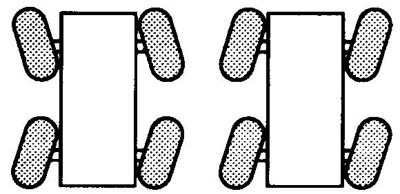
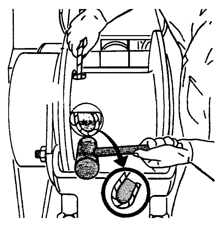
2.Position the hoist drum with the cable anchor slot on top.
3.Insert the cable through the slot and position around the anchor wedge (Figure 4-1).
NOTE: The end of the cable should be even with the bottom of the anchor wedge.
4.Position the anchor wedge in the drum slot; pull firmly on the free end of the cable to secure the wedge.
NOTE: If the wedge does not seat securely in the slot, carefully tap the top of the wedge with a mallet.
5.Slowly rotate the drum, ensuring the first layer of cable is evenly wound onto the drum.
6.Install the remainder of the cable, as applicable.
Cable Reeving
NOTE: There are two types of cable (wire rope) available on this crane; 6x37 and 35x7 (non-rotating).
Within the limits of the load and range charts and permissible line pull, multi-part lines allow the operator to raise a greater load than can be raised with a single part line. Various cable reeving (part line) is possible with the boom nose and hook block. This reeving should be accomplished by a qualified rigger using standard rigging procedures (Figure 4-6).
In order to quick reeve the hook block without removing the wedge socket on the end of the cable, see (Figure 4-2).
Published 05-23-08, Control # 072-05
DEAD-END RIGGING/WEDGE SOCKETS
Wedge socket assemblies are popular rigging accessories and have been successfully used for decades to terminate wire ropes on mobile cranes. A wedge socket assembly is easily installed and dismantled but it must be installed and used correctly. It is essential to use only a wedge and socket of the correct size for the rope fitted. Failure to do so may result in the rope pulling through the fitting.
Since state and local laws may vary, alternate attachment methods may be necessary depending upon work conditions. If alternate methods are selected, the user is responsible and should proceed in compliance with the regulations in force. If there are any questions, contact your local Grove Distributor or Manitowoc CraneCARE.
Do not mix components from different manufacturers. The selection, installation and use of a wedge socket assembly must be in accordance with the requirements of the wedge socket manufacturer and the wire rope manufacturer upon whose wire rope the wedge socket assembly will be used.
Grove Crane specifies the size, type, class and line pulls for wire rope, predominately rotation resistant wire rope, and rigging accessories such as overhaul balls and hook blocks for use with each new crane that it manufactures. Other wire ropes and rigging accessories are available from various vendors. Different wire rope manufacturers have differing requirements for the construction, handling, cutting, seizing, installation, termination, inspection and replacement of the wire ropes they produce. Their advice should be sought for each specific type of wire rope a crane user intends to install on a mobile crane.
When assembly is complete, raise the boom to a working position with a load suspended to firmly seat the wedge and rope into the socket before the crane is used operationally.
Caution
If the socket is not positioned with the flat face toward the boom sections, structural damage will occur.
When anchoring the socket to the boom, ensure the flat face of the socket is in position, as shown, toward the boom sections (Figure 4-3).
Installing Wedge And Socket
1. Inspect the wedge and socket. Remove any rough edges and burrs.
2. The end of the wire rope should be seized using soft, or annealed wire or strand. If the end of the rope is welded, the welded end should be cut off. This will allow the distortion of the rope strands, caused by the bend around the wedge, to adjust themselves at the end of the line.
FIGURE4-3
3. Make sure the live-loaded side (Figure 4-4) of the rope is directly in line with the ears of the socket and the direction of pull to which the rope will be subjected. If the rope is loaded into the socket incorrectly, under a load the rope will bend as it leaves the socket, and the edge of the socket will wear into the rope causing damage to the rope and eventual failure.
4. Insert the end of a wire rope into the socket, form a loop in the rope, and route the rope back through the socket allowing the “dead” end to protrude from the socket. Ensure the dead end of the rope is of sufficient length to apply end treatment to the dead end after the wedge has been seated.
5. Insert the wedge into the loop and pull the live end of the rope until the wedge and rope are snug inside the socket. It is recommended that the wedge be seated inside the socket to properly secure the wire rope by using the crane’s hoist to first apply a light load to the live line.
6. After final pin connections are made, increase the loads gradually until the wedge is properly seated.
7. The wire rope and wedge must be properly secured inside the socket before placing the crane into lifting service. It is the wedge that secures the wire rope inside the socket whereas the dead-end treatment is used to