4 minute read
RT700E OPERATOR’S MANUALSET-UP AND INSTALLATION


FIXED COUNTERWEIGHT Description
The counterweight Figure4-11 is pinned to the rear of the superstructure and weighs about 5550 kg (12,210 pounds). For cranes without an auxiliary hoist, an additional 672 kg (1478 pounds) counterweight is bolted to the hoist mounting area instead of the auxiliary hoist.
Maintenance
Danger
Death or serious injury could result from being crushed by a falling counterweight.
Danger
Ensure the counterweight pin assemblies are installed properly and are secure in their catches.
Removal
1. Fully extend and set the outriggers.
2. Rotate the superstructure so the counterweight is over the front of the carrier to gain additional clearance.
Caution
When lifting/handling the counterweight, keep the chains/ straps vertical to minimize side pull on the lifting lugs.
NOTE: The counterweight weighs approximately 5550 kg (12,210 pounds).
NOTE: Use of a forklift to install or remove the counterweight is not recommended. Damage or misalignment of the counterweight can result if a fork- lift is used for installation or removal.
3. Attach an adequate lifting device to the counterweight.
4. Adjust the four counterweight leveling bolts to provide maximum clearance of the counterweight from the superstructure.
5. Take up any slack on the lifting chains (Figure4-11) and raise the counterweight just enough to remove any pressure on the left and right counterweight pin assemblies.
6. Remove the two counterweight pin assemblies from the superstructure frame lugs and the counterweight. To remove each pin assembly, push it in and turn it so its roll pin disengages from the related catch on the counterweight.
7. Lower the counterweight enough to clear the superstructure and remove the counterweight from the crane.
Installation
1. Fully extend and set the outriggers.
2. Rotate the superstructure so the counterweight will be over the front of the carrier to gain additional clearance.
Caution
When lifting/handling the counterweight, keep the chains/ straps vertical to minimize side pull on the lifting lugs.
NOTE: The counterweight weighs approximately 5550 kg (12,210 pounds).
NOTE: Use of a forklift to install or remove the counterweight is not recommended. Damage or misalignment of the counterweight can result if a fork lift is used for installation or removal.
3. Attach an adequate lifting device to the counterweight and lift the counterweight into place on the superstructure, aligning the mounting holes on the counterweight to the holes in the superstructure.
4. Secure the counterweight to the superstructure with the two counterweight pin assemblies. To secure each pin assembly, push it in and turn it so its roll pin engages the related catch on the counterweight. Then release the pin assembly so its spring can hold the pin assembly in place.
5. Remove the lifting device from the counterweight.
6. Using the four counterweight leveling bolts, level the counterweight and eliminate any relative movement between the counterweight and turntable. Maximum height of counterweight shall not exceed 6.35 mm (0.25 in) out of level with the turntable bearing when measured from either counterweight outer edge.
Published 05-23-08, Control # 072-05
Counterweight Plate
narrow washers go under the nuts; the wide washers go under the bolt heads. Use appropriate caution and safety equipment in removing and installing this plate. 3 3 1 7064
FIGURE4-11 2
ItemDescription
1Fixed Counterweight
3Counterweight Leveling Hardware
Published 05-23-08, Control # 072-05
Removable Counterweight
Danger
Death or serious injury could result from being crushed by a falling counterweight.
Danger
Ensure the counterweight pin assemblies are installed properly and are secure in their catches, and that the cylinder pin assemblies are installed properly and secured with their cotter pins during and after operating the counterweight removal system.
Removal
1. Position the crane on a firm level surface. Fully extend and set the outriggers.
2. Rotate the superstructure to align the counterweight with the support weldment on the front outrigger box. Engaging the swing lock pin will aid alignment.
NOTE: The counterweight weighs about 6033 kg (13,270 pounds).
NOTE: It may be necessary to jog the counterweight removal control levers to remove the weight of the counterweight from the counterweight pin assemblies.
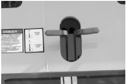
3. Using the counterweight removal control valve levers (Figure4-12), raise the counterweight cylinders to relieve weight on the counterweight pin assemblies (the ones holding the removable counterweight to the superstructure).
4. Remove the two counterweight pin assemblies from the superstructure frame lugs and the counterweight. To remove each pin assembly, push it in and turn it so its roll pin disengages from the related catch on the counterweight. (See Figure4-13.)
5. Stow the counterweight pin assemblies in the bushings on the side of the superstructure.
6. Using the counterweight removal control levers, slowly lower the counterweight onto the support weldment. Make sure the counterweight’s weight fully rests on the support weldment.
7. Remove the two cylinder pin assemblies from the counterweight lugs and cylinder clevises. Raise the cylinders and stow the cylinder pin assemblies in the cylinder clevises; secure the pin assemblies with their cotter pins.
Danger
Travel is not permitted with the removable counterweight on the carrier deck.
8. Remove counterweight from the support weldment before moving crane.
9. Using the crane’s boom and hoist or other crane, lift counterweight from the carrier deck to the auxiliary transport vehicle.
ItemDescription
1Control Valve Levers
2Counterweight Cylinders
3Counterweight Pin Assemblies
4Cylinder Pin Assemblies
5Removable Counterweight
6Leveling Bolts (4 places)
7Counterweight Lifting Lugs (4 places)
8Hoist(s)
9Superstructure
Installation
1. Position the crane on a firm level surface. Fully extend and set the outriggers.
2. Select the proper without counterweight operating code on the LMI.
NOTE: The counterweight weighs about 6033 kg (13,270 pounds).
3. Using the crane’s boom and hoist or other crane, lift counterweight from the auxiliary transport vehicle and position the counterweight on the support weldment on the front outrigger box.
4. Rotate and align the rear of the superstructure above the removable counterweight sitting on the support weld. Engaging the swing lock pin will aid alignment.
5. Using the counterweight removal control valve levers located on either side of the turntable, lower the counterweight cylinders. Pin the cylinders to the