6 minute read
OPERATING CONTROLS AND PROCEDURESRT540E
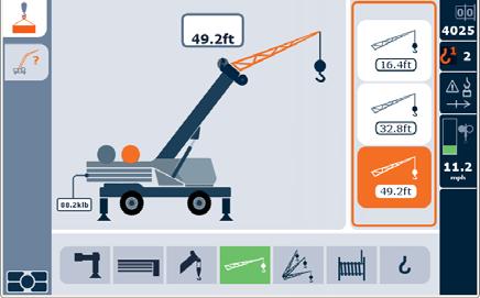
Set the Boom
Turn jog dial clockwise to set boom, including aux nose and reeving options.
NOTE: If no jib configuration is chosen for the boom, the following selection will be for reeving.
Set the Jib Length (if installed)
Turn jog dial clockwise and select to determine and choose the length of the jib, including inserts.
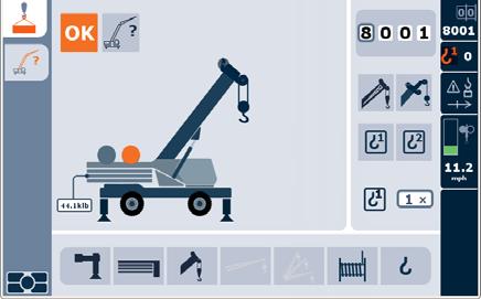
Hoist Selection
Turn jog dial clockwise to select between the main and optional auxiliary hoists.


Set the Jib Angle (if installed)
Turn jog dial clockwise to program the jib angle after the length is selected.
Reeving Selection

Turn jog dial clockwise to select the icon for reeving options. Press ENTER a second time and turn dial to change reeving number options.
Switch to RCL Home Screen Display
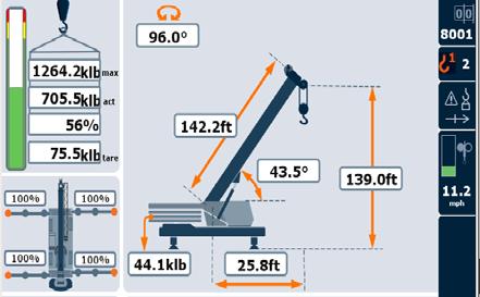
Press Screen Toggle button (4) (Figure3-13) on the Jog Dial menu control to switch to the RCL main menu screen.
Press ENTER button on Jog Dial to choose and set the desired reeving option and move on to the next screen.

Press ENTER on Jog Dial or Menu button to access RCL Main Screen. This screen appears after the key is turned on, but the operator must press the tab button to display the tare value.

Grove
Foot Pedal Controls
applied to the brake release circuit and applies the spring brake according to the pressure from the swing power brake valve.
Telescope Control Pedal (Optional)
The Telescope Control Pedal (4) (Figure3-16) is supplied when the crane is equipped with an auxiliary hoist, is located in the middle of the cab floor. Pushing forward on the top of the pedal will extend the boom and pushing down on the bottom of the pedal will retract the boom.
Service Brake Pedal
The Service Brake Pedal (5) (Figure3-16) is the second pedal from the right on the cab floor. Depressing the pedal controls the application of the service brakes.

Foot Throttle Pedal
The Foot Throttle Pedal (6) (Figure3-16) is located on the right side of the floor. It is used to control engine RPM which increases or decreases proportionately with the amount of foot pressure applied to the pedal. The pedal is electrically connected to the superstructure control module which sends the signal to the engine ECM via the J1939 data link.
ItemDescription
1360° Swing Lock Pedal
2360° Swing Lock Release Lever
3Swing Brake Pedal
4Telescope Control Foot Pedal (Optional)
5Service Brake Pedal
6Foot Throttle Pedal
360° Swing Lock Pedal
The 360° Swing Lock Pedal (1) (Figure3-16) is located on the left side of the crane cab floor. The pedal is used to activate the swing lock to prevent the superstructure from turning. To release the swing lock, pull up on the 360° Swing Lock Release Lever (2).
Swing Brake Pedal
The Swing Brake Pedal (3) (Figure3-16) is located on the left side of the cab floor. The swing brake pedal is used to actuate the swing brake to slow or stop swing motion. Braking is proportional to pedal depression. With the pedal not depressed and the swing brake control valve disengaged, hydraulic pressure is applied to the brake, overcoming spring pressure and releasing the brake. Depressing the pedal actuates a swing power brake valve to apply pressure to the brake assembly. This pressure aids the spring pressure to overcome the hydraulic pressure being
Miscellaneous Controls And Indicators
Fuse Panel
The fuse panel (1) (Figure3-17) is located behind the cab seat on the cab fuse and relay panel assembly. It contains up to 20 fuses that protect the various electrical components of the crane.
Buzzer
The buzzer in the display sounds when the following conditions exist:
• Engine Alarms
• Emergency Stop Switch activated
• Low brake pressure
• High hydraulic oil temperature
• High transmission oil temperature
• Low steer pressure condition (for CE units)
• Hoist third wrap condition (for CE units)
• Anti Two-Block alarm
• Engine compartment protection program
RCL Emergency Override Switch (Non-CE Certified Cranes)
RCL Emergency Override Switch and Indicator (CE Certified Cranes)

Warning
Loss of RCL Monitoring Hazard!
The RCL Emergency Override switch is to be used in emergency situations only.
Do not operate the crane with the RCL overridden during normal operations.
When the RCL is overridden always have a helper on the ground to signal you.
The RCL system, when programmed accurately, will lockout nearly every crane function—boom up/down, telescope extend/retract, hoist up and swing left/right—when a lift is attempted at or above the crane's capacity or when a twoblock condition exists. Only the particular function(s) that cause the existing lockout condition are blocked. Locking out these functions prevents the overload or two-block condition from worsening.
The RCL emergency override switch (2) (Figure3-17) is a key operated switch that is located inside the operator cab on the panel assembly behind the seat. When actuated (turned clockwise), the switch will override and prevent the RCL from locking out craning functions (Third Wrap Limit and Anti Two-Block) should an overload condition occur. Turn the key counterclockwise to bypass the Anti Two-Block Switch, Telescope extend/retract, 3rd Wrap Indicator (hoist lowering limit) and Boom up/down.
Overriding the RCL with this switch should only be done in the case of an emergency or when servicing the boom.
A flashing light on the RCL display indicates the switch has been activated.
Warning
Loss of RCL Monitoring Hazard!
The RCL Emergency Override Switch is to be used in emergency situations only.
Do not operate the crane with the RCL overridden during normal operations.
When the RCL is overridden, always have a helper on the ground to signal you.
The RCL system, when programmed accurately, will lockout nearly every crane function—boom up/down, telescope extend/retract, hoist up and swing left/right—when a lift is attempted at or above the crane's capacity or when a twoblock condition exists. Only the particular function(s) that cause the existing lockout condition are blocked. Locking out these functions prevents the overload or two-block condition from worsening.
The RCL emergency override switch is located inside a keylocked single-door enclosure (1) (Figure3-18) that is attached to the outside rear of the operator's cab. The switch is a two-position momentary rocker switch that, when actuated, will override and prevent the RCL, for a period of 30 minutes, from locking out craning functions (boom down, telescope extend, third wrap limit and hoist up) should an overload condition occur.
The other RCL emergency override switch (19) (Figure3-6) is a key operated switch that is located inside the operator cab below the CCS screen, in front of the Emergency Stop Switch. When actuated (turned clockwise), the switch will override and prevent the RCL from locking out craning functions (Third Wrap Limit and Anti Two-Block) should an overload condition occur. Turn the key counterclockwise to bypass the Anti Two-Block Switch, Telescope extend/retract, 3rd Wrap Indicator (hoist lowering limit) and Boom up/down.
Overriding the RCL with this switch should only be done in the case of an emergency or when servicing the boom.
Upon activation, all craning function movements are reduced to 15% of their normal maximum speeds.
The RCL override function is automatically cancelled after 30 minutes. The RCL override function can also be cancelled by the operator by either pressing the RCL emergency override switch a second time or by turning off the engine. However, turning off crane functions does not disable the RCL override.
NOTE: Before powering up crane, ensure that the RCL Override Switch is in the Normal (not Override) position to avoid an error code.
RCL Internal Light Bar (Optional)
The Rated Capacity Limiter (RCL) Internal Light Bar is located on the upper left hand corner of the crane cab. The RCL is an operational aid that warns a crane operator of approaching overload conditions and other conditions that could cause damage to equipment and personnel.
Strobe Light or Beacon (Optional) (Not Shown)
The strobe light or beacon is on the right side of the superstructure. It is on when the ignition switch is on.
Backup Alarm (Not Shown)
The backup alarm is an audio system used to warn personnel outside the crane when the crane is backing up. The alarm system is electrical and consists of the backup alarm and its associated wiring. The alarm is connected to the electrical wiring for the transmission reverse solenoids. It is activated when the transmission shifter is in the reverse position. The backup alarm is installed in the rear outrigger box behind the grill plate.
Emergency Exit
The windshield is considered the Emergency Exit. In an emergency, push out on the windshield and escape through the opening.

Appendix A: Crane Control System (CCS) Symbols and Icons
Symbol
Description
3rd Wrap Warning
4-Wheel Drive
Auxiliary Hoist Status
Auxiliary Hoist Disabled
Auxiliary Hoist Enabled
Auxiliary Hoist Raise
Auxiliary Hoist Not In Use
Auxiliary Hoist Lower
Battery Voltage
Boom Lift Status
Boom No Load Chart
Bypass 1 Active
Bypass 2 Active
Bypass 3 Active
Bypass 1 Pressed
Bypass 2 Pressed
GROVE


