33 minute read
OPERATING CONTROLS AND PROCEDURESRT540E


Cold Weather Operation
The following recommendations are for operating Grove cranes in very low (i.e. freezing) temperatures.
Use particular care to ensure that cranes being operated in very cold temperatures are operated and maintained in accordance with the procedures as provided by Manitowoc Crane Care. Cranes should have appropriate hydraulic oil, lubricants, and other auxiliary items required for operation in sub-zero temperatures. Individual crane functions should be operated to ensure they are sufficiently warmed prior to performing a lift.
Operation of cranes at full rated capacities in temperatures between 0°C and -40°C (+32°F and -40°F) or lower shall be accomplished only by competent operators who possess the skill, experience, and dexterity to ensure smooth operation. Shock loading shall be avoided. See Section 5 of this manual for more detailed information on operation of cranes down to -40°F.
Operation Below -40°C (-40°F)
For crane operation below -40°C (-40°F), capacities shall be derated 3.67% of the capacities shown on the load chart for each 1°C below -40°C (1.8°F below -40°F).
Warm-up Procedures
1. Engage the parking brake and apply the service brake.
2. Shift the transmission into the highest gear and increase the engine RPM to 1500 for 15 seconds, then allow the engine RPM to return to idle.
3. Repeat Step 2 until the temperature of the transmission sump reaches normal operating temperature.
Alternate Warm-up Procedures
1. Setup crane on outriggers.
2. Engage the transmission with 4-wheel drive selected (if equipped) and allow crane to run at idle until the temperature of the transmission sump reaches normal operating temperature.
NOTE: Warm-up operation of 4-wheel drive transmission engaged in 2-wheel drive only could cause transmission damage.
Hoist
Performing a warm-up procedure is recommended at every startup and is required at ambient temperatures below 4°C (40°F).
Warm-up Procedures:
1. Without operating the hoist function, warm the hydraulic oil (see Hydraulic Oil System, page 3-2).
2. Once the hydraulic system is warm, operate the unloaded hoist, in both directions, at low speeds several times to prime all hydraulic lines with warm hydraulic oil and to circulate gear lubricant through the planetary gear sets.
Swing Drive and Turntable Bearing
Warm-up Procedures for Temperatures Above -7°C (20°F)
1. Setup the crane on fully extended outriggers, with the boom fully retracted and near maximum lift angle with no load applied.
2. Rotate the superstructure at a speed of less than one RPM for at least one complete revolution in one direction, then rotate the superstructure at a speed of less than one RPM for at least one complete revolution in the opposite direction.
Warm-up Procedures for Temperatures Below -7°C (20°F)
1. Ensure the boom is fully retracted and near maximum lift angle with no load applied.
2. Rotate the superstructure at a speed of less than onehalf RPM for at least two complete revolutions in one direction, then rotate the superstructure at a speed of less than one-half RPM for at least two complete revolutions in the opposite direction.
Axles
Warm-up Procedures for Temperatures Below -35°C (-30°F)
1. Setup the crane on outriggers.
2. Engage the transmission (see Transmission, page 3-1) with 4-wheel drive selected (if equipped) and allow crane to run at idle until the temperature of the transmission sump reaches normal operating temperature.
NOTE: Warm-up operation of 4-wheel drive transmission engaged in 2-wheel drive only could cause transmission damage.
Hydraulic Oil System
Operating Limits and Warm-up Procedures
•From 4°C to -10°C (40°F to 15°F): Crane operation without a load is allowed with medium engine RPM and medium function speed (joystick position) until the fluid reaches at least 10°C (50°F). It is then recommended that all crane functions be cycled to remove cold fluid from all components and cylinders of the hydraulic system. If there is any unusual sound coming from the crane’s hydraulic pumps or motors, stop the operation and engine immediately and contact a Manitowoc distributor.
•From 10°C to 4°C (50°F to 40°F): Crane operation with a load is allowed with medium engine RPM and medium function speed (joystick position) until the fluid reaches at least 10°C (50°F).
•From 95°C to 10°C (200°F to 50°F): Crane operation with a load is allowed with no restrictions.
•Above 95°C (200°F): No crane operation is allowed. Let the crane’s hydraulic oil cool by running the engine at idle with no functions actuated.
Engine Operation
Start-up and shutdown procedures for most diesel engines are generally the same. Therefore, the following procedures can be applied, except where specific differences are noted. (Refer to the applicable engine manufacturer’s manual for detailed procedures).
Start-Up Procedure
Make an under-the-hood inspection for fuel, oil, and coolant leaks, worn drive belts, and trash build-up.
Danger
Diesel engine exhaust can be harmful to your health. Only operate the engine in a well ventilated area or vent exhaust outside.
Caution
Never crank engine for more than 30 seconds during an attempted start. If engine does not start after 30 seconds, allow starter motor to cool for two minutes before attempting another start.
Caution
If engine does not start after four attempts, correct malfunction before attempting another start.
Use the correct grade of oil for the prevailing temperature in the crankcase to prevent hard cranking. Diesel fuel should have a pour point of 5°C (10°F) less than the lowest expected temperature. In case of an emergency, white kerosene can be added to the fuel to bring the pour point down to the required temperature. This will prevent clogging of filters and small passages by wax crystals. The addition of kerosene is NOT recommended for general use.
Ensure Battery Disconnect Switch handle (1) (Figure3-7) is in the ON position (handle shown in the OFF position)
Cold Engine
The engine warning and engine stop indicators will illuminate and go off in sequence after about two seconds (as a check) when the key is first turned on. If an indicator comes on and continues to blink after initial start-up, there is a problem that needs to be corrected. If the engine warning icon is selected, a screen will open listing the engine error codes.
An engine block heater and grid heater are provided to aid in cold-starting.
1. Ensure the emergency stop switch is not pressed.
2. Set the parking brake to ON and position the transmission shift lever to neutral.
NOTE: The engine will not crank unless the transmission shift lever is in neutral.
NOTE: The engine “wait to start” indicator located on the top left side of the front console illuminates amber for a period of time when the ignition is turned to the on position. The engine should not be cranked until the indicator turns off.
3. Turn the key to the first position. The CCS screen will provide data for the various engine systems and alert the operator to any detected fault codes. Sound the horn (left of steering wheel) once.
GROVE
4. Turn the ignition switch to start (far right position) and release immediately when the engine starts. Do not push or hold the throttle down. The ECM will automatically provide the proper amount of fuel to start the engine.

Caution
If oil pressure and/or temperature indicator(s) do not display the proper readings, shut down engine and correct malfunction.
5. Allow the engine to warm up for about five minutes before applying a load. Do not race the engine for a faster warm up.
Idling The Engine
Idling the engine unnecessarily for long periods of time wastes fuel and fouls injector nozzles. Unburned fuel causes carbon formation; oil dilution; formation of lacquer or gummy deposits on the valves, pistons and rings; and rapid accumulation of sludge in the engine.
NOTE: When prolonged engine idling is necessary, maintain at least 800 rpm.
Racing The Engine
DO NOT race the engine du ring the warm-up period or operate the engine beyond governed speed (as might occur in downhill operation or dow nshifting). Engine bearings, pistons, and valves may be damaged if these precautions are not taken.
Shutdown Procedure
1. Allow the engine to run at fast idle speed for about five minutes to avoid high internal heat rise and allow for heat dissipation.
2. Position the ignition switch to off (vertical position).
3. Drain the fuel filter-water separator.
Battery Disconnect
The battery disconnect switch is located in the battery box on the left side of the crane. To disconnect the batteries, turn the battery disconnect switch to OFF. Turn the switch to ON to connect the batteries.
Crane Travel Operation Seat Belts
1. Before fastening a seat belt, always adjust the driver’s seat to the position in which you will drive.
2. Pull the belt across your lap and push the latch plate into the buckle until it clicks (Figure 3-8).
3. To reduce the risk of sliding under the belt during a collision, position the belt across your lap as low on your hips as possible and pull it toward the door to a snug fit.
Traveling — General
Warning
Inadvertent Operation Hazard!
Before traveling, ensure that the crane functions are fully disabled. The crane function enable switch is a spring return switch and cannot be put in a specific OFF position.This will prevent inadvertent operation of craning functions due to bumping of the controllers while traveling.
RT machines are subject to the same road regulations as any truck, regarding gross weight, width, and length limitations.
Although RT machines are specifically designed for rough terrain, the operator should be extremely cautious and aware of the terrain in which he is operating.
Warning
Tipping Hazard!
Avoid holes, rocks, extremely soft surfaces, and any other obstacles which might subject the crane to undue stresses or possible overturn.
Do not drive the crane with the boom off center because automatic oscillation lockout will occur, making the crane subject to tipping on uneven surfaces. Center the boom over the front, disable swing functions and engage the Turntable Lock Pin (if equipped).
Fully retract the boom and ensure the swingaway jib is properly stowed and secured.
Caution
Machine Damage Hazard!
Do not travel with an empty hook in a position where it can swing freely (except where noted). Either remove the hook block and/or headache ball from the hoist cable(s) and stow securely or make sure the hook block or headache ball is properly secured to the tie down provided for that purpose.
Do not drive the crane with the lift cylinder bottomed. At a minimum, position the boom slightly above horizontal. Fully retract the outrigger jacks and properly store the floats.
Disengage the pumps (if applicable) for extended traveling.
Use four-wheel drive only when greater traction is necessary. (Refer to Four-Wheel Drive Operation , page 3-17 for operating instructions.)
Caution
Machine Damage Hazard!
On open ground, tow or pull only on the tow/tie-down lugs or with the optional pintle hook.
Do not tow or pull in 1st gear with the Drive Axle Selector Switch in two-wheel drive position. Severe damage to the drive train will result. Always engage four-wheel drive. Should the crane become mired down, use a tow truck or tractor to free the vehicle. Severe damage to the transmission or axles may occur if the operator attempts to free the crane unassisted.
There are two tow/tie-down lugs installed on each end of the crane. Use both lugs to tow or pull the crane.
Ensure the outrigger beams and jacks are fully retracted with the floats properly stowed.
Traveling on Slopes
Crane operators need to exercise caution whenever operating the crane on uneven surfaces. Travel on slopes is permitted as long as the following conditions are met.
• Do not exceed a 15% (8.5°) slope side-to-side or foreand-aft.
• Travel must be on an improved surface or on hardpacked dry earth having a minimum 0.5 coefficient of adhesion.
• Limit travel to a forward direction only.
• Do not exceed a speed of 1.6km/h (1mph).
• Fully retract all boom sections.
• Stow or remove the boom extension from the crane.
• Lower the boom to horizontal and position over the front of the crane.
• Engage the swing brake and turntable lock pin.
• Either the hook block may be reeved over the main boom nose or the headache ball may be reeved over the main boom nose or auxiliary boom nose; the other must be removed. If the hook block or headache ball remains reeved on the boom, it must be secured at the tie down on the carrier to prevent swinging.
• Inflate tires to the recommended pressure for pick and carry operations.
• Ensure the hydraulic tank is filled to the specified level. Ensure the fuel tank is over half full.
• Do not support any loads by the boom (i.e., no pick and carry loads) while traversing a slope.
• Remove all cribbing or other non-standard accessories from the crane.
• Avoid holes, rocks, extremely soft surfaces, and any other obstacles that might subject the crane to undue stresses and possible overturn.
• Conduct all travel with the assistance of a ground person to warn the operator of any changing conditions in the terrain being traversed.
The owner/lessee must take appropriate measures to ensure that all persons operating or working with the affected models are in compliance with The Manitowoc Company, Inc. recommendations. The operator of the crane assumes responsibility for determining the suitability of traveling on a slope. Traveling on a slope should only be attempted under the controlled conditions specified in these guidelines, and must be conducted with the utmost diligence and care to ensure the safety of all personnel performing the operation and/or working around the crane.
Should the operator need to traverse slopes outside the criteria defined in the above guidelines contact the The Manitowoc Company, Inc. for further guidance.
Traveling with Elevated Boom
Warning
Overhead Objects Hazard
Contacting overhead objects while driving the crane may result in death, severe injury, and/or equipment damage. Traveling with the boom elevated should only be attempted under the controlled conditions specified in this section.
Exercise caution whenever driving the crane with the boom elevated. Travel with the boom elevated is permitted as long as the following steps are followed.
• Limit travel to firm, level surfaces.
• Inspect the route of travel prior to moving the crane. Pay particular attention to any changing conditions in the terrain being traversed. Also, avoid any overhead obstructions.
• Travel must be performed in a controlled fashion.
• Do not exceed a speed of 24km/h (15mph).
• Inflate tires to the recommended pressure for travel operations.
• When using the towing attachments, the boom must remain horizontal.
• Fully retract all boom sections.
• Refer to Traveling with Boom Extension Erected, page 3-15 if the boom extension is in the erected position.
• Position the boom over the front of the crane.
• Engage the swing brake and turntable lock pin.
• The hook block may be reeved over the main boom nose. The headache ball may be reeved over the main boom nose or auxiliary boom nose. The block and ball may be suspended below the boom nose. It is also acceptable to secure the block or the ball to the tie down point on the carrier to prevent swinging if necessary.
• Limit boom angle to a maximum of 20°.
• Do not support any load from the boom (see Pick and Carry Load chart for limitations for this application).
• Remove all cribbing or other non-standard accessories from the crane.
• Avoid holes, rocks, extremely soft surfaces and any other obstacles that might subject the crane to undue stresses and possible overturn.
• Ensure adequate clearance to any overhead obstructions that the crane may be required to travel beneath.
• Ensure that all personnel involved in the operation and those working around the crane are aware of any hazards that may be encountered and are trained about how to avoid the hazards.
Traveling with Boom Extension Erected 7.9m (26ft) Boom Extension
Follow the steps below when traveling with the 7.9m (26ft) extension erected.
• Position the 7.9m (26ft) boom extension at minimum offset. Pin the 5.8m (19ft) extension in the fully retracted position.
• Travel only on a firm, level surface.
• Fully retract the main boom.
• Limit main boom angle to a minimum of 0° and a maximum of 30°.
• Do not exceed a speed of 2.7km/h (1.7mph) and ensure crane is in low range, first gear.
• Ensure main counterweight is installed.
• Position the boom over the front of the crane.
• Engage the swing brake and turntable lock pin.
• Remove hookblock from main boom nose.
• Headache ball may be reeved over boom extension, hanging 0.9m (3ft) below sheave.
13.7m (45ft) Boom Extension
Travel with the 13.7m (45ft) boom extension erected is not permitted.
Extended Travel
Depending upon the tire manufacturer, the higher inflation pressures normally specified for lifting on rubber are not recommended for site to site transfer over extended distances. The higher static/creep 8km/h (5mph) inflation pressures may remain in the tire while operating the crane on site within a distance of less than 6.4km (4mi).
Caution
Tire Damage!
For extended travel, check the cold tire pressure prior to start. (Refer to tire inflation chart in Load Chart Book.) After every one hour of travel time, regardless of ambient temperature, stop and allow the tires to cool off for at least 30 minutes. At the destination, the tires must be allowed to cool to ambient temperature before crane lifting on rubber.
Traveling — Forward
CAUTION
Machine Damage!
Engage the turntable lock pin for extended travel. Failure to engage the lock pin may allow the superstructure to swing uncontrolled, damaging the machine and/or property.
1. With the Transmission Shift Lever in the neutral (N) position, start the engine and allow it to adequately warm up.
2. Depress the Service Brake Foot Pedal.
Warning
Run-away Crane!
Releasing the parking brake while the low service brake pressure indicator is illuminated and the buzzer is sounding, indicating the service brakes are inoperable, may result in the crane rolling away freely without the ability of the operator to stop the crane.
Never release the parking brake while the low service brake pressure indicator is illuminated and the buzzer is sounding.
4. Position the Drive Axle Switch to either two-wheel high or four-wheel low.
Caution
Use four-wheel drive only when more traction is required.
5. Lift the Transmission Shift Lever up out of its detent and push the lever to the forward (F) position, then rotate the Transmission Shift Lever Knob to the first (1) gear position. The gear selection “F1” will appear in the CCS Display to indicate that forward propulsion and first (1) gear have been selected; if the Service Brake Foot Pedal is not depressed prior to shifting to a gear, the gear selection will flash in the CCS Display until the Transmission Shift Lever is returned to the neutral (N) position, and the transmission will not shift.
6. Release the Service Brake Foot Pedal and depress the Foot Throttle Pedal until maximum first gear speed is attained, then rotate the Transmission Shift Lever Knob to the second (II) gear position to continue to increase speed. For additional speed, continue shifting to a higher gear.
Caution
Possible Machine Damage!
Do not downshift to a lower gear if the road speed is greater than the maximum speed of the lower gear.
Traveling — Reverse
Traveling in reverse is accomplished the same way as traveling forward, except for shifting the Transmission Shift Lever to reverse (R). Refer to Traveling — Forward, page 316.
Caution
Possible Machine Damage!
Apply service brakes and bring crane to a complete stop before shifting transmission into reverse.
Steering
Steering is accomplished by the steering wheel and the rear steer control. These controls, used singly or together, provide front wheel steering, rear wheel steering, four-wheel steering, and crabbing capabilities (Figure3-9).
Front Wheel Steering
Conventional front wheel steering is accomplished with the steering wheel. This method of steering should always be used when traveling at higher speeds.
Four-Wheel Drive Operation
Warning
Unexpected Operation Hazard!
Operate the rear steer ONLY at slow speeds for added job site maneuverability.
Rear Wheel Steering
Rear wheel steering is controll ed by the Rear Steer Control Switch. Moving the control switch to the desired position activates the rear steer cylinders, thereby steering the crane in the selected direction.
Four Wheel Steering
Four wheel steering is accomplished with the steering wheel and the Rear Steer Control Switch. Depending upon which direction the operator wishes to travel, the steering wheel is turned opposite direction of the Rear Steer control position. This allows the crane to turn or maneuver in close, restricted areas.
Crabbing
Crabbing is accomplished with the steering wheel and the Rear Steer Control Switch. Depending upon which direction the operator wishes to travel (crab), the steering wheel is turned in the same direction as the Rear Steer Control Switch. This permits driving the crane forward or backward in a crabbing manner.
Caution
Machine Damage Hazard!
Do not tow or pull in 1st gear with the Drive Axle Selector Switch in two-wheel drive position. Severe damage to the drive train will result. Always engage four-wheel drive.
If more traction is required due to slipping or spinning wheels, engage the front axle drive as follows:
Caution
Possible Machine Damage!
Before shifting from two-wheel drive to four-wheel drive (or from four back to two), crane travel must be stopped.
1. Stop the crane by depressing the Service Brake Foot Pedal.
2. Position the Transmission Shift Lever to the neutral (N) position.
3. Position the Drive Axle Selector Switch to four-wheel low.
NOTE: If the Drive Axle Selector Switch is positioned to four-wheel low and the Service Brake Foot Pedal is not depressed and the Transmission Shift Lever is not in neutral (N) position, the Four-Wheel Drive Indicator will flash and the four-wheel drive function will not engage.
4. Select gear speed and direction of travel using the Transmission Shift Lever and Knob.
5. Drive the crane as described under Traveling — Forward, page 3-16.
6. Return the Drive Axle Selector Switch to the two-wheel high position as soon as two-wheel traction will suffice and crane motion has stopped; again, the Service Brake Foot Pedal must be depressed and the Transmission Shift Lever must be in the neutral (N) position to shift from four-wheel low to two-wheel high.
Differential Lock Operation (Optional)
Caution
Unexpected Operation!
When using the differential lock, steering characteristics may be affected.
Try to use four-wheel drive to gain adequate traction before using the differential lock.
Do not operate the differential lock when traveling downhill; at speeds above 16.1km/h (10mph); on hard, dry surfaces; and/or during axle spin-out.
NOTE: The differential lock will not operate unless the Drive Selector Switch is in the four-wheel low position.
General
The purpose of the differential lock is to provide maximum traction and control on poor road or highway surfaces. When the differential locks are actuated, the clutch collar completely locks the differential case, gearing, and axle shafts together, thus maximizing traction to both wheels of each axle. The lock position will also protect against spinout. When normal driving conditions exist (during periods of good traction), the differential locks should not be actuated. The axles should be allowed to op erate with differential action between both wheels.
Follow the steps below when engaging/disengaging the differential lock function.
1. Lock the differentials by pressing and holding the Axle Differential Control Switch in the lock position; disengage the function by releasing the switch.
2. Lock/unlock the differentials only when the vehicle is standing still or moving at a constant low speed with the wheels not slipping.
Caution
Possible Machine Damage!
When driving on hard, dry surfaces with the differentials locked, do not turn the wheels. Damage to the drive line components can result.
Do not lock the differentials when the wheels are slipping. Damage to the differentials can result.
3. Locked differentials cause the crane’s turning radius to increase, creating an understeer condition; use caution, good judgement and drive at low speeds when operating the vehicle with lock differentials.
4. Lock the differentials only when maximum traction is needed on poor road or highway surfaces.
Caution
Possible Loss of Vehicle Stability!
Do not lock the differentials when the vehicle is traveling down steep grades and traction is minimal.
5. Always unlock the differentials when the need for maximum traction has passed or when traveling on good road or highway surfaces.
Operation
The differential lock function should preferably be engaged when the crane is stationary but may be engaged when moving, if the following conditions are met:
1. The crane is moving very slowly (creep speed).
2. The wheels are not spinning at the time of engagement. When traveling with the differentials locked, do not deviate from a straight path more than is absolutely necessary. Engage the differential locks by doing the following:
1. Position the Axle Differential Lock Control Switch to the locked position with the crane stationary or moving at a slow speed.
If moving at a slow speed, let up momentarily on the Foot Throttle Pedal to relieve torque on the differential gearing. This will fully engage the differential locks.
NOTE: When the differentials are locked, the Axle Differential Locked Indicator illuminates.
2. Proceed over the poor road condition cautiously. When the adverse condition has passed, disengage the differential locks by doing the following:
1. Release the Axle Differential Lock Control Switch, allowing it to return to the unlocked position while maintaining a slow speed.
2. Let up momentarily on the Foot Throttle Pedal to relieve torque on the differential gearing, allowing the differential to fully unlock.
NOTE: When the differentials are unlocked, the Axle Differential Locked Indicator will not be illuminated.
3. Resume driving at a normal speed using good driving judgement.
Axle Oscillation Lockouts Operation
The following procedure should be used to periodically check the axle oscillation system and ensure that it is in proper working condition.
1. Ensure the tires are inflated to the recommended pressure. Refer to the Load Chart Book in the crane cab for proper inflation pressures.
2. With the hook unloaded, the boom fully retracted and centered over the front at no more than a 10° to 15° boom angle, position the crane on a block or curb so that one rear tire is approximately 6 to 12in (15 to 30cm) above the level of the opposite tire.
3. Slowly swing the superstructure to the left or right until the axle oscillation lockout valve is activated. This will lock the rear axle out of level. Do not swing beyond the tire track.
4. After engaging the swing brake, slowly drive off of the block or curb and stop. The rear tires should both be touching the road surface and the opposite front tire should be light or slightly off the road surface.
5. Release the swing brake and swing the superstructure until it is centered over the front.
DANGER Tipping Hazard!
Do not operate the crane if the axle oscillation lockout system is not functioning properly.
Failure to comply with this warning may result in death or serious injury.
If the axle oscillation lockout valve is functioning properly, the crane will re-level itself; if the valve is not working properly, the crane will not re-level itself. If the rear axle does not lock or unlock properly, evaluate the lockout system and repair as necessary.
General Crane Operation Pump Drive
The main #1 hydraulic pump is driven by a transmission PTO. The #2 hydraulic pump is mounted to the rear of pump #1 and is direct engine driven.
Control Lever Operation
The control lever operation for crane functions is proportional, i.e., the closer the lever is to neutral (center), the slower the system responds. Return the control lever to neutral to hold the load. Do not feather the hoist control to hold the load.
NOTE: Always operate the control levers with slow, even pressure.
Preload Check
After the crane has been readied for service, an operational check of all crane functions (with no load applied) should be performed. Preload check is as follows:
• Extend and set the outriggers and level the crane.
• Raise, lower, and swing the boom right and left at least 45 degrees.
• Telescope the boom out and back in, ensuring all sections extend and retract properly.
• Raise and lower the cable a few times at various boom lengths. Make sure there are no kinks and that the cable is spooling on the hoist properly.
Caution
Run the engine at or near the governed RPM during operation of all crane functions.
NOTE: Carefully read and become familiar with all crane operating instructions before operating the crane.
Using Your Load Chart
NOTE: One of the most important tools of every Grove crane is the load chart found in the crane operator's cab.
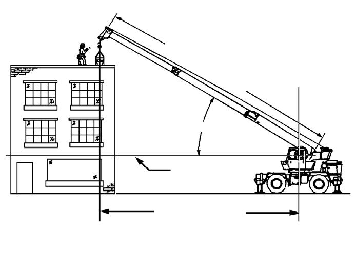
NOTE: Refer to (Figure 3-10) for terms to know in determining lifting capacities.
The load chart contains the lifting capacities of the crane in all allowable lifting configurations, and must be thoroughly understood by the operator.
The load chart is divided into capabilities limited by crane structural strength and stability which is shown by a bold line across the chart. Structural strength limits are above the line and stability limits are below the line.
The left column is the load radius, which is the distance from the axis of the crane rotation to the load center of gravity. The top row lists various boom lengths from fully retracted to fully extended (with swingaway extension). The number at the intersection of the left column and top row is the total load limit for that load radius a nd boom length. The number in parentheses below the total load limit is the required boom angle (in degrees) for that load. The lower weight limit for the 2 boom lengths should be used.
Another important section is the range diagram. The range diagram shows the operating radius and tip height that can be achieved at a given boom length and angle. If the operator knows the radius a nd tip height required for a specific lift, the angle and boom length can quickly be determined from the range diagram. Or if he knows the boom length and angle, he can quickly determine the tip height and operating radius.
A lifting diagram is included for over-side, over-rear, and over-front lifting areas. The lifting area diagram shows that the locations of the outrigger jack cylinders in the full extended position are used to mark the boundaries of the lifting areas.
Another section contains notes for lifting capacities. Be sure to read and understand all notes concerning lifting capacities.
The load chart also gives weight reductions for Manitowoc/ Grove load handling devices such as hookblocks, overhaul balls, boom extension sections, etc., which must be considered as part of the load. The weight of any other load handling devices such as chains, slings, or spreader bars must also be added to the weight of the load.
NOTE: The information in the following paragraph is an example of how to compute a lift. The numbers used in the example may not coincide with the load chart in the crane cab.
Problem: A concrete beam weighing 2268kg (5000lb) needs to be lifted to a height of 9.1m (30ft) at a radius of 15.2m (50ft) (maximum). The range diagram indicates the boom must be extended to 18.9m (62ft) in order to reach a height of 9.1m (30ft) at a radius of 15.2m (50ft).
First we need to check the crane for load handling devices. In our example, the crane is equipped with a auxiliary boom nose (rooster sheave) and a five ton overhaul ball. The rooster sheave is 50kg (110lb), and the overhaul ball is 78kg (172lb) for a total of 128kg (282lb). The lift requires slings and spreader bars weighing 159kg (350lb) which makes the total weight for the load handling devices 286kg (632lb).
A check of the load chart for a 15.2m (50ft) radius and 19.5m (64ft) of boom length shows a capacity of 3601kg (7940lb) on outriggers over-front and 4970lb on outriggers 360 degrees. We subtract the load handling weight of 632lb from the load capacity of 3601kg (7940lb) and 2254kg (4970lb). The result is a weight capacity of 3315kg (7308lb) over-the-front and 1968kg (4338lb) for 360 degrees. We are constricted in making the lift over-front only and the boom angle will be about 29 degrees.
Proper Leveling of the Crane
ASME B30.5 specifies that if a crane is not level within 1% of grade, the allowable capacities must be reduced. Therefore, whether lifting on rubber or outriggers, it is essential that the crane is level to within 1% of grade. The bubble level that is provided on the crane is calibrated to be accurate within 1% of grade.
To properly level the crane, the boom must be positioned over the front of the crane, fully lowered to horizontal and fully retracted (for cranes fitted with a boom rest, the boom shall be stowed onto the rest). Raise and level the crane using the outriggers; refer to The crane also allows operations with the outriggers fully retracted., page 3-21.
A working crane may settle during lifting operations. Frequently check the crane for level. When rechecking the crane for level, the boom must be positioned over the front of the crane, fully lowered to horizontal and fully retracted (for cranes fitted with a boom rest, the boom shall be stowed onto the rest). If necessary, relevel the crane using the procedures under The crane also allows operations with the outriggers fully retracted., page 3-21.
Level Indicator Adjustment
The Level Indicator should be checked periodically; if it is suspected that the Level Indicator is out of adjustment, verify and adjust the level as follows:
1. Position the crane on a firm, level surface.
2. Extend and set the outriggers. Level the crane, as indicated by the level indicator, using the outriggers.
3. Place a miracle pointer level, carpenter level, or similar type device on a machined surface such as the turntable bearing or bearing mounting surfaces.
4. Using the outriggers, level the crane as indicated on the leveling device used in step 3.
5. Using the level indicator mounting screws, adjust the level indicator to show level.
Crane Functions
Using the Outriggers
The outriggers are operated from the front console in the cab, or by using the jog dial on the armrest.
Danger
To prevent serious injury or death, keep clear of moving outrigger beams/jacks.
Danger
Death or serious injury could result from improper crane setup on outriggers.
Warning
Be sure the outriggers are properly extended and set, and the crane is level for operation on outriggers. All four outrigger beams must be equally extended to the mid position vertical stripe or fully extended position before beginning operation.
Warning
When operating the crane on outriggers, the outriggers should always be fully extended or locked in the midextend position.
NOTE: The crane also allows operations with the outriggers fully retracted.
Setting the Outriggers
1. Engage the Parking Brake.
NOTE: To enable outrigger functions: The crane must be in four wheel drive, the parking brake must be engaged, the slewing brake must be engaged, and all crane functions must be off.
2. Position the outrigger floats directly out from each outrigger to where the outriggers will be properly extended.
Caution
Possible Equipment Damage!
Always depress one of the outrigger/selector switches before positioning the outrigger extension/retraction switch to extend or retract. Failure to do this may cause a hydraulic lock against the individual solenoid valves, preventing them from opening.
Warning
Electrocution Hazard!
To avoid death or serious injury, keep all parts of this machine, the rigging, and materials being lifted at least 20 feet away from electrical power lines and equipment.
3. If extending the outrigger to the mid-extend or fully extended position, use the Outrigger Function Enable Switch and the CCS menu with either the CCS display buttons or the jog dial to select the outrigger. The appropriate outrigger beam will extend. Refer to Engaging the Mid Extend Lock Pin, page 3-22 if the crane is to be operated with any outrigger at the midextend position.
Warning
Tipping Hazard!
All four outrigger beams must be deployed to one of three positions before beginning operation, which include fully retracted, mid-extend, or fully extended; do not operate the crane with the outriggers in any other position.
NOTE: More than one outrigger beam can be extended at a time. However, to ensure that each outrigger is fully extended, repeat step 3 for each outrigger after a multi-outrigger extension.
4. After deploying the four outrigger beams to one of the three proper positions (fully retracted, mid-extend, fully extended), navigate to the jack operation on the CCS screen and select the jack extend function on the Outrigger Function Enable Switch.
Extend each jack, using either the CCS display buttons or the jog dial, positioning the float as necessary, until the locking levers of the float engage the jack cylinder barrel.
NOTE: More than one jack can be extended at a time.
5. Extend the front jacks approximately 3 to 4 in (8 to 10 cm).
6. Extend the rear jacks approximately 3 to 4 in (8 to 10 cm).
NOTE: If crane is equipped with tilting cab, ensure cab is in the lowered position before leveling machine.
7. Repeat step 4 until all wheels are clear of the ground and the crane is level as indicated by the level indicator located on the right side of the cab.
NOTE: If it is suspected that the level indicator is out of adjustment, verify and adjust the level using the procedures under Level Indicator Adjustment , page 3-21.
Warning
Tipping Hazard!
The mid-extend outrigger beam lock pin must be engaged before operating on any beam from the mid-extend position.
For cranes not equipped with an Outrigger Monitoring System (OMS), the operator must select the proper rigging code from the load chart and RCL program for the outrigger position selected. The OMS will NOT change the rigging code to match the existing outrigger position.
Outrigger Monitoring System (OMS) (Optional— Standard in North America)
The Outrigger Monitoring System (OMS) aids the operator in accurately programming the Ra ted Capacity Limiter (RCL) by automatically identifying the horizontal position of each outrigger beam. The OMS uses four sensors, one per outrigger beam, to indicate when an outrigger beam is positioned to one of three pre-defined locations, including fully retracted, mid-extend, and fully extended.
Set up of the outriggers is the same for cranes equipped with OMS; refer to The crane also allows operations with the outriggers fully retracted., page 3-21.
If the crane is setup on outriggers and “On Outriggers” is chosen when programming the RCL, then the OMS indicates to the RCL the horizontal position of each of the four outrigger beams. When the outriggers are at the proper position, the screen icon is transparent; if an outrigger is not in the proper position it will be shown as red The RCL does not lock out the crane or select a different chart based on outrigger position.
Engaging the Mid Extend Lock Pin
NOTE: It may be necessary to jog the outrigger extension/ retraction switch slightly to ensure proper pin engagement.
1. With the outriggers fully retracted, turn the locking pin 90° from its stowed position and allow the pin to slip into the lug on the jack beam. If the pin will not slip into the lug, slowly extend or retract the outrigger beam, allowing the locking pin to drop into the lug.
2. Slowly extend or retract the outrigger beam, allowing the locking pin to drop into the hole in the top of the outrigger beam, engaging the outrigger beam at the desired length.
Stowing The Outriggers
NOTE: To enable outrigger functions, the crane must be in four wheel drive, the parking brake must be engaged and swing must be off.
1. Use the screen buttons or jog dial with the Outrigger Function Enable Switch to select the left or right rear outrigger on the CCS screen. Retract until the rear jacks have retracted several inches.
2. Use the screen buttons or jog dial with the Outrigger Function Enable Switch to select the left or right front outrigger on the CCS screen. Retract until the front jacks have retracted several inches.
Danger
Keep feet and hands clear of floats when unlocking the floats from the jacks.
3. Repeat steps 1 and 2 until the crane is resting on all wheels and the jack floats are several inches off the ground.
4. Release the locking levers and allow the floats to drop to the ground. Continue to retract the jacks until they are
NOTE: Typical machine shown.Your machine may appear different.
Stowing the Mid-Extend Lock Pin
NOTE: If the lock pin is wedged in the hole in the outrigger beam, it may be necessary to jog the outrigger extend/retract switch slightly while pulling upward on the pin.
Swinging the Superstructure
Danger
Crushing Hazard!
Death or serious injury could result from being crushed by moving machinery. Before activating swing, sound the steering wheel horn and verify that all personnel are clear of rotating and moving parts.

WARNING
Crushing Hazard!
Keep the area beneath the boom clear of all obstructions and personnel when lowering the boom.
Caution
Machine Damage!
Never push or pull the swing control lever through neutral to the opposite direction to stop swing motion. The automatic swing brake is activated by the control lever to stop swing rotation.
To swing the boom, activate the Swing Enable Switch, push the control lever on the left hand armrest to the right for right swing (rotates turntable clockwise), or to the left for left swing (rotates turntable counterclockwise). Always operate the control lever with a slow, even pressure.
NOTE: The swing brake activates automatically, when the control lever is returned to the stop or neutral position, to prevent further rotation.
Elevating and Lowering the Boom
Elevating the Boom
WARNING
Crushing Hazard!
Keep the area above and below the boom clear of all obstructions and personnel when elevating the boom.
1. To elevate the boom, activate the Lift Enable Switch, push the controller on the right hand armrest to the left (raises the boom), and hold until the boom reaches the desired elevation.
Lowering the Boom
WARNING
Crushing Hazard!
Keep the area beneath the boom clear of all obstructions and personnel when lowering the boom.
Warning
Crushing or Tipping Hazard!
Long cantilever booms can create a tipping condition, even when unloaded and in an extended, lowered position.
Caution
Machine Damage!
When lowering the boom, simultaneously let out the hoist cable to prevent two-blocking the boom nose and hook block.
The closer the load is carried to the boom nose, the more important it becomes to simultaneously let out the hoist cable as the boom is lowered.
1. To lower the boom, activate the Lift Enable Switch, push the controller on the right hand armrest to the right (lowers the boom) and hold until the boom is lowered to the desired position.
Telescoping the Boom
NOTE: The telescope function is controlled by a foot pedal if the crane is equipped with an auxiliary hoist.
GROVE
Extending the Boom
WARNING
Machine Damage!
When extending the boom, simultaneously let out the hoist cable to prevent two-blocking the boom nose and hookblock.
DANGER
Crushing Hazard!
Check the Load Chart for the maximum load at a given radius, boom angle, and length before extending the boom with a load.
Caution
Machine Damage!
Before extending the boom, ensure the large access cover on top of the boom base section is installed.
To extend the boom on cranes with no auxiliary hoist, activate the Telescope Enable Switch, push the controller on the left hand armrest forward and hold until the boom reaches the desired length.
Retracting the Boom
WARNING
Crushing Hazard!
When retracting the boom, the load will lower unless the hoist cable is taken in at the same time
To retract the boom on cranes with no auxiliary hoist, activate the Telescope Enable Switch, pull the controller on the left armrest back and hold until the boom retracts to the desired position.
Telescope Control Pedal
The telescope control pedal is used on cranes equipped with an auxiliary hoist. Activate the telescope function with the Telescope Enable Switch, then push on the top of the pedal to extend the boom or push on the bottom of the pedal to retract the boom.
Lowering and Raising the Hoist Cable
Danger
Crushing Hazard!
Keep the area beneath the load clear of all obstructions and personnel when lowering or raising the cable (load).
Danger
Crushing Hazard!
Do not jerk the control lever when starting or stopping hoist. Jerking the lever causes the load to bounce, which could result in possible damage to the crane.
NOTE: When the load is stopped at the desired height, the automatic brake will engage and hold the load as long as the controller remains in neutral.
Lowering the Cable
Turn on the Hoist Enable Switch, push the main hoist (right hand armrest) or auxiliary hoist (left hand armrest) controller forward, away from the operator, and hold until the hook or load is lowered to the desired height.
Raising the Cable
Turn on the Hoist Enable Switch, pull the main hoist (right hand armrest) or auxiliary hoist (left hand armrest) controller, toward the operator, and hold until the hook or load is raised to the desired height.
Hoist Speed Range Selection
While there is no separate hoist speed switch on a CCS crane, high speed may be activated in one of several ways:
1. When enabling the function, hold the hoist selector switch for 1.5 seconds.
2. When enabling the function, double click the hoist enable switch.
3. On a dual axis joystick, tap the thumb rocker switch towards the operator to enable/disable high speed (persistent state).
4. On a dual axis joystick, hold the thumb rocker switch away from the operator to temporarily enable/disable high speed (momentary state). High speed mode is disabled when the rocker switch is released.
Caution
Machine Damage!
Do not change speeds while the hoist is active.
Stowing and Parking
When parking the crane, do the following:
Danger
Crushing or Tipping Hazard!
Never park crane near holes, on rocky surfaces, or on soft spots. This may cause crane to overturn, resulting in injury or death to personnel.
1. Remove the load from the hook.
2. Remove or stow boom extensions if so equipped.
3. Fully retract all boom sections.
4. Lower the boom to normal travel position.
5. Engage the swing brake and swing lock pin.
6. Retract all jack cylinders and outrigger beams.
7. Park the crane on a stable surface.
8. Apply the parking brakes and if necessary, chock wheels.
9. Ensure all operating controls are in neutral position.
10. Shut down engine following proper procedures specified in this Operator Manual and the applicable engine manual.
11. Remove the keys.
12. Close and lock, if applicable, all windows, covers, and doors.
13. Turn battery disconnect to OFF position if machine will be inactive for over 24 hours (1) (Figure3-7).
Unattended Crane
Warning
Tipping Hazard!
Changing weather conditions including, but not limited to, wind, ice accumulation, precipitation, flooding, lightning, etc. should be considered when determining the location and configuration of a crane when it is to be left unattended.
Failure to comply with these instructions may cause death or serious injury.
The configuration in which the crane should be left while unattended shall be determined by a qualified, designated individual familiar with the job site, configuration, conditions, and limitations.