3 minute read
OPERATING CONTROLS AND PROCEDURESRT540E


Figure3-14 Item Numbers
ItemDescription
1Transmission Temperature
2Fuel Level
3Battery Voltage
4Engine Speed (Tachometer)
5Engine Coolant Temperature
6Diesel Exhaust Fluid (Optional)
7Direction/Gear Number
8Engine Warm-up Indicator (Wait-to-start)
9Park Brake
10Emergency Stop
11Marker/Position/Side Light
12Rear Wheels Not Centered
13Four-Wheel Drive Indicator
14Differential Lock Indicator (Optional)
15Cold Temperature Warning (Optional)
16Engine Stop
17Engine Warning Indicator
18Hydraulic Oil Temperature
19Low Brake Pressure
20System Fault
21Boom Angle Too Low (Optional)
22Third Wrap Indicator (Optional)
23Low Steering Pressure (Optional)
24Regen Needed (Optional)
25Regen Inhibited (Optional)
26High Exhaust Temperature (Optional)
(Optional)
Figure3-15 Item Numbers
CCS Operation Display
There are three different levels: The Main Screen, the Menu Screen and the Sub Level menus.
The main screen (below) appears on the operating display (lower screen) when the key is turned on. The main screen displays the status of the crane systems. The amber lit icons are enabled. It also displays data from codes on other screens. The operator can choose and activate areas from this screen. The Escape Button (1) (Figure3-13) defaults back to the main screen.
Menu Screen
When the menu button on the jog dial (3) (Figure3-13) or control panel of the CCS is pressed, the overview of the menu groups appears, for opening menus and submenus. The menu buttons are categorized by groups. Each group has its own group icon that is displayed at the beginning of each group bar. Each group has its own member buttons, such as telescope group has 3 member buttons.

A symbol is selected with the jog dial or the arrow keys to call up a menu. The selected symbol is shown in orange. A menu is opened by pressing the jog dial or the OK button on the control panel. There is always one symbol shown selected. In this case, it is the outrigger function. Press the jog dial enter button for the Outrigger Operation Menu.

When one of the icons on the right side vertical bar is flashing, it indicates that the joystick was not at a zero position when either the function enable button or the all crane functions button was pressed. To enable the function, the operator must move the joystick to the center/no motion position, then try to enable the function again.
For example, if the Swing Enable icon is flashing, it is NOT enabled. To enable swing, the operator must allow the Swing Enable joystick to move to the center/no motion position, then try to enable the swing function again
RATED CAPACITY LIMITER (RCL) SYSTEM
The Rated Capacity Limiter (RCL) is an electro-mechanical sensing system designed to alert the crane operator of impending capacity when the system has been properly preset by the operator. The control panel is mounted in the front console of the operator cab. When an overload condition is sensed, the system provides the operator with a visual and audible warning, and locks out the control levers to prevent lowering the boom, extending the boom, or raising the main or auxiliary hoist cables.
Three additional features are included within the RCL system:
• Swing Angle Set Limitation
• Working Range Limiter
• Anti-two Block Device
Swing Angle Set Limitation allows left and right swing angle to be preset. When the preset angle is reached, the system will provide an audible warning.
Working Range Limiter allows the crane operator to describe the crane’s working area by setting up “virtual walls”. They are referred to as virtual walls because they exist in the system and are not real walls. The virtual walls represent obstacles (i.e. buildings, towers, poles, etc.) in the crane’s working range. They are set by defining points along the outer limits of the working area with the tip of the boom. Once the working area has been defined, the system will provide both a visual and an audible warning if the boom approaches a virtual wall.
The RCL Setup Screen appears on the RCL Display (upper screen) when the key is turned on. The operator can select the rigging first, or go directly into the setup wizard.
Danger
Electronic equipment on this crane is intended as an aid to the operator. Under no condition should it be relied upon to replace the use of capacity charts and operating instructions. Sole reliance upon these electronic aids in place of good operating practices can cause an accident.


Mode of Operation
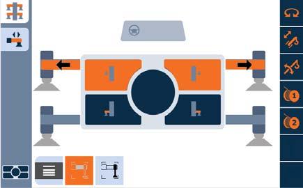
The rigging options on this screen enable the operator to select static rubber, pick and carry or outrigger configuration. The Outrigger Operation Menu is navigated on the lower CCS Screen.
To choose one of the outriggers’ proper positions, fully retracted, mid-extend or fully extended.

Outrigger Operation Menu
For choosing options during rigging. This is the only function where the menu button (3) (Figure3-13) will not automatically navigate directly to the menu screen. It must be selected and chosen with the menu icon on the lower left of this screen
Set the outriggers
The operator can choose which beam, or combination of beams, to extend or retract. Press the top of the Outrigger Function Enable Switch on the left armrest to select outrigger extension.


Raising the Jacks
Spin the jog dial clockwise and press OK button to select and choose jack operation. Press the lower side of the Outrigger Function Enable Switch on the left armrest to enable jack operation.
The operator can now choose which jack, or combination of jacks, to raise or lower.