8 minute read
OPERATING CONTROLS AND PROCEDURESRT540E OPERATOR MANUAL


Exhaust System Cleaning Switch
Warning
Extreme Heat Hazard!
During the cleaning process the exhaust becomes very hot. Do not park the vehicle near objects that are flammable.
Use caution near the exhaust tailpipe as it will also become very hot.
The Exhaust System Cleaning Switch (8) (Figure3-4) is located on the right side of the overhead control panel. This switch is a three position switch, Inhibit Cleaning/Permit Active Cleaning/Initiate Manual Cleaning. Center position enables clean to occur when required, or press this switch to force manual cleaning to begin immediately or to disable cleaning indefinitely:
• Manual Cleaning (7649-10)
• Inhibit Cleaning (7649-11)
To manually clean, set the crane parking brake, the crane transmission must be in neutral and have the brake and throttle pedals released. Refer to Exhaust System Cleaning (Tier 4 Only) , page7 for cleaning mode definitions and a description of when manual cleaning is needed.
Set up a safe area around the crane’s exhaust; remove tools, rags, grease or any debris from the engine exhaust area.
With the engine idling push the Cleaning Switch (8) to initiate manual cleaning.
Within 5 seconds the engine should rev up to 1000 to 1400 rpm. The engine will continue to run at this speed for up to 45 minutes.
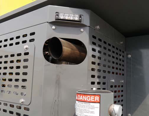
As a warning, the light (1, Figure3-5) above the exhaust pipe (2, Figure3-5) will blink during exhaust system cleaning.
Pressing brake or throttle pedal during cleaning or activating the Inhibit Cleaning Switch will interrupt the manual cleaning process.
Make sure the crane and surrounding area are monitored during manual cleaning. If any unsafe condition occurs, shut off the engine immediately.
During this period the sound of the engine may change. When manual cleaning is complete the engine will return to it’s normal idle speed.
Inhibit Regeneration
The Inhibit Regeneration Indicator (25) is located in the CCS display (Figure3-14). When the Regen Switch (7) (Figure3-4) is in the inhibit regeneration position, this amber indicator is illuminated and active and manual regeneration is prevented.
Diesel Exhaust Fluid
The Diesel Exhaust Fluid (DEF) Indicator (6) (Figure3-14) is located in the CCS display. The indicator has four different stages which will be triggered by the fluid level sensor in the DEF tank:
Low Tank - First warning to the operator is that the reducing agent in the tank is low. The DEF Indicator (6) will be lit continuously.
Derate - The DEF Indicator (6) will start to flash as a warning to the operator that a derate will be activated if the reducing agent in the DEF tank is not refilled.
Low Level Inducement - The DEF Indicator (6) will flash and the Engine Warning Indicator ( 17) will be lit continuously. Derate will be activated at this stage.
Severe Inducement - Once the DEF (6) tank is empty, the crane operation will be restricted. The DEF Indicator (6) will flash and the Stop Engine Indicator (16) is solid red.
Caution
Engine Damage Hazard!
Ultra low sulfur diesel fuel is required in Tier 4 engines. If “Ultra Low Sulfur” fuel is not used in engines that require it, the Cummins warranty will be void and the engine performance will quickly deteriorate and may stop running.
High Exhaust System Temperature
The High Exhaust System Temperature (HEST) Indicator (26) (Figure3-14) is located on the CCS Main Screen display.
During regeneration it is possible for the engine exhaust to reach temperatures exceeding 650° C (1200° F). The HEST indicator will illuminate red to warn the operator of when temperatures reach 675° C (1247° F) and will stay on until the temperatures falls below 625° C (1157° F).
A warning light near the tailpipe will flash during regeneration when high exhaust temperatures exist.
For more information on the regeneration process, refer to Diesel Particulate Filter (Tier 4 Engines Only), page 3-6.
Boom Lift/Main Hoist Control Lever (Dual Axis)
The Boom Lift/Main Hoist Control Lever (1) (Figure3-6) is located on the right armrest. The controller, when pushed to the right lowers the boom, or pushed left raises the boom.

When used for main hoist, the controller, when pushed forward lowers the cable, or pulled back raises the cable.
Swing/Telescope or Swing/Auxiliary Hoist Control Lever (Dual Axis)
Danger
Crushing Hazard!
Death or serious injury could result from being crushed by moving machinery.
Before actuating swing or any other function, sound horn and verify that all personnel are clear of rotating and moving parts.
The Swing/Telescope or Swing/Auxiliary Hoist (Swing/Tele or Swing/Aux) Control Lever (2) (Figure3-6) is located on the end of the left armrest. The lever controls the swing and, when the crane is not equipped with an auxiliary hoist, telescope functions. When equipped with an auxiliary hoist, the lever controls swing and auxiliary hoist functions and telescope functions are controlled through a foot pedal.
Positioning the lever to the left or right actuates a control valve to provide 360 degree continuous rotation in the desired direction. Positioning the lever forward actuates the control valve to telescope the boom out and pulling the lever back actuates the boom to telescope in.
If equipped with an auxiliary hoist, positioning the lever forward actuates the control valve to let out hoist cable and pulling the lever back reels the cable in. Moving the lever in a diagonal direction actuates the two functions simultaneously.
Main Hoist Enable Switch
The Main Hoist Enable Switch (3) (Figure3-6) is a momentary switch that is located on the right armrest. Press once to enable hoist; press again to disable hoist. Pressing the switch twice rapidly enables hoist at high speed. Pressing once and holding the switch for about 2 seconds also enables high speed.
Boom Up Bypass Switch (Optional)
The Boom Up Bypass Switch (4) (Figure3-6) is a momentary two-position rocker switch that, when installed, is located on the right armrest. While lift function is enabled and in a RCL lockout condition, activating the Boom Up Bypass Switch will enable boom lift up.
Lift Function Enable Switch
The Lift Function Enable switch (5) (Figure3-6) is a momentary switch that enables boom up and boom down.
Jog Dial
The Jog Dial Control (6) (Figure3-6) is located on the right arm rest. It selects and chooses functions on the screen(s) to navigate the Crane Control System.
Outrigger Function Enable Switch
The Outrigger Function Enable Switch (7) (Figure3-6) allows the operator to switch between extension/retraction of the outriggers and raising/lowering of the jacks. Press and hold this switch to force the lower screen display to change to the outrigger page.
Differential Lock On/Off Switch (Optional)
The Differential Lock Switch (8) (Figure3-6) is located on the left arm rest. It engages the differential lock function for better traction, when Four Wheel Drive is selected, on poor road or highway surfaces. It can be activated for a maximum of 30 seconds at a time.
NOTE: The differential lock will only work when the crane is in the 4WD mode.
Rear Steer Switch
The Rear Steer Control Switch (9) (Figure3-6) is a threeposition, spring centered to off, rocker switch, located on the left armrest. Press the bottom of the switch to actuate a control valve to turn the rear wheels to the left, causing the crane to turn to the right. Press the top of the switch to actuate a control valve to turn the rear wheels to the right, causing the crane to turn to the left. When the wheels are not centered the Wheels Not Centered icon on the CCS Operating Display illuminates. Releasing the switch causes it to return to the center off position.
To straighten the rear wheels press the switch until the Rear Wheels Not Centered icon indicator light goes off.
Auxiliary Hoist Enable Switch (Optional)
The Auxiliary Hoist Enable Switch (10) (Figure3-6) is located on the left arm rest. It enables the Auxiliary Hoist and sets the high speed the same as the Main Hoist Enable Switch does for the Main Hoist.
Boom Telescope Enable Switch
The Boom Telescope Enable Switch (11) (Figure3-6) is located on the left arm rest. It enables the boom telescoping function for the optional Telescope Control Foot Pedal, or for the Control Lever (joystick) if there is no auxiliary hoist.
Swing Enable Switch
The Swing Enable Switch (12) (Figure3-6) is located on the left arm rest. This two-position rocker switch (On/Off) is used to control a hydraulic valve that directs a regulated flow of pressure to and from the swing brake. When the joystick moves to swing the crane the brake releases. When the crane stops swinging the swing brake re-engages.
Seat Slide Lever
Moving the Seat Slide Lever (13) (Figure3-6) will enable only the seat to slide, either forward or backward.
Air Conditioner/Heater Climate Unit
The crane cab Air Conditioner/Heater Climate Unit (14) (Figure3-6) is located in the cab under the driver’s seat. The vents (15) are part of the climate unit and can be adjusted to direct the flow of air.
Seat Slide Lever
Moving the Seat Frame Slide Lever (16) (Figure3-6) will slide both the seat and the arm rests either forward or backward.
Armrest Adjustment Knobs
The left and right armrest and armrest controls can be adjusted using the adjustment buttons (17) (Figure3-6) found under the rear of the armrest. Press the button to rotate the entire armrest; release button at the desired position.
Seat Height Adjustment Lever
To adjust the height of the seat, lift the height adjustment lever (18) (Figure3-6) and then adjust the seat as needed.
Rated Capacity Limiter (RCL) Bypass Switch
The RCL Bypass (Override) S witch (19) (Figure3-6) is a momentary type switch. Turn the key clockwise to bypass the 3rd Wrap Indicator and Anti Two-Block Switch. It will be bypassed only as long as the switch is held in this position. Turn the key counterclockwise to bypass the Anti Two-Block Switch, Rated Capacity Limiter (RCL) and 3rd Wrap Indicator (hoist lowering limit). It is important to read and understand the RCL Override Warning information before using the RCL Bypass or On/Off Switch.
Emergency Stop Switch
The crane Emergency Stop Switch (20) (Figure3-6) is located on the cab right console and is used to shut down the crane’s engine. Push the red button in to shut down the engine, which illuminates the Emergency Stop icon on the CCS operator display. Rotate the knob and pull out to resume normal operation.
Level Indicator
The Level Indicator (21) (Figure3-6) is located on the right side of the cab by the Emergency Stop Switch. The indicator provides the operator with a visual aid in determining the levelness of the crane.
Deadman Switches (Optional) (Dual Axis Joysticks only)
The Deadman Switches (22) (Figure3-6) are located on the front of both control levers. Either of these switches can be used instead of the seat switch to keep crane functions active.
Hoist High Speed Toggle Switches
The Hoist High Speed Toggle Switches (23) (Figure3-6) are thumb operated two-position center spring return switches. Pressing the right side maintains high speed until it is deactivated; pressing the left is momentary speed increase.
Horn Button
The Horn Button (24) (Figure3-6) is located on the upper front of the right control lever. The button sounds the horn during craning operations.
Free Swing Button
The Free Swing Button (25) (Figure3-6) is located on the upper front of the left control lever. The Free Swing Button releases the Swing Brake and allows the boom to be centered over the load.
Cab Door Release Lever
Use the Cab Door Release Lever (26) (Figure3-6) to open and close the cab door from inside the cab.
Hoist Rotation Indicators (Not Shown)
The Hoist Rotation Indicators (27) (Figure3-6 Item Numbers) for the auxiliary and main hoists are located on top of each hoist control lever (1, 2) (Figure3-6). Each indicator is electronically driven by an input signal from a sensor attached to its related hoist and an output signal from a control module. Each hoist control lever (1, 2) pulses when its hoist is running so the operator’s thumb can sense it.
Seat Switch (Not Shown)
This switch (28) (Figure3-6 Item Numbers) is located within the seat. An operator must be sitting in the seat, enabling the switch, before any crane functions can be activated.