7 minute read
MAINTENANCE INTERVALS

For
Central body standard bevel gears - UTTO (API GL4), or gear: J20/C, MF M1143, or gear: SAE80W/90 (API GL4 or GL5)
Central body hypoid bevel gears - SAE80W/90 (API GL5)
UTTO (API GL4) J20/C; or gear: SAE80W/90 (API GL4 or GL5)
If with limited slip differential, and/or wet brakes, use LS additivated oils. Clean carefully oil plug magnet.
Clean carefully oil plug magnet.
Clean carefully oil plug magnet. *in accordance with Machine Service requirements Only gears - UTTO J20/C, or gear: SAE80W/90 (API GL4 or GL5)
Gears with wet discs clutch - ATF GM Dexron IIE, Dexron III
Not applicable Service lock, etc.) use ATF oil e.g. GM Dexron IIE, Dexron III
DOTbrakefluidsoilsareNOTcompatible w/stdoils
Check for any damage or corrosion of treads or mating surfaces
EP or NLGI3 EP Supply grease until clean grease is visible from outside. Grease performance level acc. to: Ac- cording to DIN 51825 level KP2K-30 (NLGI2) or KP3K-20 (NLGI3); ASTM D4950 NLGI2 GC-LB
In case of severe duty, half oil change intervals must be applied. In case of extreme enviroments, chatter noise, reduce oil change intervals accordingly. In case of extremely low ambient temperatures (<-20°C), use appropriate oils w/ low viscosity: UTTO J20/D (std Bevel Gears), SAE 75W/90 API GL5 LS (Hypoid Bevel Gears: models 192, 193, 194).
API GL5: Acc. To MIL L-2105-B
See PSB 00279 (latest update) for more info regarding lubricants and viscosity grades.
30.1.8 LUBRICANT & SEALANT SPECIFICATIONS
1. Locking, sealing and lubricating materials referred to in this manual are the same used in the shop-floor.
2. The table below gives an account of the typical applications of each single material, in order to facilitate replacement with similar products marketed by different brand names with different trademarks.
LOCTITE 242
Anaerobic product apt to prevent the loosening of screws, nuts and plugs. Used for medium-strength locking. Before using it, completely remove any lubricant by using the specific activator.
LOCTITE 243
The oleocompatible alternative to 242. Does not require the activation of lubricated surfaces.
LOCTITE 270
Anaerobic product for very-high strength locking of screws and nuts. Before using it, completely remove any lubricant by using the specific activator.
To remove parts, it may be necessary to heat them at 80° C approximately.
LOCTITE 275
Anaerobic product suitable for high-strength locking and sealing of large threaded parts, bolts and stud bolts, for pipe sealing and for protecting parts against tampering; suitable for sealing coupling surfaces with a maximum diametrical clearance of 0.25 mm.
LOCTITE 510
Anaerobic product for the hermetic sealing of flanged units and screw holes communicating with fluids. Can seal clearances between flanges up to 0.2 mm.
LOCTITE 577
Quick anaerobic sealant for sealing threaded portions of conical or cylindrical unions up to M80. Before using it, remove any lubricant with the specific activator. After polymerisation, disassembly may result rather difficult, so heating may be necessary for larger diameters.
LOCTITE 638
Anaerobic adhesive for fast and high-strength gluing of cylindrical metal joints (hub on shaft). Can glue together parts with clearance ranging between 0.1 and 0.25 mm.
LOCTITE 648
Anaerobic adhesive for fast and medium-strength gluing of cylindrical metal joints (hub on shaft). Can glue together parts with radial clearance below 0.1 mm.
AREXONS (REPOSITIONABLE JOINTING COMPOUND FOR SEALS)
Solvent-based sealing compound for elastic seals, drying through evaporation. Used for sealing the outer diameter of sealing rings for rotating shafts with outer metal reinforcement.
SILICONE
Semi-fluid adhesive material used for sealing and filling and to protect components from environmental and physical elements. Polymerises with non-corrosive dampness.
TECNO LUBE/101 (SILICONE-BASED GREASE)
Highly adhesive synthetic grease, with silicone compounds added. Applied to adjustment screws with hole communicating with oil-type fluids. Used when frequent adjusting is required.
MOLIKOTE (DOW CORNING)
Lubricating compound containing molybdenum disulphide, used to lubricate articulation pins and to prevent sticking and oxidation of parts that are not lubricated on a regular basis.
(LITHIUM-BASED) GREASE
Applied to bearings, sliding parts and used to lubricate seals or parts during assembly.
Safety Precautions
1. During all operations described in this manual, the axle should be fastened onto a trestle, while the other parts mentioned should rest on supporting benches.
2. When removing one of the arms, an anti-tilting safety trestle should be placed under the other arm.
3. When working on an arm that is fitted on the machine, make sure that the supporting trestles are correctly positioned and that the machine is locked lengthways.
4. Do not admit any other person inside the work area; mark off the area, hang warning signs and remove the ignition key from the machine.
5. Use only clean, quality tools; discard all worn, damaged, lowq uality or improvised wrenches and tools. Ensure that all torque wrenches have been checked and calibrated.
6. During maintenance operations, always wear protective glasses, safety footwear, protective gloves and all P.P.E. (Personal Protective Equipment) in function of the risks which the workers may be exposed to.
7. Should you stain a surface with oil, remove marks straight away.
8. Dispose of all lubricants, seals, rags and solvents once work has been completed. Treat them as special waste anddispose of them according to the relative law provisions obtaining in the country where thea xles are being overhauled.
9. Make sure that only weak solvents are used for cleaning purposes; avoid using turpentine, dilutants and toluol, xylolbasedorsimilar solvents; use light solvents such as Kerosene, mineral spirits or water-based, environment friendly solvents.
10. For the sake of clarity, the parts that do not normally need to be removed have not been reproduced in some of the diagrams.
11. For agricultural axles, the terms RIGHT and LEFT refer to the position from operator’s seat. For construcition axle,the terms RIGHT and LEFT refer to the position outside facing the machine (with the input drive facing forward).
12. After repair work has been completed, accurately touch up any coated part that may have been damaged.
13. Follow all safety instructions in the Original Equipment Manufacturer (OEM) manual that came with the vehicle.
14. Before draining oil, release the internal pressure, for details see OIL DRAINING MANDATORY PROCEDURE.
Disassembly
CAUTION !
Before draining oil, release the internal air, for details see OIL DRAINING MANDATORY PROCEDURE.
CAUTION !
Perform all operations on both arms.
If
NOTE !
“A”.
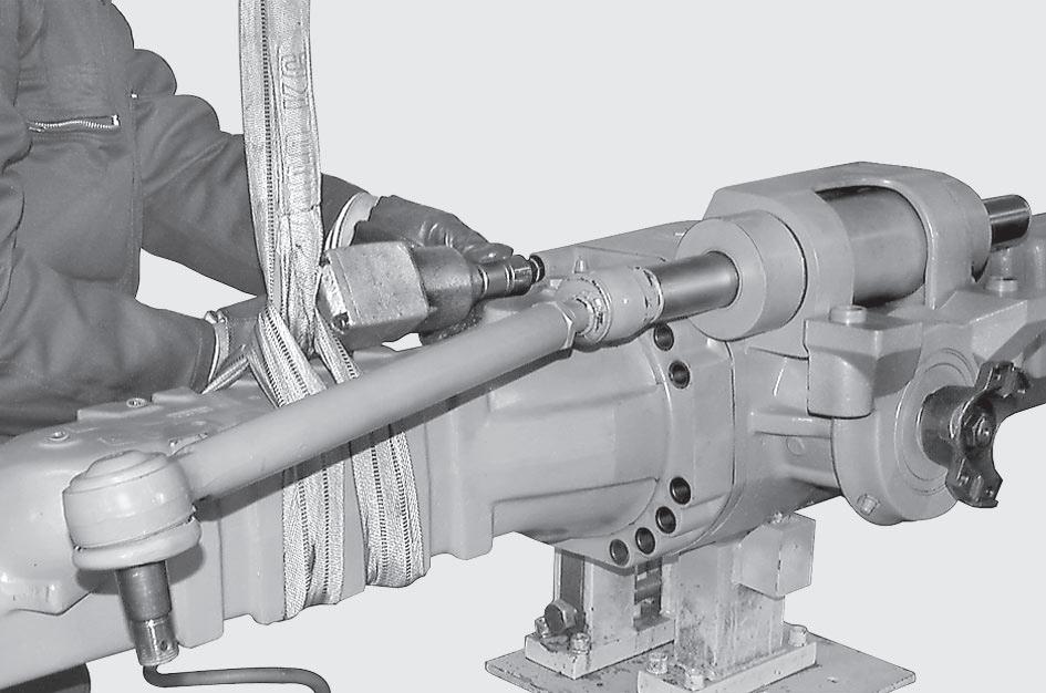
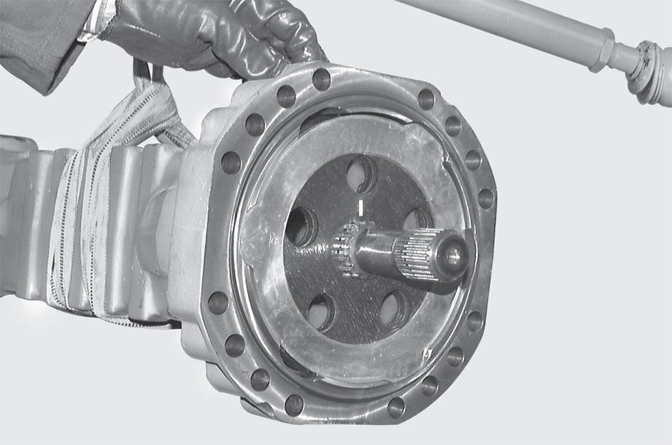
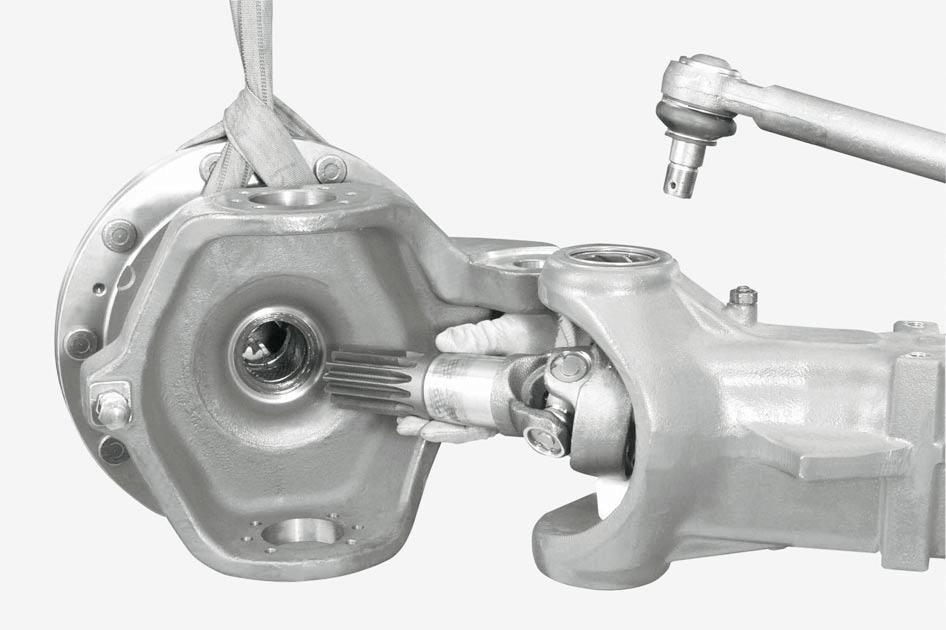
Disconnect the pins of the steering bars from the steering case (See STEERING CYLINDER). Sling the arm (3) to be removed and put the rod under slight tension.
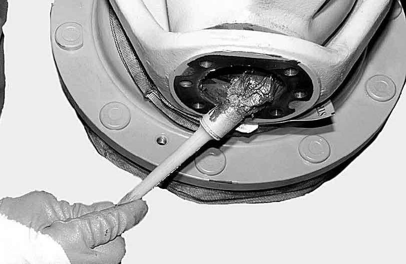
Remove the oil-level plug (1).

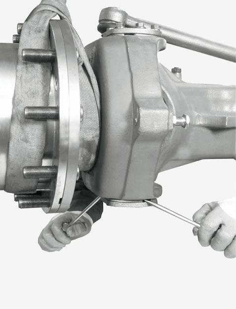
Loosen and remove the screws (4) that fix the arm (3) to the central body (6).
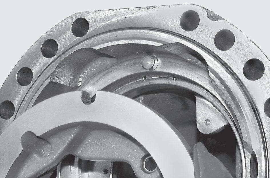
Apply the brakes and, keeping them under pressure, check the linings “S” between the disks using tool T1 (See drawing T1).

Minimum “S”: 4.5 mm.
CAUTION !
Replace the braking disks and the intermediate disks on both sides if necessary.
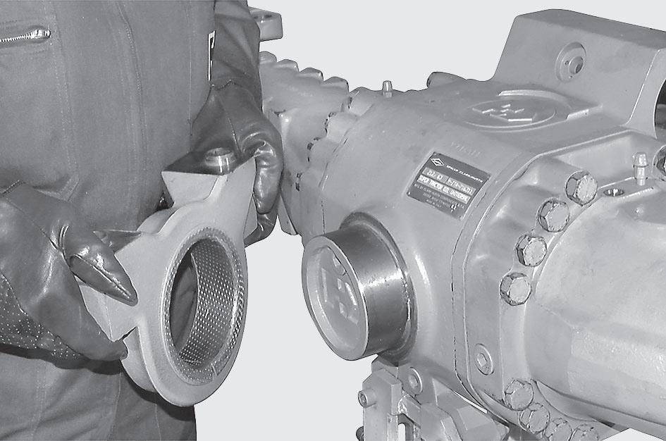

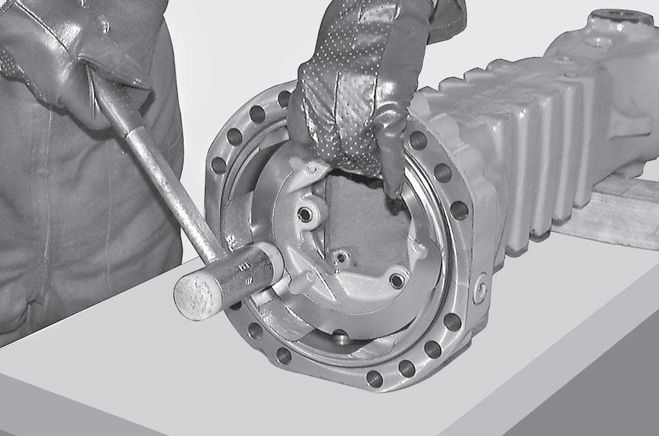
Remove the swing support (2) on the side opposite th drive.
Remove the arm (3) together with the pack of the braking disks (7). Place the arm on a bench
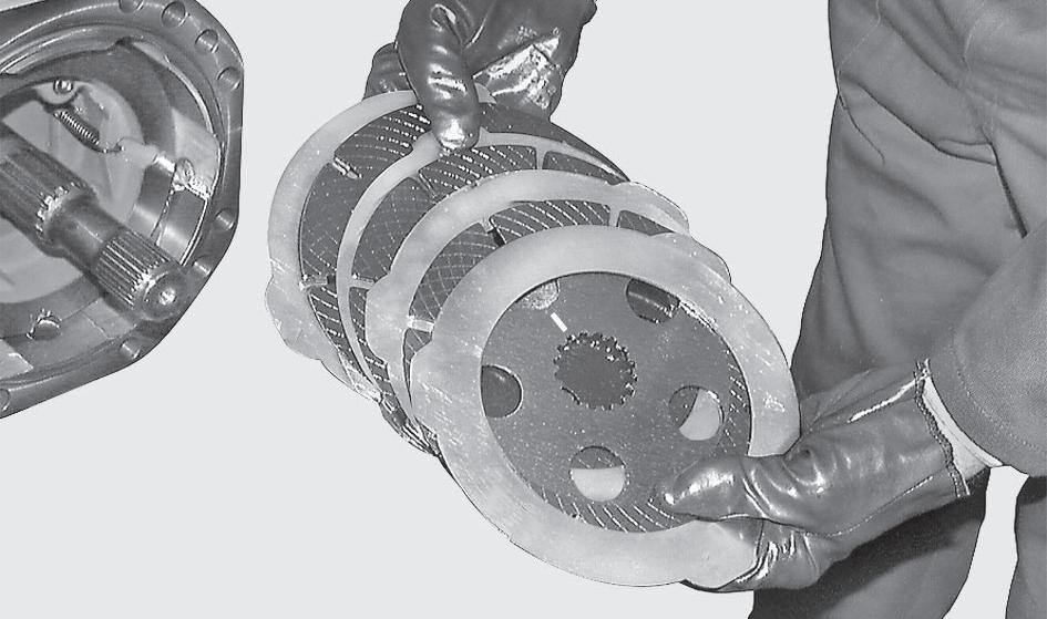
Remove the braking disks (7) and write down their order of assembly.
NOTE !
1. If the disks do not need replacing, avoid switching their position.
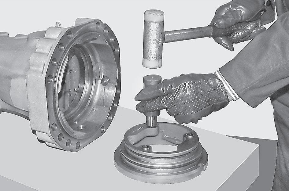
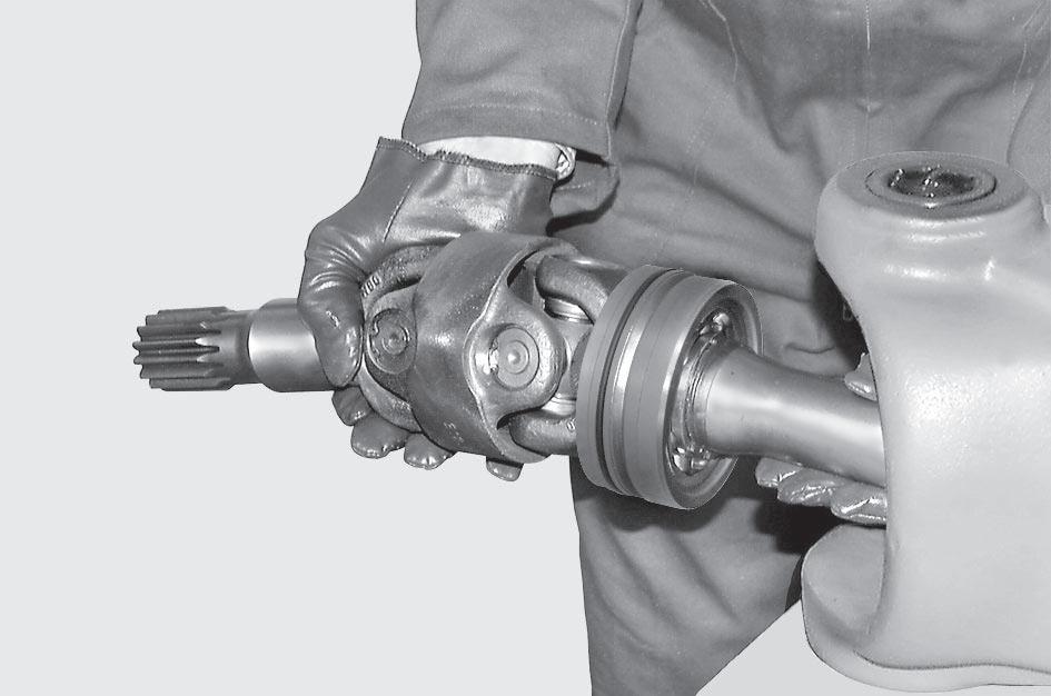
2. Extract the u-joint (18).
Remove the reversal springs (8) from the piston (9).
NOTE !
If the springs (8) are weak or deformed they must be replaced.
Slowly introduce compressed air through the connection of the braking circuit in order to extract the entire piston.


CAUTION !
Hold on to the piston as it may be suddenly ejected and damaged.
Remove the pin screws (10) guiding the piston (9).
CAUTION !
If the screws are to be replaced, write down the different colors for the different brake gap.
Accurately clean the piston (9) and the seats of slide and seal. Replace the o-rings (11) and (12) and the anti-extrusion rings (13)and (14); make sure that the assembly side is correct.

CAUTION !
Make sure that the piston seat fits into the stop pin (A) inside the
Fit the pin screws (10) making sure that they are all of the same color.
See Service Part List “Brake” section for bolt color detail. Apply Loctite 270 to the thread. Torque wrench setting: 5 - 7 N·m.
Fit the reversal springs (8) on the piston (9).
CAUTION !
Pay attention not to deform the connections of the springs.
Slightly lubricate the braking disks (7) and fit them in the arm following the correct sequence; orient them so that the oil circulation holes and the marks “B” are perfectly lined up.
NOTE !
When installing the steel discs, the slot corresponding to the oil level cap should always be kept free. 16
Check that the positioning of the sealing ring (16) on the arm is intact; install the complete arm. Lock it into position using two screws (4) and washers (5).


T2
Check the flatness of the arms using tool T2 (See drawing T2 ) and finally lock the arms with the screws (4) and the washer (5) using the criss-cross method. Torque wrench setting: 298 N·m
30.4 COMPLETE STEERING CASE
SASSEMBLY CAUTION !
Before draining oil, release the internal air, for details see OIL DRAINING MANDATORY PROCEDURE.


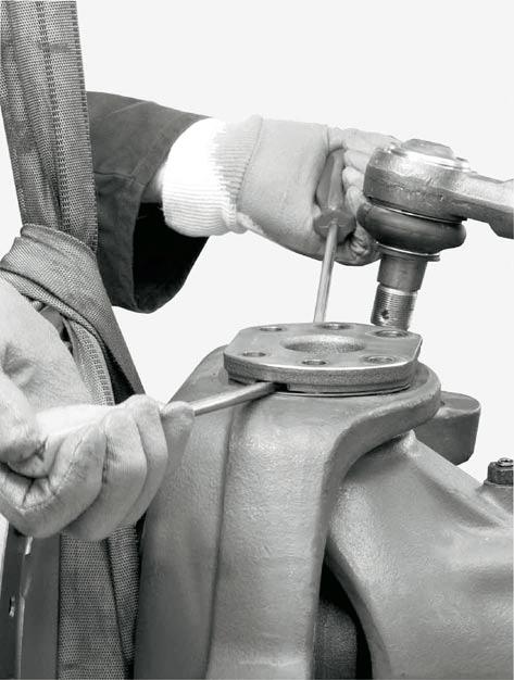


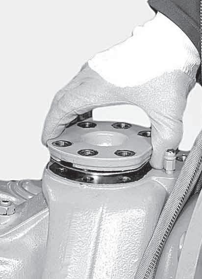
Using two levers, remove the top articulation pin (4) complete with front seal (9) and shims (3).
CAUTION !
Pay attention not to damage the surfaces.
Using two levers, remove the top articulation pin (4) complete with front seal (9) and shims (3).
CAUTION !
Pay
Fit a new seal (3) onto the top articulation pin (4). Lubricate and install the unit in the steering case. Position the screws (8) and tighten with torque wrench 140N·m.


Check the correct assembly side of the

(3).
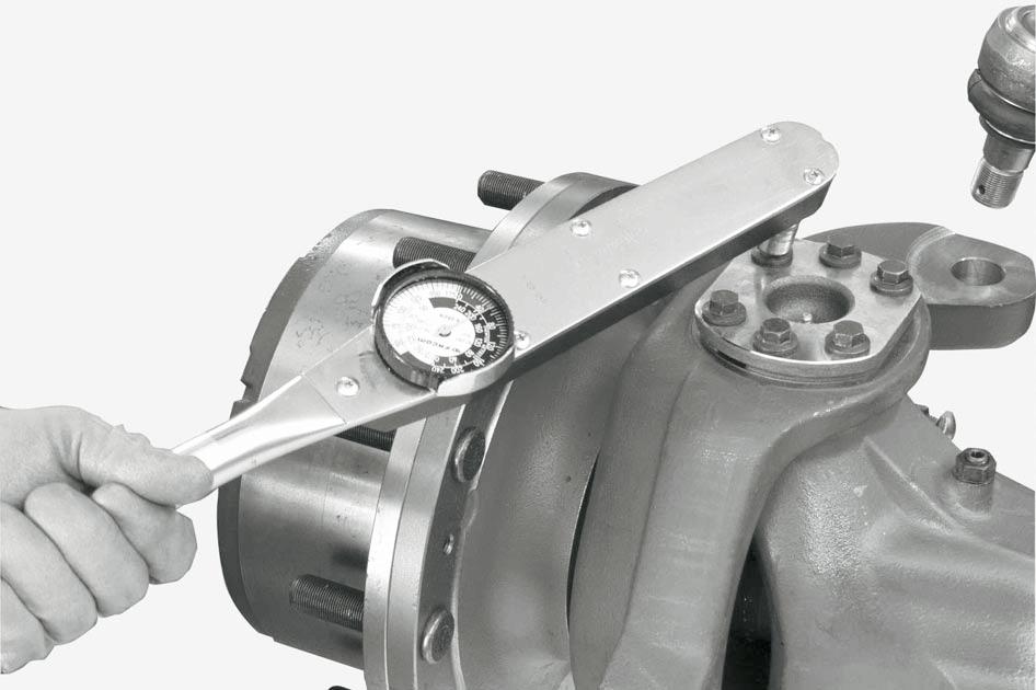
Tighten the new capscrews (15) of top and bottom articulation pins in sequence using the
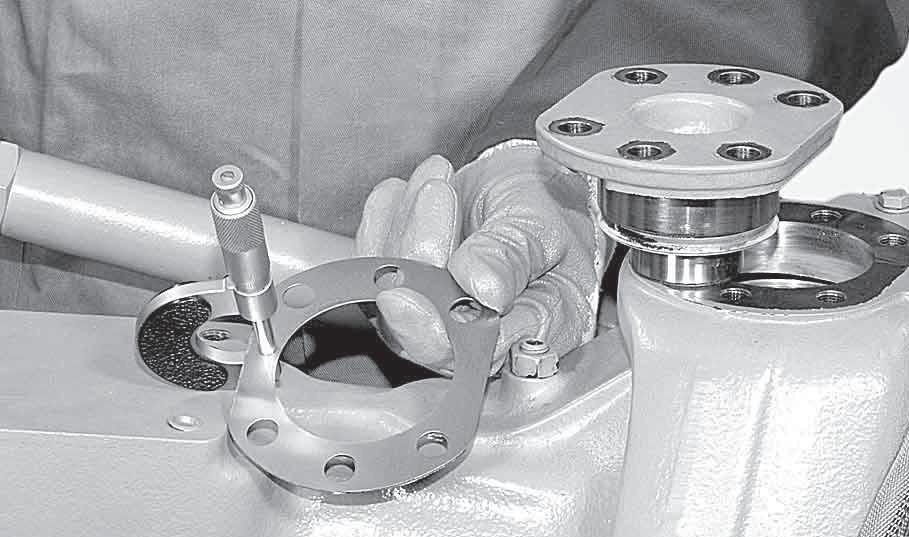
Check with a lever that there is no vertical gap. In case there is any gap, determine the width and reduce it by removing shims.

30 - 60 N·m
Check the torque of the pins, which has to be between 30 and 60 N·m.
If the preliminary measured value is too high, the shims have to be increased.
Before draining oil, release the internal air, for details see OIL DRAINING MANDATORY PROCEDURE.


NOTE !
If necessary, for
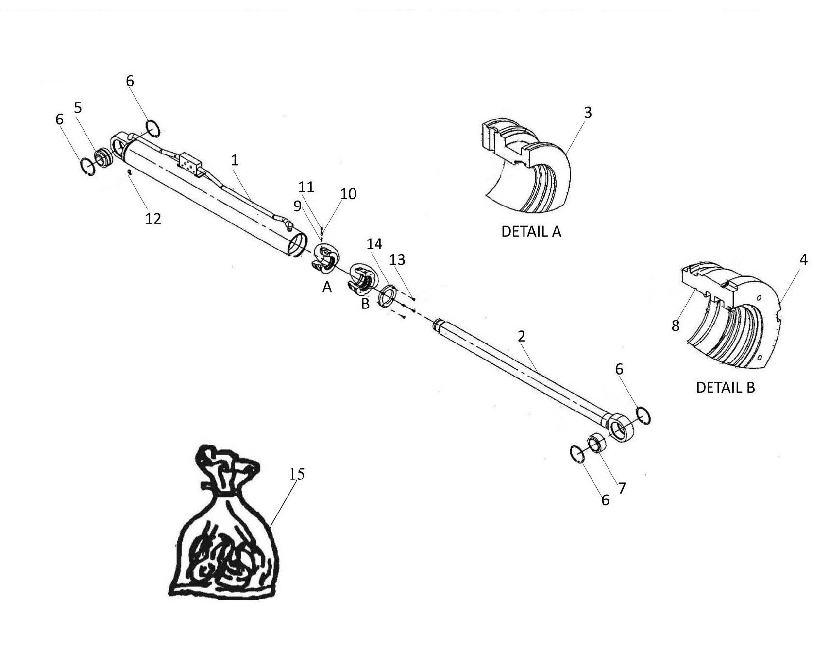
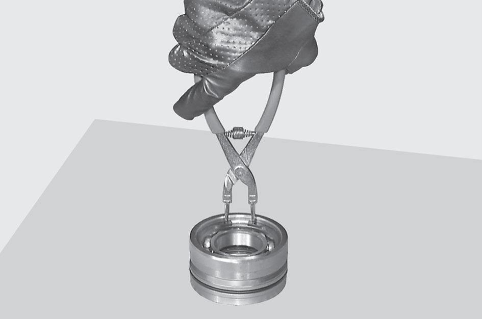
Remove the snap ring (9) from the bushing unit (13).
Remove the snap ring (10) from the bearing (11). Use a puller to remove the bearing (11), the sealing ring (12) center the point of the check


NOTE !
Write the assembly side of the ring (12).
NOTE !
Torque wrench setting: maximum 15 N·m.


NOTE !
For u-joint coming with a in the slot.