5 minute read
OPERATING PRINCIPLE


Low pressure steam circuit
Engine
Hot air discharge
Alternator
E
Elec tromagnetic clutch Compressor
Warm air
Filters
Centrifugal fan ( Turbine)
Evaporator
High pressure steam circuit
A xial fan
Condenser
Drier Filter switch
Binar y pressure
Indicator lamp
High pressure liquid circuit
Pressure reducing valve
Low pressure liquid circuit
Thermostat
Condensation water drainage
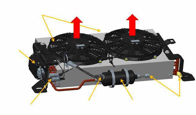
Description Of Components
The Compressor
The compressor circulates the fluid through the circuit, drawing it in as a low pressure and low temperature gas from the evaporator and sending it to the condenser as a high pressure, high temperature gas.
The Condenser
The condenser is a thermal exchanger that transmits the heat recuperated from the evaporator to the outside air by means of the fan and causes the condensation of the fluid at highpressure.
The Drier Filter
The filter is the main protective component in the system. It performs the following functions:
Filtering any solid particles carried by the fluid that could damage the compressor or obstruct the reducing valve, for example Dehumidifying the fluid and the oil to protect all the components to protect all parts of the circuit from corrosive substances and freezing moisture at the outlet of the pressure reducing valve. Storing the fluid in liquid state and thus constituting a buffer tank to compensate for pressure variations. It therefore helps to absorb pressure differences generated by the compressor.
THE “ BINARY ” PRESSURE SWITCH
Mounted on the drier filter, the pressure switch is the system’s safety device which is sensitive to pressure variations. It protects the system against both excessively low pressures and excessively high pressures by directly controlling the compressor clutch. Acts against low pressures (below 2 Bar) due to a lack of refrigerant, a leak or a downstream circuit blockage. Acts against high pressures (greater than 27 Bar) due to incorrect compressor cooling, an excess of refrigerant or an upstream circuit blockage.
The Reducing Valve
The pressure reducing valve is mounted on the evaporator inlet. By expansion, it lowers the pressure and thus the temperature of the fluid in such a way as to cool the air passing through the evaporator. It adjusts the flow to calibrate the quantity of fluid in such a way that it is completely vaporised at the evaporator outlet.
The Evaporator
The evaporator is a heat exchanger fitted with a pressure reducing valve and a fan. The fan draws air across the cold evaporator fins. As the air passes across the fins the moisture it contains condenses and the air leaves the evaporator cooled. This heat exchange allows the coolant to evaporate at low pressure.
ANTI - FROST THERMOSTAT
The electric thermostat is connected to a sensor located between two evaporator fins. Temperature variations in the evaporator lead to changes in the resistance of the potentiometer in the preset thermostat and this controls the compressor clutch relay.
110.3.1 GENERAL CHECK POINTS
WARNING
Only operators who are certified to handle refrigerant fluids may work on the air conditioning system, otherwise please contact a specialist air-conditioning company.
Before repairing or diagnosing the A/C system, first check the following points:
- Check the positions of all control buttons referred to in the operator’s manual.
- Visual inspection of A/C
- Checking the condenser cooling fins to ensure that there are no obstructions, such as insects, leaves or grass.
- The condenser fans are operating and turning in the correct direction.
- Check the condition and the tension of the compressor’s drive belt and repair if necessary.
- Compressor operates in on/off cycles.
- Evaporator hoses are not obstructed.
- Fan runs at all operating speeds.
- Water valve fully closed.
- Air vent opens and closes fully.
110.3.2 AIR-CONDITIONING ELECTRICAL SYSTEM CHECK POINTS
- Fan is switched on and working.
- Voltage from condenser to connectors.
- Voltage from relay block to at least 1 fan (fans switched from series to parallel when medium pressure (switch is closed).
- The two condenser fans are working.
- Compressor clutch voltage via condenser connector.
- Signal voltage to compressor.
- Compressor clutch engagement.
- Compressor housing is constant or there is an electrical ground connection to the compressor.
110.3.3 ASSEMBLY INSTRUCTIONS FOR AIR - CONDITIONING CIRCUIT
WARNING
Only operators who are certified to handle refrigerant fluids may work on the air conditioning system, otherwise please contact a specialist air-conditioning company.
Carry out the assembly operations in a dry and dust free area. Use PAG ISO SP20 oil for lubricating all seals and seal surfaces before assembly.
110.3.4 SAFETY MEASURES FOR HANDLING R134A
1. Individual protection: protective goggles and rubber gloves.
2. Perform the operations in a ventilated space.
3. First aid: After inhalation, breathe clean air, give oxygen or perform mouth-to-mouth resuscitation according to the degree of urgency (medication contraindication). Consult a doctor. In the event of contact with the eyes, rinse thoroughly for 15 minutes and see a doctor. In the event of contact with the skin, rinse thoroughly and remove contaminated clothing.
4. Storage conditions: keep R134a in a sealed container in a dry, cool and well ventilated place.
5. Handling: only in ventilated areas.
6. Measures to be taken in case of accident: wear a self-contained breathing apparatus if R134a is exposed to fire.
110.3.5 REFRIGERANT FLUID LOAD FOR THE AIR CONDITIONING CIRCUIT
- Refrigerant fluid : R134a
- Charging equipment : Charging station
- Quantity of fluid : 1500 g ± 50 g and 245 ml of PAG ISO SP20 oil.
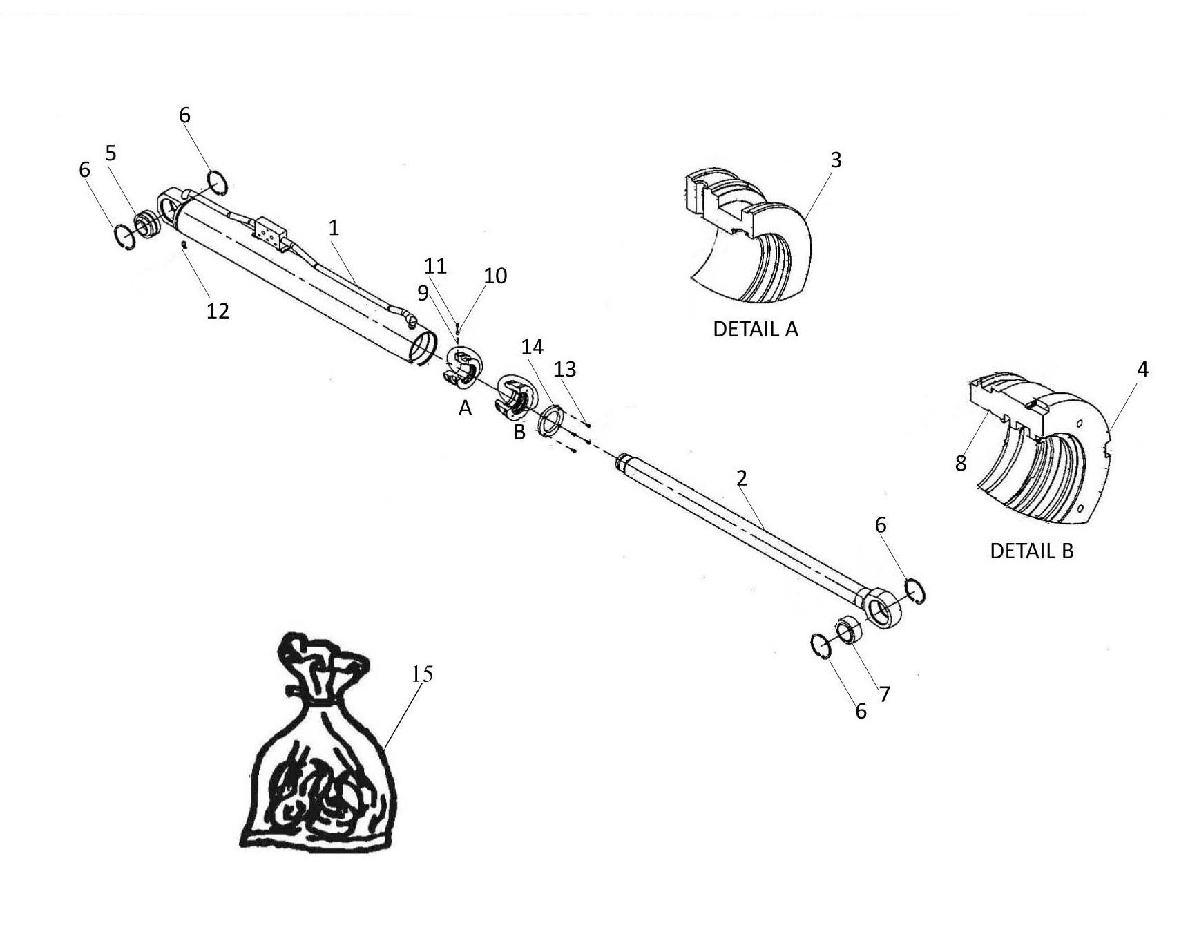
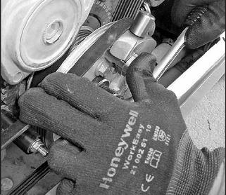
110.4 AIR - CONDITIONING BELT -REMOVAL
Fix the special wedge (1) on ribbed pulley (2). Lock the wedge with the nut (3). Make the rotation movement on the pulley shaft (4). This will drive the tool and lift the belt.
Pull the belt(5) by hand to release it, continue turning and remove the belt and the tool.
110.5.1 PRESSURE TROUBLE SHOOTING
Problem. Low pressure manometer Low pressure manometer
Normal Normal
Little or no cooling
Normal or low Low
Normal or high High
High Normal or low
Probable cause
Hot air infiltration into the appliance or evaporator block. Hot water infiltration at the heating water valve position or faulty water valve.
Normal situation if ambient temperature is very low. Obstruction in the HP hose connected between the compressor and the condenser-filter- evaporator. Before the HP reading point. Check for leaks. Very low quantity of coolant. Faulty compressor
Normal situation if the ambient temperature is very high. Excess coolant load. 5 - 35% of condenserobstructed Air present in the A/C system
Obstruction in the HP hose connected between the compressor and the condenser-filter-evaporator. After the HP reading point. Check for leaks. Compressor belt has jumped, probably due to poor pulley alignment. Compressor clutch not engaged, compressor damaged
Hose suction and discharge inverted on the compressor clutch. Clutch not engaging. Pressure reducing valve blocked in open position. Compressor damaged.
Normal or high Drier filter saturated with moisture
110.5.2 ABNORMAL NOISE ON A/C SYSTEM
Sometimes, for a variety of reasons, the A/C system may produce an abnormal noise. The following are possible examples
Causes
Problem
Solution
1 The belt is worn or slipping. Check belt wear and tension
2 Noise of belt on the pulley. Replace
3 Electric clutch plate slippage. Check that the clearance between the compressor pulley and the clutch is 0.3-0.5 mm
4 Compressor support plate vibration and resonance. Ensure that the bolts are properly tightened and the plate is correctly positioned.
5 Whistling expansion valve. If the noise persists, replace the valve.
110.5.3 UNPLEASANT SMELL
- Under certain conditions, mould and bacteria (normally present in the air) may form on the surface of the evaporator core, producing an unpleasant smell inside the cab.
- Treat the evaporator with an anti-bacterial product. Keep the evaporator clean.
- Switch off the A/C system a few minutes before switching off the machine, while leaving the fan running (this will dry the moisture from the evaporator core which encourages bacteria growth).
Intentionally Left Blank