5 minute read
50.4 BOOM CONTROL AND ADJUSTMENT

50.4.1 P REPARATION AND SAFETY INSTRUCTIONS.
- Stabilize the machine on a horizontal floor.
- Deactivate battery power supply using a battery cut - off.
- Decompress all hydraulic elements.
Whole boom weight = about 3092 Kg
Specific tools:
- Lifting system (Hoist +sling)
- Mallet
- Presser foot
- Wooden chock
- Cord
- Trestles
- Channel lever - 50 “Specific tooling”
- Hose path fittings - 50 “Specific tooling”
- Hosing tension setting shim - 50 “Specific tooling”
- Chain checking gauge - 50 “Specific tooling”
50.4.2 IMPORTANT INFORMATION
Check internal chain wear during dismantling procedure.
“Check wear on boom chains”.
When changing a chain, replace it with a pair and measure the difference in length between the chains.
In the case of a dismantling and reassembly operation without chain exchange (not replacing worn chains with new ones), take the pre-setting dimensions (Item 7 & 8) on the machine before dismantling. These dimensions will be used during reassembly for setting chain tensions.
”Chain tension pre-settings”.
Pre-setting example :
Captions :
50.4.3 CHECK WEAR ON BOOM CHAINS
External Chains
Chain wear occurs at a number of locations:
1. On the articulations, which leads to elongation of the chain.
2. On the edge of link plates through contact with the pulleys.
3. On the face of the plates and the extended pins through contact with the pulley flanges.
4. On the alignment of the flats of the extendedpins.

Chain Elongation
We recommend that you perform this operation using the chain checking gauge.
50 - “Specific boom tooling”
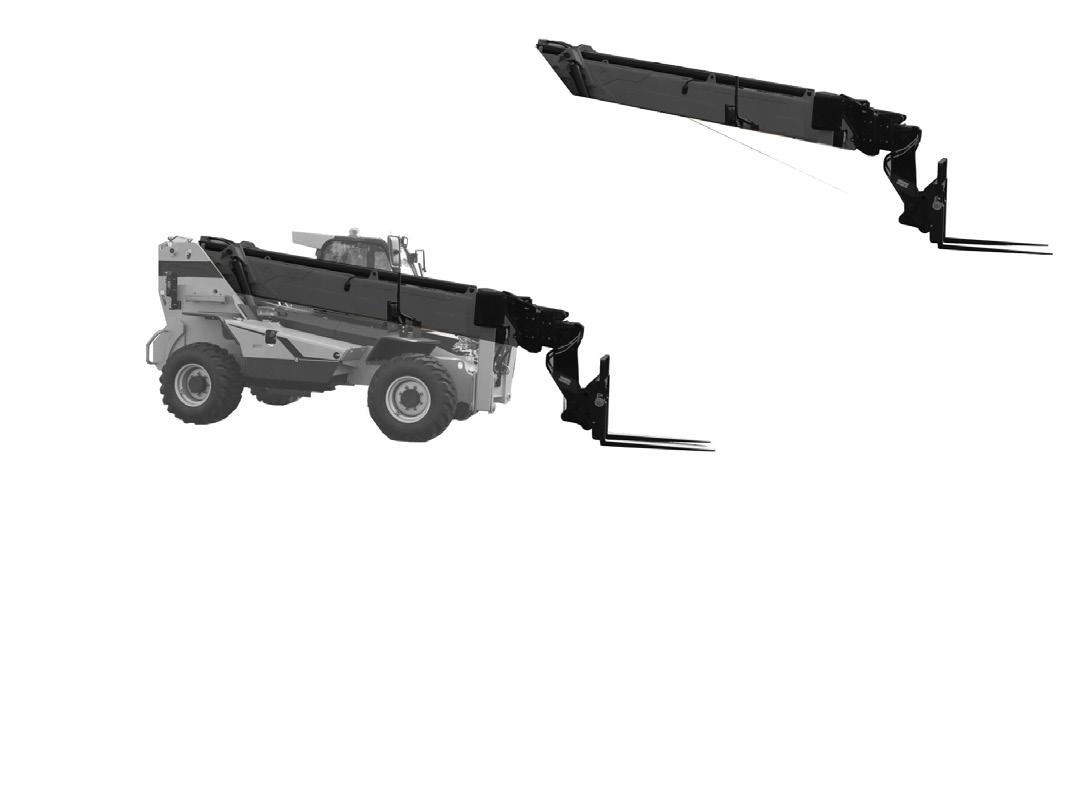
- Set the lift truck on its stabilisers, with the boom horizontal.
- Fully extend the telescopes and continue operating the control for a few moments to properly tension the chains.

- As the chain will likely wear unevenly over its length, divide the chain into 4 equal sections and check with the gauge at the centre of each section.
If the maximum dimension is exceeded ( 228,6 mm + 2 % = 233,2 mm ), replace the pair of chains.
Side Wear Of Plates
As for chain elongation, perform a check in the middle of each section using a calliper gauge.
If the dimension is less than the minimum dimension (24 mm -2% = 23,5 mm and 15,5 mm -2% = 15,2 mm), replace the pair of chains.
Extended Pin Wear
As for chain elongation, perform a check in the middle of each section using a calliper gauge.
If the dimension is less than the minimum dimension (53,6 mm -2% = 52,5 mm and 42,25 mm-2% = 41,4mm), replace the pair of chains.
In addition to wear, the high pressures between the side of the plates and the pulleys may force out material, causing the articulations to seize. Replace the pair of chains in this casealso.
Alignment Of Extended Pin Flats
Check the chains over their entire length. High friction between the plates and the extended pins may cause the pins to turn in the outer plates and thus come out of their housing.
If the flats are not aligned in the longitudinal direction of the chain, replace the pair of chains.
Inner Chains
The telescopes need to be dismantled to check the boom inner chains. “Dismantling chain boom components”.
Chain wear occurs at a number of locations:
- On the articulations, which leads to elongation of the chain.
- On the edge of link plates through contact with the pulleys.
- On the face of the plates and the extended pins through contact with the pulley flanges.
- On the alignment of the flats of the extended pins.
Chain Elongation
We recommend that you perform this operation using the chain checking gauge.
50 - “ Specific boom tooling ”
As the chain will likely wear unevenly over its length, divide the chaini nto 4 equal sections and check with the gauge at the centre of each section.
Side Wear Of Plates
As for chain elongation, perform a check in the middle of each section using a calliper gauge.
If the dimension is less than the minimum dimension (15,5 mm -2% = 15,2 mm), replace the chain or pair of chains.
Extended Pin Wear
As for chain elongation, perform a check in the middle of each section using a calliper gauge.
If the dimension is less than the minimum dimension (42,25 mm - 2 % = 41,4 mm), replace the chain or pair of chains. In addition to wear, the high pressures between the side of the plates and the pulleys may force out material, causing the articulations to seize. Replace the pair of chains in this case also.
Alignment Of Extended Pin Flats
Check the chains over their entire length.
High friction between the plates and the extended pins may cause the pins to turn in the outer plates and thus come out of their housing.
If the flats are not aligned in the longitudinal direction of the chain, replace the chainor pair of chains.
General Information
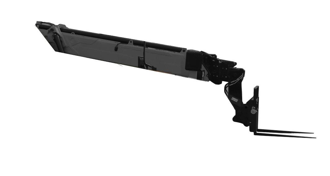
In order better to understand chain boom operation and dismantling procedure: 50 “ Boom schematic diagrams ”
The “Chain boom component dismantling” operation is done in several stages:
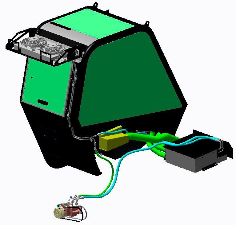
“ Hydraulic kit ”removal
“T2+T3 telescopes assembly ” removal.
The “Hydraulic kit removal” operation should be done
“ T3 Telescope ”removal.
The “Hydraulic kit removal” and “T2 + T3 Telescopes assembly removal” operations should be carried out
These various stages are detailed below in this chapter.
The table below shows the various actions to be taken on the chains to be replaced.
Chain descriptions
Extend T2
Extract T2 + T3 assembly. Retract T3

Retract T2
Extend T3
Action to be taken
Extract T1 + T2 + T3 + hydraulic kit assembly.
Note: It is not obligatory to remove the hydraulic kit to change the “ Retract T2 ” chain.
Extract T2 + T3 assembly, the extract T3.

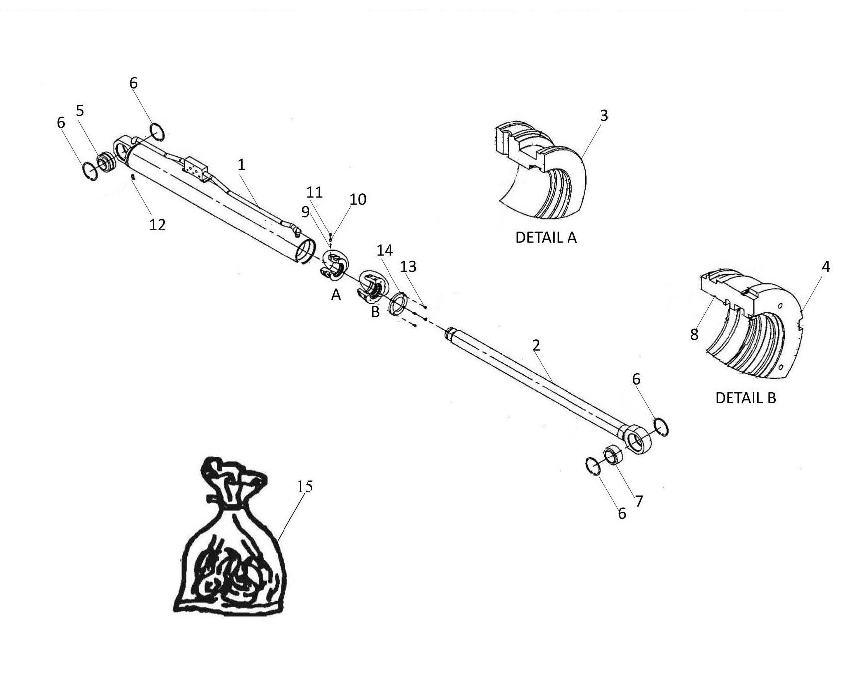
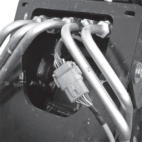
Disconnect the electrical connector (Item 8).
- Undo boom head stop (Item 12).
- Place an oil container under boom head.
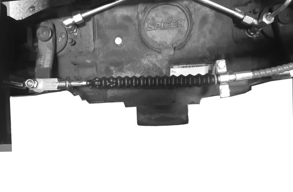
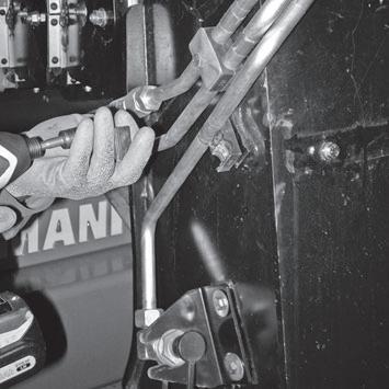
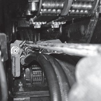
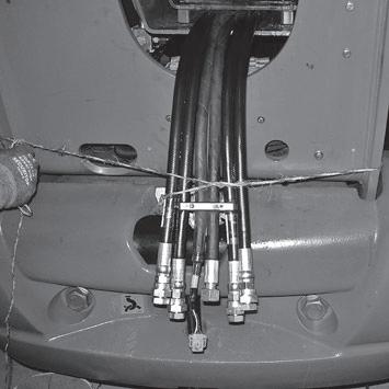
- Pull the set of five hydraulic tubes (Item 13) out from the boom head then use 27 mm wrench and 30 mm wrenches to undo them.
- Then use stoppers to plug the hydraulic connections to prevent any oil running out.
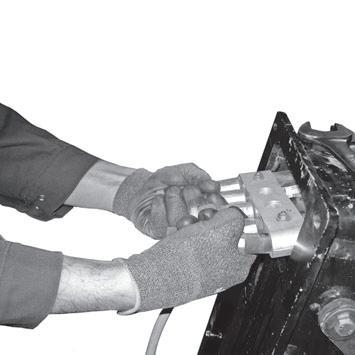
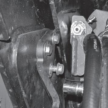
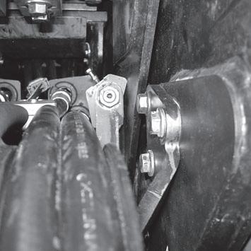
- Pull on the set of five hydraulic hosing pieces (Item 14) so as to extract the bracket (Item 15).


- Undo the two screws (Item 16) on the bracket.
- Remove bracket (Item 15).
Reposition


- Use the specific “ channel tool ” ( Item 25 ) to pull channel out ( Item 26 ) to release hosing pieces ( Item 27 ).
- First remove only the “pulley support” on the right side (Item 28).
Dislodge right hand pulley (Item 30) from its axle (Item 31).

- Do the same for the central pulley (Item 32).
- Then remove left hand pulley (Item 33) with its axle (Item 31).

- If possible use “ channel lever ” (Item 25 ) to push channel ( Item 26 ) to gain better accessibility for undoing the two “ spring support ” screws.
- Use 13 mm wrench to undo two right hand side “ spring support ” (Item 37 ) screws ( Item 36 ). - Carry out the same operation on the left hand side “ spring support ”.
- Use a tie ( Item 39 ) to attach electrical harness ( Item 38 ) so that it does not get damaged during hydraulic kit ( Item 40 ) extraction.
- Pull “ hydraulic kit ” assembly ( Item 40 ) out by some 50 cms o as to gain access for disconnecting five hosing pieces and disconnecting electrical connector.


Use 27 mm + 30 mm wrenches to disconnect five hosing pieces ( Item 41 ).
- Plug hosing piece ends with stoppers ( Item 42 ).
- Disconnect electrical connector (Item 43).
- Use a cord (Item 44) to tie hosing pieces against chassis to that they do not hamper hydraulic kit extraction.

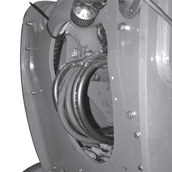
- Pull “hydraulic kit” assembly ( Item 45 ) out by about 1 meter.
Pull out also the hosing pieces ( Item 46 ) above it so as to ease extraction.
- Position sling and hoist ( Item 47 ) to keep assembly together during extraction.

- Pull out “ hydraulic kit ” assembly ( Item 45 ), checking that hosing pieces ( Item 46 ) follow the movement.
- Remove “ hydraulic kit ” assembly ( Item 45 ) and place on two trestles ( Item 48 ).