3 minute read
CHAIN TENSION PRE-SETTINGS DURING REASSEMBLY


STEP 1: “ T2 RETURN CHAINS ” PRE - SETTINGS
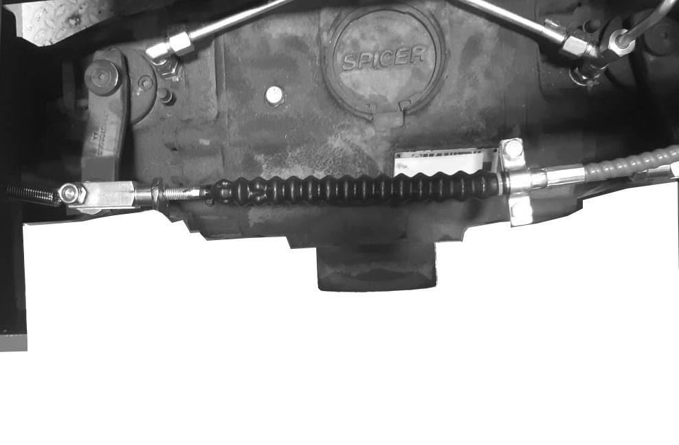
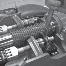
Adjust “ X1 ” dimension by turning nut ( Item 1 ).
With no worn chain replacement:
X1Left = Dimension read on “ left chain tensioner ” before dismantling.
X1Right = Dimension read on “right chain tensioner” before dismantling.
With worn chain replacement with new:
1. Measure the difference in length ( ∆ L ) between the chains.
2. Position the “left chain tensioner”at:
X1Left = 65 mm.
3. Position the “right chain tensioner”at:
X1Right = 65 mm - ∆ L ⇒ if LRight chain < LLeftchain
X1Right = 65 mm + ∆ L ⇒ if LRight chain > LLeftchain
STEP 2 : “T3 RETRACT CHAINS ” PRE - SETTING
Adjust “X2” dimension by turning nut (Item 2).
With no worn chain replacement : X2 = measured machine dimension before dismantling operation.
With worn chain replacement with new : X2 = 90 mm.
STEP 3 : “ T2 EXTEND CHAINS ” PRE - SETTING
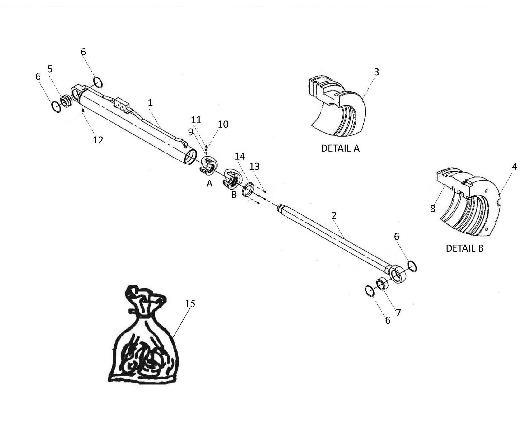
Before tightening nuts ( Item 3 ), protect the cylinder rod ( Item 8 ). Adjust “ X3 ” dimension by turning nut ( Item 3 ).
With no worn chain replacement : X3 = measured machine dimension before dismantling operation.
With worn chain replacement with new : X3 = 40 mm.
STEP 4 : “ T3 EXTEND CHAINS ” PRE - SETTING
Adjust “ X4 ” dimension by turning nut ( Item 4 ).
With no worn chain replacement : X4 = measured machine dimension before dismantling operation.
With worn chain replacement with new :
X4 = 55 mm.
- Carry out a full boom extend/retract cycle.
- With boom extended, “ extend chains ”should quickly be tensioned and there tract chains should take up a little slack.
- With boom retracted, “ extend chains ” should take a little slack and the retract chains should quickly be tensioned.
Checking And Setting Chain Tensions
The procedure is carried out with boom in horizontal position and in 2 situations:
⇒ During reassembly procedure of boom components or
⇒ During regular checks
1. Fully extend boom than retract it by a total of 200 mm.
2. Monitor “extend chains”slack:
⇒ H1 = 75 0 mm
⇒ H2 = 107 0 mm
Turn their nuts to obtain dimensions “ H1 ” and “ H2 ”.
The left and right chains must have the same dimension or within 2 mm.
3. Fully and carefully retract the telescopes.
4. Check that the telescopes are at the mechanical stop. If they are not, measure the following clearances :

⇒ Clearance between T1 and T2 ( Item 6 )
⇒ Clearance between T2 and T3 ( Item 7 )
Acceptable clearance = less than 3 mm
Loosen T2 chain exit by clearance value T1/T2
Tighten T2 chain retraction by clearance value T1/T2 Loosen T2 chain exit by clearance value T1/T2
Tighten T2 chain retraction by clearance value T1/T2 Carefully retract the boom
Fully extend boom than retract it by approx. 200 mm.
Fully extend boom than retract it by approx. 200 mm.
Tighten T2 exit chains: dimension 107₋⁰₁₀ mm above T1
Tighten T2 exit chains: dimension 107 0 -10 mm above T1
Tighten T3 exit chains: dimension 75₋⁰10 mm above T2
Tighten T3 exit chains: dimension 75 0 -10 mm above T2
Carefully extend and retract boom
Note : Where there is a difference in tensioner length on a pair of chains, keep the difference, do not adjust the tensioners to the same dimensions.
5. Tighten up lock nuts for each “ chain tensioner ”once all chain tensioner settings have been done. Apply tightening torque to lock nuts:
C = 85 N.m
6. Refit split pins to each “chain tensioner”.
The “ T3 Telescope refit” operation should be done.
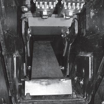
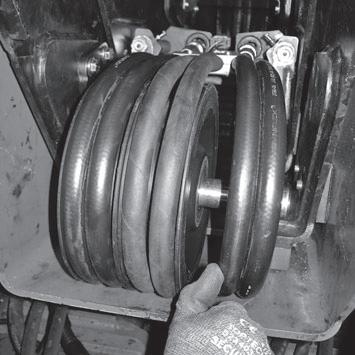
- Put special “ hosing path support ” tool ( Item 1 ) inside T3 telescope. This tool helps insert hosing pieces into the hosing channel.
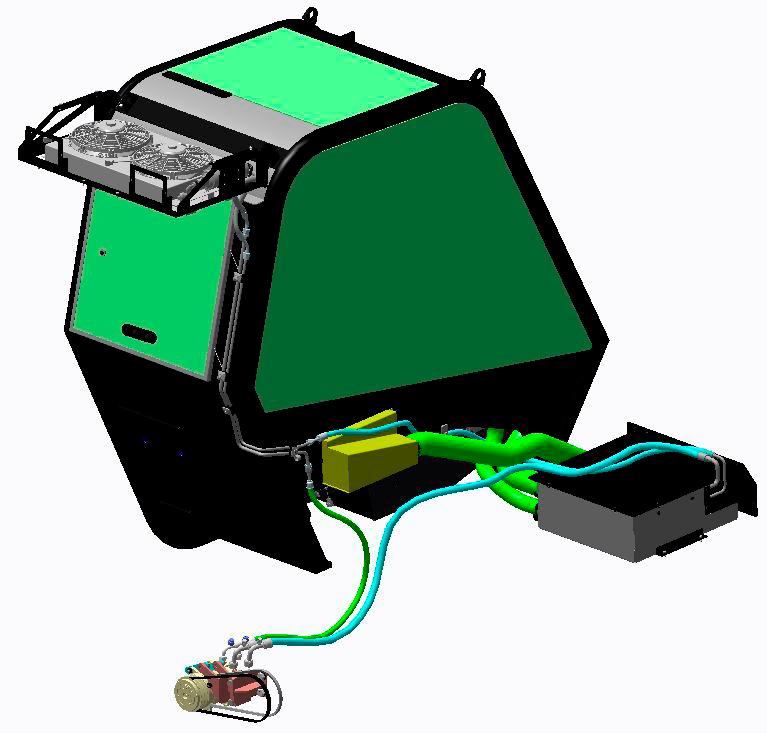
- Use sling + hoist to position “Hydraulic kit” at rear of truck.
- Apply a layer of grease to channel in pad support areas between channel and T3 fixed pads.
- Lay hosing + electrical harness ( Item 2 ) into channel by sliding them in using special tool ( Item 1 ).

Take out special tool ( Item 1 ).
- Insert“ Hydraulic kit ” by inclining it so that it passes over the “T3 retract chain”.
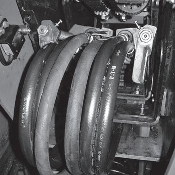
- Connect up hosing pieces and electrical connector ( Item3 )at boom foot. Place an oil container to recover any oil coming out of hosing pieces.

- Fully insert “Hydraulic kit” into boom.
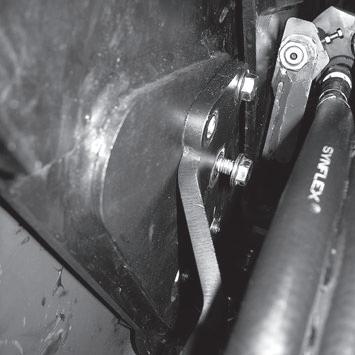
Fix “ spring support bracket ” ( Item 4 ) to T2 telescope ( Item 5 ). To do that, do up two screws ( Item 6 ) on each side of T2 telescope. Apply “ Loctite 243 normal thread lock ” to fasteners.
“Spring support” should be fixed in an upper position in the orifices as shown in the photo.
Fix “ left pulley support bracket ” ( Item 7 ) on T1 telescope ( Item 8 ). Spread “ Loctite 243 normal thread lock ” on three screws ( Item 9 ) then screw them in.